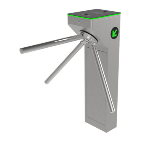
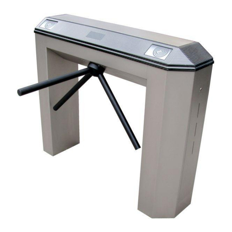
polimek BT 312 S Manual

• ®
OIME<
-,
/ -�,
\
'
www.polimek.com. tr

DD-75-181 R(2) Y.T.13.07.17
2

DD-75-181 R(2) Y.T.13.07.17
3
1. GENERAL INFORMATION …………………………………………………………………..………….…. 4
1.1. Preface
1.2. General Information on Turnstiles
1.3. Full-Height Turnstile Models
2. SAFETY AND OPERATION…………………………..……………………………….…...........................5
2.1. Safety Warnings And Symbols
2.2. Fuse Replacement
2.3. Safety Related Instructions
2.4. Operating Conditions
3. HANDLING AND INSTALLATION ..........................……………………………………......................….6
3.1. Handling
3.2. Installation
3.3. Mounting of Arms
4. TURNSTILE SYSTEM SPECIFICATIONS………....…………………………............….........................7
4.1. FullHeightTurnstileTableofSpecications
4.2. FullHeightTurnstileSystemSpecications(Standard)
4.3. FullHeightMotorizedTurnstileSystemSpecications
4.4. Indicators
4.5. Accessories
5. SETUP AND OPERATION……………………….................………..........……..……………..…………..9
5.1. Power and Ground Connections
5.2. Control Board Connections
5.3. Wiring Diagrams
5.3.1. Control Board Terminals
5.3.2. Internal Wiring Diagram
5.4. Control Board Settings
5.4.1. Inhibit(Enable/Disable)Terminal
5.4.2. Dip Switch Settings
5.5. HydraulicDamperAdjustment(ManualModels)
6. POST INSTALLATION CHECK LIST………………………………………............…………………......15
7. SERVICE AND MAINTENANCE…………………………………..........................................................15
7.1. Maintenance Instructions
7.1.1. Recommended User Maintenance
7.1.2. Periodic Maintenance by Technical Service Personnel
7.2. Trouble Shooting And Repair Guide
7.3. MechanismAssemblyExplodedDiagrams
8. LIST OF COMMON REPLACEMENT PARTS…………..................................…........……………….19
9. CE DECLARATION OF CONFORMITY AND WARRANTY….........……………………….................20
9.1. CEDeclarationofConformity
9.2. WarrantyCerticate
9.3. Warranty Terms and Conditions
9.4. CasesExcludedfromWarrantyCoverage

ıe 12 o
4

DD-75-181 R(2) Y.T.13.07.17
5
2. SAFETY AND OPERATION
2.1 Safety Warnings and Symbols
ForSafetyandproperoperationoftheturnstileallinstallationandrepairworkmustbeperformedbyqualied
technical personnel only!
WARNING!
Never remove the protective cover of the power
supply unit for any reason!
Observe the warning signs, power and fuse
values when performing any work on the turnstile.
Warning labels and power supplies may vary
depending on the turnstile model and type.
WARNING! To avoid shock hazard AC power connections
must be properly grounded!
TURNE ENER ETET
WARNING/DİKKAT
220 v. 50Hz.
FUSE 3A
ERT
N
F
FUSE
GROUNDING SYMBOL
2.2. FUSE REPLACEMENT CAUTION! Use only the same type and rating of
fuse as selected by the manufacturer!
Gn d .
F.P
N
The fuse and a spare are located inside AC power socket
POWER CONNECTOR FRONT VIEW
HIGH VOLTAGE WARNING LABEL
Spare Fuse

DD-75-181 R(2) Y.T.13.07.17
6
2.3 Safety Related Instructions
1. Users must not dismantle the turnstiles. Maintenance can only be performed by competent and authorized
personel.Maintenanceworkattemptedbynon-qualiedindividualsmaycreatedangertousersandtheturnstile.
2. Turnstilemustnotbeinstalledatplaceswherethereisariskofexplosioncausedbyelectricalarcsoraprobable
gas leakage.
3. Turnstilemustbekeptawayfromammableenvironments.
4. Turnstile should not be installed at places where there is vibration.
5. Turnstilemustnotbekeptinexcessivelymoistenvironments.
6. Turnstilemustnotbeexposedtoheat.
7. Turnstilesmustnotbesubjectedtoabusivetreatmentsuchasimpactorexcessiveshaking.
8. Turnstilemustbekeptawayfromhighlevelmagneticelds.
9. Operatingvoltage/powerrangemustbeobservedinallinstallations..
10. The power must be stable, properly grounded, insulated.
11. Turnstilescanonlybeoperatedundertheenvironmentalconditionsandtemperaturesspeciedbythemanufacturer.
12. Children must not be allowed to play with the turnstiles.
13. Allconnectionsmustbeconrmedtobecorrectbeforesupplyingpowertotheturnstile.
14. Only materials and equipment recommended by the manufacturer must be used for the turnstile when making
connections into the input and output terminals.
15. All parts and accessories used in the turnstiles must be approved by the manufacturer.
16. In case of any electrical arching or faults caused by such condition, power must be disconnected and authorized
servicer or manufacturer must be contacted as soon as possible.
17. The power must be cut off before cleaning or maintenance.
18. Onlyclean,softandmoistfabrics(noabrasivematerialsorchemicals)shouldbeusedforcleaningtheturnstile.
19. Damaged turnstiles must not be operated, and the authorized dealer or the Manufacturers technical support
center should be contacted soon as possible for repair.
2.4 Operating Conditions
1. More than one person must not attempt to pass at the same time.
2. Turnstile must not be forced, kicked, abused or tempered with to gain passage without authorization.
3. Turnstilesmustnotbewashedforcleaningpurposes(applyingwaterwithahoseorpouringwaterfromabucketetc.).
Wipingoffwithnon-abrasivematerialssuchasasoftandcleandampclothissufcientinmostcases.
4. Chemicals and abrasives must not be used in any case for cleaning. The manufacturer is not responsible for damages
resulting from use of such materials.
3. HANDLING AND INSTALLATION
3.1 Handling
1. Please pay special attention to carry the turnstiles as originally packed by the manufacturer.
2. Follow the handling and carrying instructions written on the package.
3. Do not place a heavy load on the turnstile package.
4. Do not place the packed turnstile on a wet ground.
5. Do not leave the packed turnstile under rain.
6. Duringhandling,useanappropriatelift/cranewith
sufcientliftingcapacity.
7. Before starting installation ensure that there is no
shipping damage or missing parts and hardware inside
the package.
3.2 Installation
1. The installation place should be selected
according to user’s requirements. This selection
should not prevent the smooth operation of the
turnstiles.
2. Ensurethattheinstallationsurfaceisat,evenandofproper
strength.Flattenanyuneven/roughareasifnecessary.
3. Mark the holes and drill with a 12 mm drill bit. Clean the
debris inside the holes by pressurized air.
4. Filltheholeswithchemicalplasterandxanchoringbolts
(10mm)inplacebyrotating.Chemicalplasterdriesinabout25
minutes.
5. Place turnstile on anchoring bolts and tighten the nuts to
secure in place.
6. Connect power and control cables. Power and control cables
can be routed up through the structural pipes of the turnstile
usingguidewires.Cablelengthextendingfromgroundshould
be at least 4 meters.
Note: A model specic mounting plan is supplied with each
turnstile.
MOUNTINGDETAILS
GROUNDPLAN
M10NUT(CLOSEDTOP)
M10 NUT
M10LOCKWASHER
M10WASHER
M10x200STUDBOLT
TURNSTILEBODY
Chemical Anchor
GROUND
110 mm 60mm 30
200 mm

DD-75-181 R(2) Y.T.13.07.17
7
3.3 Mounting of Arms
Caution! Arms can loosen and fall
if not mounted correctly.
Kilitlemepimleri
Attach arms on the rotor and turn counter
clockwise until lock pins are engaged to
prevent removal of the arms by turning.
Fullytightenarmbolts(applyloctide)and
install arm caps by tapping with a rubber
hammer.
Liftthemechanismchannelatoneendto
correctly adjust rotor position and re-seat
it on the rotor coupler. Refer to detailed
assemblyinstructionssupplıedwitheach
turmstile model.
19 mm socket wrench
with long handle
Mounting of Arms
Incorrectly Installed Rotor Correctly Installed Rotor
4. TURNSTILE SYSTEM SPECIFICATIONS
4.1 Full Height Turnstile Table of Specications
Lockpins
Manual Motor
Driven Movement Lock Control Stop Structural Materials
Rotor
&
Arm
Arm
Configuration
BT 312 S / D
3 Arms (120˚)
BT 402 S / D
4 Arms (90˚)
BTE 312 S /D
3 Arms (120˚)
BTE 402 S / D
4 Arms (90˚)
BTX 100 1 Arm (90˚+90˚)
BTX 300 S / D
3 Arms (120˚)
BTX 400 S / D
4 Arms (90˚)
BTA 300 *
3 Arms (120˚)
ECOLINE 300 S / D
3 Arms (120˚)
ECOLINE 400 S / D
4 Arms (90˚)
BT 302 GL *
3 Arms (120˚)
BT 400 GL *
4 Arms (90˚)
BT 402 GL *
4 Arms (90˚)
MODEL
-Glass (Side Walls)
-Aluminium
-304 / 316 Grade Stainless Steel
Mechanism
Operation
Materials
Hydraulic Damper
-Hot Dip Galvanized Steel
-Hot Dip Galvanized and
Electrostatic Powder Coated
Steel
-304 / 316 Grade Stainless
Steel
-Acrylic (arm,for BTA300)
Ο
Push to
Rotate
(Optional
Motorized)
Solenoid
Hot Dip Galvanized Steel
-Hot Dip Galvanized and
Electrostatic Powder Coated Steel
-304 / 316 Grade Stainless Steel
: Standard
Ο:Optional
* : Opt. different materials

DD-75-181 R(2) Y.T.13.07.17
8
4.2 Full- Height Turnstile System Specications (Standard)
1. System is designed for bi-directional operation. In standard models, when power is cut off, arms freewheel to allow
freepassageinbothdirections;optionallythesystemcanbesetuptolock(fail-lock)whenpoweriscutoff.
2. Mechanical parts of the turnstiles are made of stainless steel and galvanized metal. All locking mechanism
components are made of stainless steel.
3. Once passage is permitted and arms rotate 30 degrees, arms will not return, and another passage is not allowed by
the system until the completion of the movement.
4. After each complete passage the manual system returns to standby position smoothly and quietly by means of a
hydraulic shock absorber. Motor driven versions complete rotation by a light push following authorization.
5. Signalizationisprovidedwithdirectionindicatorsplacedonbothsidesoftheupperbodyoftheturnstile(While
greenarrowindicatesactivepassagedirection,redbarshowstheinhibitedpassagedirection).Inadditiontothevisual
signalizationwithgreen/redindicators,anaudiobuzzersignalisprovidedduringpassage.
6. SolenoidsusedwithinthesystemaredrivenbyPWMforreliability,optimalenergyefciencyandlessheat.Theydo
not warm up to more than 10 degrees above the ambient temperature.
7. Electronicboardcontrollingthesystemis“coatedinsidethehole’type”andthereforenotaffectedbyvibration.
8. The micro-processor based electronic control system used in the turnstiles can be programmed for various
functions and operating modes by a simple dip switch selection.
9. All inputs and outputs are isolated by opto-coupler and relay components for increased reliability.
10. Turnstilepassagedirectionscanbeinhibited(closed),setupforonewaytrafcornormalbi-directionaloperation
byenable/disableterminallocatedonthecontrolboard.
11. Thepowersupplyissupportedby“switching-mode”technologyforbettervoltageregulationandenergyefciency.
12. Turnstile only allows passages of authorized people. If a person does not pass within a pre-set time limit following
authorizationcontact(selectablefor6,12,18orinniteseconds),thesystemautomaticallylocksandreturnsto
standby.
13. After each complete passage, the system provides dry contact relay output for each direction. An optional counter
can be used.
14. Electroniccontrolunitoftheturnstileisprotectedagainstwaterforoutdoorinstallations.
15. Turnstiles can work in sync with door-type metal detectors; In security applications, even passage of a person with
authorization can be blocked automatically upon receiving contact from a metal detector. The system can be returned
to normal operation by the operator.
16. Incasesofemergencytheturnstilecanbeswitchedinto“emergencymode”withanormallyclosedmanualbutton
orrelayfromrealarmsystem.Inemergencymodearmsrotatefreelyinbothdirectionsallowingfreepassage.
17. Turnstilepassagedirectionscanbearrangedindifferentcombinationsbyadipswitchonthecontrolboard.(For
example:onedirectioncontrolledotherdirectionfree;bothdirectionscontrolledbyseparatereaders,singlereaderfor
bothdirections.)
18. Turnstiles allow passage of only one person at a time for each authorization contact into the control board.
19. Card readers or similar access control systems can be integrated into the turnstiles separately or jointly for
controllingbothsidesdependingontheneedsandspecicrequirements.
20. Onceapassageiscompleted,anentranceorexitdirectiondata(drycontact)isprovidedtothedatacollection
terminal.
4.3 Full Height Motorized Turnstile System Specications
1. Microprocessorcontrolledbi-directionalsytemincorporatesanefcientPWMdrivenDCmotor.
2. Upon passage authorization received by the control board, system activates the motor following a light push on
the rotor and completes the rotation of 90° or 120° depending on the model. The rotor stops and tries to continue its
rotation once more if it meets an obstacle during its movement. If the obstacle is still present the rotor stops an alarm
is activated.
4. Followingacompletepassage(90°or120°rotation)turnstilelocksandbecomesreadyforthenextpassage.
5. Emergency mode: Controlled by a normally closed (NC)buttonorrealarmsystemcontact.Turnstilewillrotate
free in both directions as long as the emg contact remains open. Upon re-establishment of emg contact, turnstile
returns to normal operation mode.
REDX:Passagewayclosed(see5.2’) GREENARROW:Passagewayopen.
Buzzer is heard when a passage is authorized.
In alarm mode the indicators alternately blink in red and green and buzzer is heard.
4.4 Indicators
The system features status indicators on both sides and a buzzer for user guidance.

DD-75-181 R(2) Y.T.13.07.17
9
4.5 Accessories
RemoteControl(Wired)
Reader Post Mounting Bracket Mounting Bracket Reader Bracket With Pole
CounterRemoteControl(RF)
5. SETUP AND OPERATION
5.1. Power and Grounding Connections
TURNE ENER ETET
WARNING/DİKKAT
220 v. 50Hz.
FUSE 3A
ERT
N
F
FUSE
Warning! Power and grounding connections must be made by a qualied electrician in accordance
with the relevant local regulations using appropriate materials!
Proper grounding must be ensured to prevent shock hazard!
Gn d .
F.P
N
Warning! Do not attempt to repair the
power supply by removing the cover. Power
supply must be replaced in case of failure
with an original unit which can be obtained
from Ozak.
TURNSTILE POWER WARNING LABEL
Coin System

5.2 Control Board Connections
2.
Caution!
Caution!
3.
INA }
Note:
DD-75-181 R(2) Y.T.13.07.17

DD-75-181 R(2) Y.T.13.07.17
11
SN
Access Control Terminal
Res
+24V
B-AB-A or A-B
A-B
N.O.
N.O.
Com
Com
Gnd
Gnd
Emg
INB
Gnd
Gnd
Gnd
Gnd
INA
1
23 7
56
8
- Power +
B-AA-B
J3
Top IndicatorsSide Indicators
Solenoid Out
Solenoid Out
Direction Sensors
ON
DipSwitch
1234
U2
U7
U1
RL1
RL2
U9
Prg: XXXXXXXXXXX
Rx
Tx
I/O_1
I/O_2
I/O_3
I/O_4
Out_P3
Out_P2
Out_P1
+5 V
+24 V
Gnd
0.5 - 1 sn dry contact
or open collector input
888888
Optional counter
1N4001
or similar
Busy Out
or or
TRN1202
0.5 - 1 sn
busy
B-AA-B
Enable
Gnd
Passage conrmation dry contact output
Use with access control systems, counters etc.
accessories (0.5 sec. N.O. contact)
Buzzer Jumper
(Buzzer disabled when removed.)
Connec
t a jumper from Enable A-B or B-A to Gnd to block
a passage direc
tion.
Res: Manual Time Reset (Optional)
24 VDC
Optional counter
sample connection
During Passege = 0
Emg: Emergency-Free Access Mode
(when contact is open.)
Gnd
Enable
5.3 Wiring Diagrams
5.3.1 Control Board Terminals
*Motor Control
(Motorized Model)
*

DD-75-181 R(2) Y.T.13.07.17
12
1. Solenoid A-B
2. Top Passage Indicator and Buzzer
3. Side indicators
4. Optional Comm. Port
5. Solenoid B-A
6. Direction Photo Sensor
7. Motor Control
8. Power Input (24 VDC)
9. Dip Switch
10. Control Inputs
11. Passage Confirmation Contact
12. Buzzer Enable/Disable
13. External Module Connector
(Motor Driver, Drop Arm Control etc.)
14. Enable Disable (inhibit)
A. Board Serial Number
B. Stock Code
C. Production Number
D. Board Model
--------------------------------------------------------------
SN
Res
+24V
B-A
A-B
N.O.
N.O.
Com
Com
Gnd
Gnd
Emg
INB
Gnd
Gnd
INA
1
23 7
56
8
- Power +
J3
Top IndicatorsSide Indicators
Selenoid Out
Selenoid Out
Direction Sensors
ON
DipSwitch
1234
U2
U7
U1
RL1
RL2
U9
Prg: XXXXXXXXXXX
10
11
2
3
1
6
57
13
A
A
8
D
D
C
C
B
B
9
12
Motor Control
B-AA-B
Enable
Gnd
14
5.3.2 Internal Wiring Diagram

DD-75-181 R(2) Y.T.13.07.17
13
5.4 Control Board Settings
5.4.1 Inhibit (Enable/Disable) Terminal: To inhibit access through the turnstile in A or B direction, short A-B or B-A
terminal to Gnd with a jumper. Turnstile will not allow passage in the inhibited direction and indicator for that direction
will turn red to show inhibited access. This feature can be used with a metal detector to automatically block Access for
Security purposes or setting the turnstile for one way passage.
5.4.2 Dip Switch Settings
Timeoutandmodesettingsoftheturnstileareselectedbythedipswitchlocatedonthecontrolboardasexplained
below.
1. Bi-directional controlled passage: A seperate card reader or button is used for each direction
2. Bi- directional passage by a single control device: A single reader or button connected into In A allows
passage in both directions
3. Adirectionfree,Bdirectioncontrolledpassage:Example:Controlledentry–freeexitintoabuilding.
4. B direction free, A direction controlled passage
1 2 3 4
ConnectajumperfromEnableA-BorB-A
to Gnd to block a passage direction.
ON
OFF

DD-75-181 R(2) Y.T.13.07.17
14
Damper Adjustment:
Due to large variations in ambient
temperature or wear hydraulic
damper adjustment may be required.
Example;Inverycoldtemperatures
damping should to be reduced if the
rotor can not quickly return to rest
position following rotation. In warm
areas, if the rotor fails to stop
smoothly at the rest position and
bounces, then the damping should be
increased.
Before adjusting the damper, loosen
the dial stop screw with 1.2 mm. Allen
key taped on the mechanism.
5.5 Hydraulic Damper Adjustment (Manual Models)
Note: Damping factor is
increased when dial is turned
clockwise.
Once the adjustment is done, tighten
the stop screw while holding the dial
steady with the other hand.
Caution! Dial is very sensitive. It
must be adjusted carefully in small
increments.
Caution! To prevent damage due
to bottoming out of the damper
during operation, ensure that there
isapproximately3mm.clearance
between the damper head and the
body when the damper arm is fully
pushed in. Use loctide on damper
mounting nuts to prevent loosening
by vibration when clearance
adjustment is performed.
1.2mm.Allen
Key
Hydraulic
Damper
1.2 mm. Allen
Key
Hydraulic
Damper

DD-75-181 R(2) Y.T.13.07.17
15
1
No Item to Check Remarks
2
3
4
5
6
7
8
9
10
11
12
13
14
15
Adjust damper if rotor is bouncing or too stiff.
Standardfail-safeconguration.Fail-locked
option is available.
Unit is properly grounded.
7. SERVICE AND MAINTENANCE
7.1 Maintenance Instructions
7.1.1 Recommended User Maintenance
• Periodicallywipetheturnstileexteriorwithaclean,dampandsoftclothtokeepitfreeofdust.
• Inspectexternalmountingscrews,panels,armsetc.onceeverythreemonthsorasrequiredtoensurethatthereare
no loose, worn out or damaged items. If there are loose or damaged items contact your authorized dealer or Ozak.
• Checkthattheturnstileisrmlyanchoredonthesurface.(Nolooseordamagedanchoring).
• Check that all mechanical movement is smooth and quiet with no unusual noise, rattling etc.
• Inspect electrical cables and connections for any damage, water contamination, loose connections or wear. Contact
your authorized dealer or the manufacturer if any problem is detected.
• Ozakusesonlythenestqualitycerticatedsteelobtainedfromreputablesuppliersformaximumcorrosion
resistanceandstrength.Duringourmanufacturingprocesswetakealltherequiredstepstoensurethatthenished
productshaveexcellentcorrosionresistance.Dependingontheenvironmentalconditions,theremaybestainingissues
on some turnstile surfaces in outdoor installations if regular cleaning and maintenance is not performed. On 304 and
higher grade steel surfaces, these stains are not actual rust, but only accumulation of airborne particles sticking on the
surfaces. These type of stains can be cleaned off and prevented by periodic maintenance recommended below.
• Cleaning the turnstile surfaces by wiping with a clean, dust and grit free absorbent cloth is effective in most cases.
Harsh abrasives should never be used on polished metal surfaces. Commercially available appropriate metal polishing
compounds can be used for removal of tougher stains. The recommended frequency of cleaning depends on the local
environmentasexplainedintablebelow.
Do not wash the turnstile with pressurized water.
There are no user serviceable items inside the turnstile. Do not attempt to do repair work such as lubrication, part
replacementoradjustmentsinsidetheunit.Allsuchworkmustbeperformedbyqualiedtechnicalpersonnelonly!
6. POST INSTALLATION CHECKLIST
Environment Type 304 Type 316
Seafront Frequently as required Monthly
Coastal(Within5kmofthecoast) Frequentlyasrequired 6-12months
Industrialandurban 3-6months 6-12months
SuburbanRural Annuallyorasrequiredbyexperience
Internal As required to maintain appearance
Installationsurfaceisat,evenandsufcientlystrong
All wiring is routed and connected properly
All AC power lines are properly insulated and grounded
Turnstileispositionedandmountedcorrectlyandrmly
All anchoring bolts are secured in place with chemical plaster.
Allanchoringhardwaretightenedproperly(noloosenuts/boltsetc,
turnstileisrmlymountedonthesurface).
All arms, covers, panels, readers etc. are mounted correctly
Nophysicaldamageorirregularities(dents,scratches,brokenitemsetc.)
When powered up all indicators are normal, solenoids locked, buzzer
initialbeepisheard,rotor/panelinstandbyposition)
Turnstile allows passage in A direction when contact is given on Input
A and Gnd. Opposite side indicator turns red until rotation complete.
Turnstile allows passage in B direction when contact is given on Input
B and Gnd. Opposite side indicator turns red until rotation complete.
Turnstilerotor(orpanel)operatesquietly,smoothlyandreturnsto
center(standby)positionwithoutbouncing.
InEmg(emergency)modeturnstileallowsfreepassageinboth
directions while buzzer is heard.
When power is cut off, turnstile allows free passage in both directions
by pushing
AC potential between turnstile ground and neutral is less than 0.5V.
Goodcontinuity(0Ohm)betweenchassisandground.

DD-75-181 R(2) Y.T.13.07.17
16
Check/tightenifrequired
Check
Check/tightenifrequired
Check + Grease
Check
Check+Lubricate
Check
Check(freemovement)
Check
Check(freemovement)
Check + Adjust
Check/replaceifrequired
Check
Check
Check
Check
Check
Check + Clean Dust
Check + Clean Dust
Check
Check +Clean Dust
Check
Anchoring nuts and bolts
Topcover/Lock/Sealsanddrainage
Rotorarms/bolts
Rotor bottom bearing
Rotor coupling and connections
Main rotor shaft
Clampspring,damperarmbearing(manualtype)
Lockleversandsprings
Solenoids
Ratchet mechanism and spring
HydraulicDamper(Manualtype)
Hydraulic damper arm bearing
Motor(Motordriventype)
Motorpulleyanddrivebelt(Motordriventype)
Mechanism mounting nuts and bolts
Mechanism Bearings
Power connections, wiring and grounding
ElectronicControlBoard
Positioning photosensor
Wiring and connectors
MotorDriverBoard(Motordriventype)
Indicators and buzzer
12 Month
12 Month
12 Month
12 Month
12 Month
12 Month
12 Month
12 Month
12 Month
12 Month
12 Month
12 Month
12 Month
12 Month
12 Month
12 Month
12 Month
12 Month
12 Month
12 Month
12 Month
12 Month
General
Mechanism Assembly
ElectricalComponents
Full Height Turnstiles Maintenance Item Period Recommended Action
7.2 Trouble Shooting and Repair Guide
7.1.2 Periodic Maintenance by Technical Service Personnel
Description of Fault Possible Cause Recommended Action
Nopower.(indicators,buzzer,
locksoff)
Rotor free wheels when power
is on
Note:EnsureEmg.terminalis
not activated and dip switches
3 and 4 are off
Turnstile does not allow
passage when input contact is
given-buzzer heard
Rotor/armsdonotreturnto
center(standby)position
following a passage
Rotor bounces back and forth
following a rotation, fails to
settle in rest position smoothly
1. No AC power supplied to unit.
2. Loosepowercable
3. Blown fuse
4. Faulty power supply unit
1. Loosesolenoidorphotosensor
connector
2. Faulty photo sensor
3. Faulty solenoid
4. Faulty control board
Note: periodic beep and red indicators
indicate a loose or faulty photo sensor.
1. Restricted lock lever movement
(duetoforeignobjectsuchascable,
gummedlubricantetc.)
2. Sticky solenoid
3. Faulty control board
4. Misaligned/bentphotosensorin
motorized units
1. Looseorbrokenclampspring
2. Over damped hydraulic damper
setting
1. Under damped hydraulic damper
setting
2. Wornout/faultyhydraulicdamper
1. Restore AC power.
2. Connect power cable.
3. Replacefuse(see2.2)
4. Replace power supply unit
1. Re-insert connector
2. Replace photo sensor
3. Replace solenoid.
4. Replace control board
1. Repair lever mechanism
2. Replace solenoid
3. Replace control board
4. Adjustphotosensor(motorized
units)
1. Re-install/replaceclampspring
2. Adjusthydraulicdamper(see5.5)
1. Adjusthydraulicdamper(see5.5)
2. Replace and adjust hydraulic
damper

DD-75-181 R(2) Y.T.13.07.17
17
Arıza Tanımı Olası Nedeni Önerilen Çözüm
Turnstilefailstolock/free
wheels following passage
Rotor gets stuck
intermittently during rotation
Noresponsetoinput/reader
device. No access
Nopassageconrmation
contact out of control board
Turnstile free wheels in one
direction
Turnstile unlocks upon input
but motor does not run
(motorizedmodels)
Motorized rotor keeps
moving/failstostopin
middle position.
Motorized rotor turns too
slowandtimesout/alarm
activated.
1. Dislocated, broken lock lever spring
2. Solenoid failure
3. Looseorfaultyphotosensor
1. Looseorbrokenratchetspring
1. Loose/incorrectreaderconnection
2. Reader fault
3. Faulty control board
1. Looseconnectionatoutputterminal
2. Faulty control board
1. Dip switch 3, 4 might be set for free
passage(see5.4.2)
2. Loosesolenoidconnector
3. Looselockleverspring
4. Jammed lock lever
1. Loosemotor/motordriverboard
connection
2. Tripped motor driver protection circuit
breaker or blown fuse
3. Faulty motor driver board
4. Faulty motor
1. Loosephotosensorconnector
2. Misaligned, bent or contaminated photo
sensor
3. Faulty photo sensor
1. Too low motor speed setting on motor
driver board
2. Looseoroilcontaminateddrivebelt
slipping
1. Repair/replacelockleverspring
2. Replace solenoid.
3. Re-connect, replace photo sensor
1. Re-install/replacespring
1. Check/repairreaderconnections
2. Replacefaultyreader/inputdevice
3. Replace control board
1. Repair connection
2. Replace control board
1. Set dip switches ‘off’
2. Re-insert connector
3. Repair lock lever spring
4. Repair lock lever
1. Repair/tightenconnection
2. Doapoweroffreset/replaceblown
fuse
3. Replace motor driver board
4. Replace motor
1. Repair/tightenphotosensorconnector
2. Adjust/cleanphotosensor
3. Replace photo sensor
1. Increasemotorspeed(turnspeed
controlinccwdirection)onmotordriver
board
2. Clean/tightendrivebelt
Lockleveractionmustbefreeandsmooth.
Clean and apply light machine oil if lock
lever is jamming.
Photo sensors must be symmetrically aligned with
the disc slot at stop position and never in contact
with moving parts. Keep free of dust, grease etc.
LOCK LEVER MOVEMENT PHOTOSENSOR ALIGNMENT
Description of Fault Possible Cause Recommended Action

DD-75-181 R(2) Y.T.13.07.17
18
7.3 Mechanism Assembly Exploded Diagrams

DD-75-181 R(2) Y.T.13.07.17
19
ArmCap(StainlessSteel)
ArmCap(Plastic)
Bearing Ball
ClampSpring(3-WingModels)
ClampSpring(4-WingModels)
Couplin
Direction Photosensor
DownLight(Led)
Hydraulic Damper
HydraulicDamperBearing(608)
Indicator(Partnumbervariesdependingonserialnumber)
LockLever
LockLever
MainControlBoard(1202SM)
Microprocessor(Firmwarecodemustbespeciedwithorder)
Motor(24VDC/60W)
Motor Belt
MotorDriverBoardı(MC24SM)
SMPS(50W/24V)
SMPS(100W/24V)
Solenoid(5V)
20 02 02 0323
20 02 03 0027
10 00 10 0023
20 02 07 0013
20 02 07 0029
20 03 01 0399
3001140006
10 09 02 0001
10 02 00 0001
10 00 10 0001
----
20 02 00 0041
20 02 00 0098
30 01 01 0020
10 01 23 0001
10 01 34 0001
10 04 19 0004
30 01 03 0012
10 01 35 0017
10 01 35 0013
30 01 10 0005
5
6
7
8
9
10
11
12
Ref. Description Part Code Standard Motorized
1
6
11
16
2
7
12
17
3
8
13
18
4
9
14
19
5
10
15
Note:Pleaseprovideserialnumberoftheturnstilewhenorderingreplacementparts.Partspecicationscanvary
depending on the manufacturing date and optional features.
8. LIST OF COMMON REPLACEMENT PARTS
1
2
3
4
Use only original OZAK replacement parts!
13
14
15
16
17
18
19

CE UYGUNLUK DEKLARASYONU / CE DECLARATION OF CONFORMITY
• ® CE
OIME(
DD-75-181 R(2)
MANAG
Y.T.13.07.17
This manual suits for next models
20
Table of contents
Other polimek Turnstile manuals
Popular Turnstile manuals by other brands

Detex
Detex DSI DS500 Service & installation manual

BOON EDAM
BOON EDAM Tourlock 120/22 Safety and User Instructions

Dahua
Dahua DHI-ASG2900C user manual

digicon
digicon dflow product manual

Gunnebo
Gunnebo DL645 Operation and maintenance manual

Alvarado
Alvarado SW1000 Assembly, installation and operation instructions

Controlled Access
Controlled Access HS400 Series Service & installation manual

ZKTeco
ZKTeco Mars Pro-S1000 user manual

ZKTeco
ZKTeco TS2000 Series user manual

Tiso
Tiso ASTM F2656 M40 Installation and operation manual

digicon
digicon catrax master product manual

Tiso
Tiso ASTM F2656 M50 Installation and operation manual