metraTec TUC User manual
User Guide
for metraTec TCP/IP to UART Converter (TUC)
Date: March 2 17
Document-Version: 1.6
For Firmware 1.1 and higher
User Guide metraTec TUC Page 1 of 3

Table of Contents
1 General Information......................................................................................................................4
1.1 Symbols Used........................................................................................................................4
1.2 Further Documentation..........................................................................................................4
2 Configuration via Web-Interface...................................................................................................5
2.1 Login...................................................................................................................................... 5
2.2 Network Settings...................................................................................................................6
2.3 Port Settings..........................................................................................................................6
2.4 Misc. Settings........................................................................................................................7
2.5 Applying Settings..................................................................................................................9
3 TUC Config Manager Software....................................................................................................1
3.1 Overview Tab (Network Settings).........................................................................................1
3.2 Other Settings.....................................................................................................................11
3.3 Firmware Update Tab...........................................................................................................12
4 Control Shell via TCP or UART 1.................................................................................................14
4.1 GPIO Control.......................................................................................................................14
5 Appendix: Control Commands....................................................................................................15
5.1 PING....................................................................................................................................15
5.2 REV......................................................................................................................................15
5.3 RHR......................................................................................................................................15
5.4 RHN..................................................................................................................................... 15
5.5 SPT [only available via TCP].................................................................................................16
5.6 WOP [only available via TCP]...............................................................................................16
5.7 RIP [only available via TCP]..................................................................................................17
5.8 SIP........................................................................................................................................ 17
5.9 UART [only available via TCP]..............................................................................................18
5.1 UPNP................................................................................................................................. 18
5.11 FLBYTE..............................................................................................................................18
5.12 SENDTT.............................................................................................................................19
5.13 KEEPALIVE.........................................................................................................................19
5.14 CLIENTRIV.........................................................................................................................2
5.15 MODE................................................................................................................................2
5.16 NAME................................................................................................................................21
5.17 APPLY.................................................................................................................................21
5.18 DISCARD........................................................................................................................... 22
5.19 FACTORY...........................................................................................................................22
5.2 RESET................................................................................................................................22
User Guide metraTec TUC Page 2 of 3

5.21 DUMP................................................................................................................................22
5.22 CLOSE...............................................................................................................................25
6 Appendix: Third-Party Copyright Notices...................................................................................26
6.1 uIP TCP/IP Stack 1. ............................................................................................................26
6.2 lwIP TCP/IP Stack 1.4.1........................................................................................................26
6.3 TCP ISN Algorithm...............................................................................................................27
6.4 Secure Hash Algorithm (SHA1)............................................................................................27
6.5 Blueprint CSS Framework .9..............................................................................................27
7 Version History............................................................................................................................29
User Guide metraTec TUC Page 3 of 3

1 General Information
Development of the TCP/IP to UART Converters (TUC) was focused on simple operability of the
module, especially concerning its configuration. To make the setting of parameters for Ethernet
communication as easy as possible, there are three possibilities for the configuration of the TUC
module:
•Using a web browser
•Using the free configuration tool “TUC Config Manager”
•Using a custom protocol accessible via TCP or the serial interface of the module.
1.1 Symbols Used
This user manual and integration guide uses different symbols to point out potentially dangerous
situations. The following symbols are used throughout the document.
ATTENTION
Indicates a potentially hazardous situation. If this is not avoided, the product or
something in its surrounding could be damaged.
NOTE
Declares notes for the user as well as other useful information, where no harmful or
dangerous situations can be expected.
1.2 Further Documentation
Besides this User Guide for the TCP to UART Converter there is also the technical documentation
that addresses the electrical integration of the product into custom boards and the existing
hardware interfaces. This technical documentation is useful if you plan on integrating the module
into custom electronic systems.
Source: http://www.metratec.com Support Downloads Documentation
User Guide metraTec TUC Page 4 of 3

2 Configuration via Web-Interface
In case the module has a valid IP address that is accessible in your network, configuration can be
easily done using a web browser. Default address upon shipping is 192.168.2.239. Entering the
address into a browser of your choice opens the TUC's web interface. If “Home” is selected in the
main menu the currently active configuration settings will be displayed.
This chapter will not document or mention all of the available settings. Please refer to the
“Control Command” Appendix for additional information on all of the available settings.
NOTE
Configuration via web browser is applicable only, if the device IP address is
reachable from your computer, i.e. if packets are routable. This could not be the
case if the device is located in the wrong logical subnetwork. In this case or if you
do not know the address of the device, please use the TUC Config Manager
Software for assigning a valid IP address. The TUC Config Manager only requires
the device to be located in the same physical subnetwork as your computer.
The top menu item “Settings” allows changing the device settings.
2.1 Login
The web interface is protected by a password to prevent manipulation of the TUC module by an
unauthorized third party. The default password upon shipping is “tucadmin“.
Fig. 1: “Login“ Page
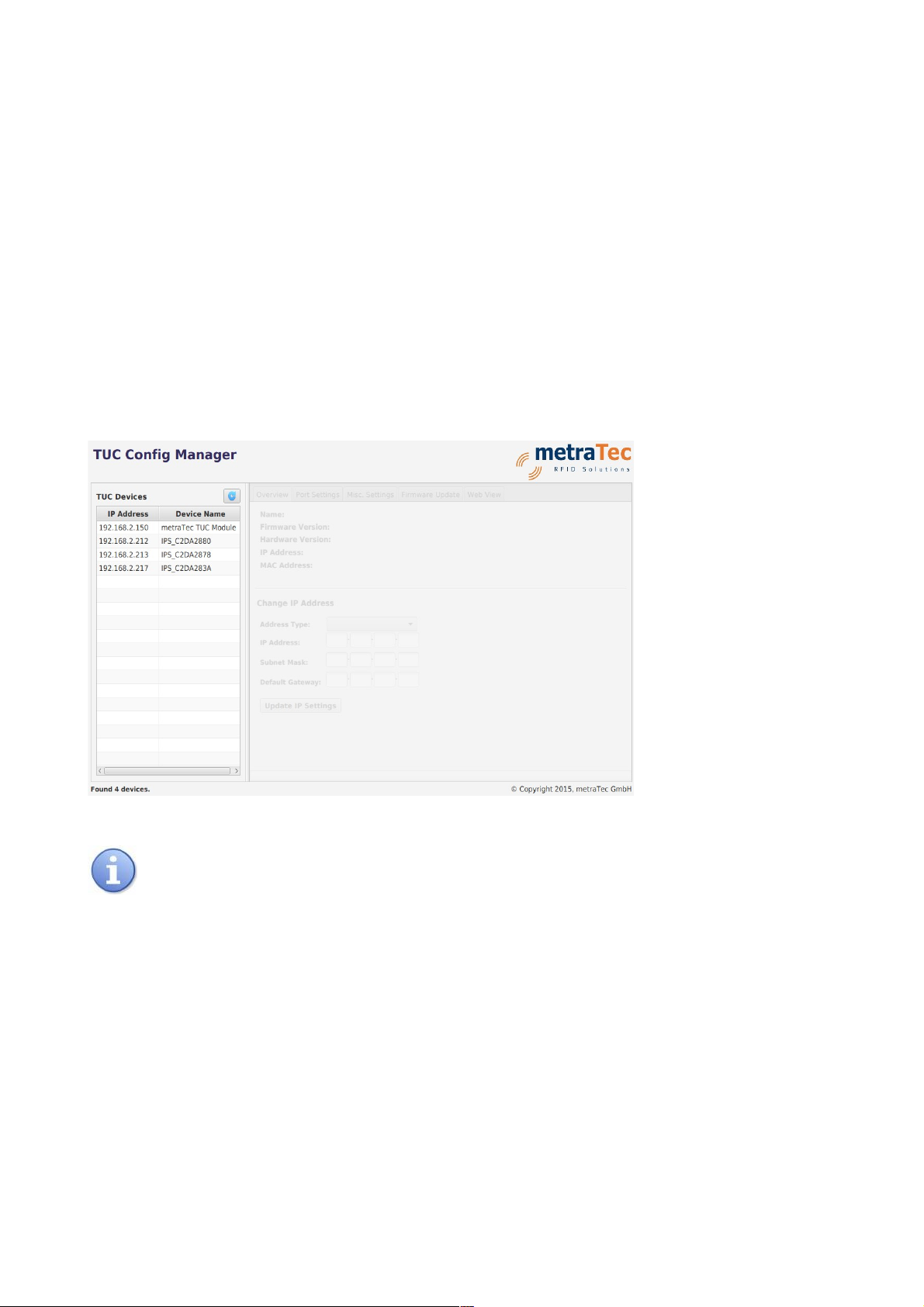
After logging in, the overview page is shown that lists all currently active settings of the TUC
module.
User Guide metraTec TUC Page 5 of 3

Fig. 2: “Overview“ Page
2.2 Network Settings
In the sub menu “Settings” “Network Settings” basic network settings can be adjusted. This is →
mainly the IP address type (either static or dynamic via DHCP/AutoIP) and the static IP settings
which are used by the module to acquire a network address.
Furthermore, the name of the device for identification, e.g. via the Config Manager software, can
be changed here. Also, it is possible to disable the automatic UPnP advertisements on this page.
This helps to lower the network traffic caused by the TUC module – UPnP should still work even
without advertisements.
Fig. 3: “Network Settings“ Page
2.3 Port Settings
In the sub menus “Port Settings” and “Port 1 Settings” the configuration of the two UART/GPIO
interfaces (ports) of the TUC module can be changed, as it might be necessary for correct UART
communication with your host controller. It allows you to switch between client and server mode,
Telnet, Raw TCP and Raw UDP transports. Also, the port type can be switched from UART to
User Guide metraTec TUC Page 6 of 3

GPIO, if the corresponding pins should be used as GPIO pins.
Fig. 4: “Port Settings“ Page
2.4 Misc. Settings
Via the sub menu “Misc. Settings” the module can be reset to default. Upon clicking the button,
the default settings will be applied immediately and the device restarts.
Default settings are as follows:
User Guide metraTec TUC Page 7 of 3

Property Default Value
Module Name metraTec TUC Module
UPnP Advertisements Enabled
Address Type Static IP
Static IP Address 192.168.2.239
Subnet Mask 255.255.255.
Default Gateway . . .
Control Shell (Port 4 ) Disabled
Port Type (UART and 1) UART
Baud Rate (UART and 1) 1152 baud
Data Size (UART and 1) 8 bits
Parity (UART and 1) None
Stop Bits (UART and 1) 1 bit
Flow Control (UART and 1) None
Flush Byte (UART and 1) Disabled
Send Timeout (UART and 1) milliseconds
Local Port Number (UART ) 1 1
Local Port Number (UART 1) 1 2
Protocol (UART and 1) Raw TCP
TCP Keepalive Idle Timeout (UART and 1) 5 milliseconds
TCP Keepalive Counter (UART and 1) 5
TCP Keepalive Interval (UART and 1) 1 milliseconds
Mode (UART and 1) Server
Tab. 1: Default settings to be applied on Factory Reset
Further, on this page you can change the web page login password to a custom password.
NOTE
When you change the password it will be sent over the network in plain text. In this
User Guide metraTec TUC Page 8 of 3

moment, everybody “listening” on the network can see the password. Therefore, it
is advisable to change the password only in a secure network.
Fig. 5: “Misc. Settings“ Page
2.5 Applying Settings
Configuration changes submitted using the “Submit” buttons are never applied immediately.
Instead these changes will be “staged” and have to be applied in a separate step. After changing
a setting an “Apply Changes?” box will appear at the bottom of the page. Click “Apply” to apply
all configuration changes (this will restart the TUC module).
Fig. 6: “Apply Changes?” Box
User Guide metraTec TUC Page 9 of 3
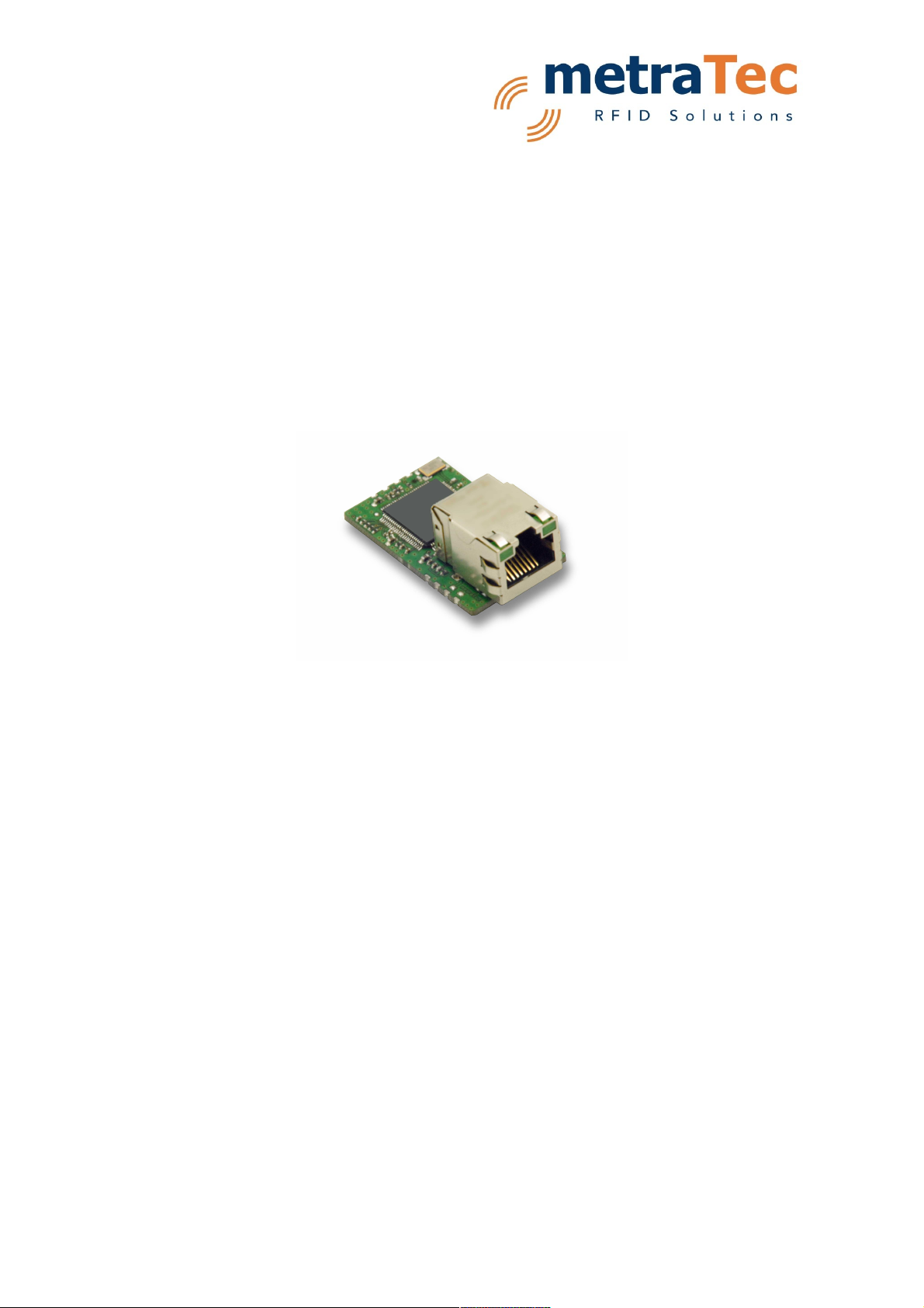
3 TUC Config Manager Software
A comfortable way to configure a TUC module is via the free TUC Config Manager software. It is
also the only tool able to perform firmware upgrades on a TUC module. This Java-based program
works on all PCs with Windows (XP or higher), OS X or Linux with a sufficiently recent Java
Runtime Environment (JRE). The most up-to-date version of the Config Manager can be
downloaded for free from the metraTec website. In addition to the overview of the Config
Manager software provided in this document, you are recommended to refer to the
“README.txt” (contained in the Config Manager's release archive) for software requirements and
troubleshooting hints.
On startup and by clicking the “rescan” button at the upper right of the “TUC Devices” list, the
TUC Config Manager will scan the network for TUC modules. All modules on the same physical
subnetwork as your PC – even those without a valid IP address or an address not routable from
your network – will show up in the list on the left side. Select a device in the list to read out its
configuration data. You can now use the tabs on the right side to view and change the settings of
the module or in order to update the module's firmware.
NOTE
The TUC Config Manager uses UDP broadcast datagrams to scan for modules on
the network. If your firewall or network switch blocks this kind of packet, or you do
not have sufficient privilege to send these packets, the automatic detection will not
work and you cannot use the software. Please make sure that your firewall lets the
Config Manager send and receive all packet types. In doubt, deactivate your
firewall when using the Config Manager and re-activate after use. Attaching a
module adhoc to your PC can make sure that network equipment does not interfere
with the operation of the Config Manager.
3.1 Overview Tab (Network Settings)
In the tab “Overview” you can see and configure some basic parameters of the module – it
roughly corresponds to the web interface's “Network Settings” page. Here you can see the
current firmware version and the MAC address of the device. It is possible to change the IP
User Guide metraTec TUC Page 1 of 3

addressing type of the device (static IP or dynamic via DHCP/AutoIP) and configure the static IP
settings. These are needed for correct communication on an Ethernet network. It is even possible
to set these parameters when the device is otherwise unreachable (due to a network conflict or
similar issues) as long as it is on the same physical subnetwork as your PC.
If you choose “DHCP/AutoIP” as the “Address Type” you will need a working DHCP server in your
network – otherwise the module will use the AutoIP mechanism to aquire an IP while continuing to
look for DHCP servers.
When setting a static IP address, please keep in mind that this has to be a valid address that is
reachable from your subnet and is currently not used by any other device. In doubt, ask your local
administrator for support regarding IP addresses on your network.
After entering the correct settings, click “Update IP Setting” to save these values. The module will
now restart automatically. You should now be able to reach the device at its new address. If you
selected DHCP, just use the Config Manager to find out which IP address it acquired.
3.2 Other Settings
Other settings – like the port configuration, device name etc. - can be performed using the Config
Manager's “Web View” tab. This is simply an embedded browser for the modules's web interface.
After typing in the password, you can use the same navigational items as in the web interface to
set up the TUC module. The layout looks different though, since the web interface will be
optimized for display in the TUC Config Manager.
User Guide metraTec TUC Page 11 of 3
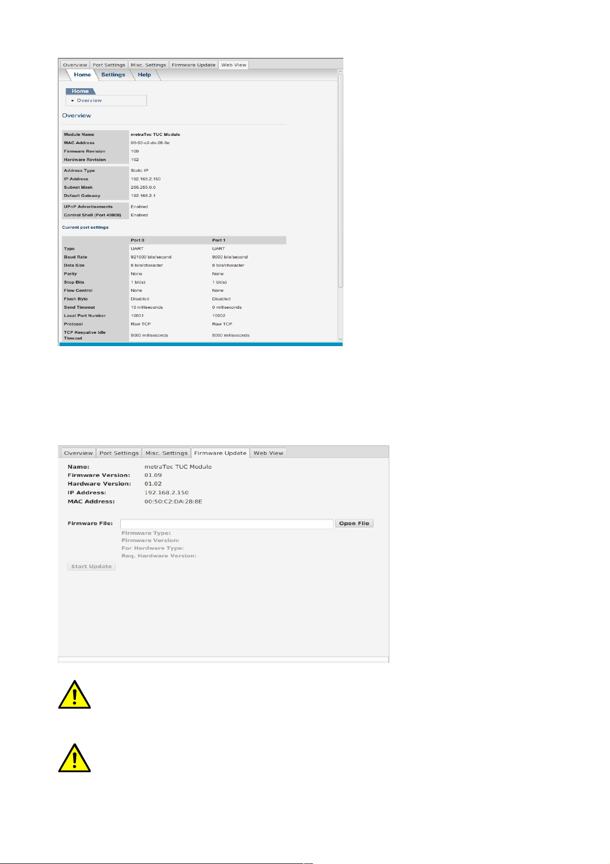
3.3 Firmware Update Tab
The firmware of the TUC module can be updated easily using the tab “Firmware Update”.
Firmware images are to be found on the metraTec web page free of charge. To perform a
firmware upgrade, first select the downloaded firmware image by clicking “Open File”. Finally,
you can click “Start Update” to start the procedure.
ATTENTION
Only use firmware updates that are programmed by metraTec. Do not edit changes
to the file you downloaded. Even an update that was correctly checked by the
bootloader can lead to malfunctioning hardware if changed manually.
ATTENTION
Interrupting the firmware upgrade, disconnecting the device while it is in progress
User Guide metraTec TUC Page 12 of 3

or powering off the device may leave the module in an unusable and unrecoverable
state. Only TUC modules shipped since 2 15 have a special built-in recovery
mechanism that allows you to recover modules which could not be updated
successfully. If this happens, the Config Manager will show these modules as “TUC
Bootloader” in the device list. It is possible to assign an IP address manually and
repeat the upgrade procedure on these devices.
User Guide metraTec TUC Page 13 of 3

4 Control Shell via TCP or UART 1
In addition to the graphical configuration possibilities documented above, the TUC module can
be configured and controlled via control commands. This mode allows the device to be
configured programmatically. Configuration via direct commands (e.g. a configuration script) is
also useful for automatic configuration during the start of operation. The Appendix gives a
summary of direct commands.
For sending the control commands to the device via TCP, the TCP control shell must already be
enabled in the module's configuration (it is disabled by default). This can be achieved on the
“Misc. Settings” page of the web interface. TCP connections to the control shell must be
established on port 4 . There can only be a single TCP connection on port 4 at a time.
To use the control shell interactively, you may use the program “metraTerm” which can be
downloaded free of charge from the metraTec web page. To connect with “metraTerm”, choose
“Ethernet” in its “Connection Settings”. Type in the TUC's IP address (it can also be located
automatically using the “Get” button) and choose 4 as the “TCP Port”. Clicking “Start” in
metraTerm's main window establishes a connection and you can send commands by typing them
in the left part of the window and pressing Enter.
Alternatively, control commands can be sent to the device via UART 1. Thus, configuration of the
TUC module can be done from the host board with the settings directly integrated into the
custom firmware and user interface. For using this feature, the string“metraCFG” (without the
quotes and terminated by a carriage return) has to be sent via UART 1 to the device during the
first five seconds after start up (9,6 ; 8; N; 1).
This command will be affirmed by the module by the string “ACK” (again followed by a carriage
return character). The UART connection will then be open for access. Some of the direct
commands are only valid via TCP (commands changing the port type and using GPIO pins). This
should prevent unwanted interruption of the UART communication. Without receiving the correct
sequence of characters during five seconds after start up, connecting via UART is no longer
possible and port 1 will assume its ordinary role.
4.1 GPIO Control
Programming of the GPIOs is only possible using the TCP control commands. With the SPT
command, the port type (UART or GPIO) is defined. All four pins of one UART interface are
configured as GPIOs in one go.
Status of the GPIOs can be get and set by the direct commands RIP (Read Input Pin) and WOP
(Write Output Pin). Direction of the signal (Input or Output) will be set dynamically depending on
the given command. The Appendix lists the commands with their specific effects.
User Guide metraTec TUC Page 14 of 3

5 Appendix: Control Commands
In the following, the control commands for communication and configuration of the device via
TCP and UART 1 will be listed. Each command will be terminated by a Carriage Return (<CR>).
The module replies with line-by-line answers each ending with a CR.
5.1 PING
The command PING tests the connection to the device. For a valid connection, the module
answers with“OK!“.
Command:
PING<CR>
Parameter:
none
Answer:
OK!<CR>
5.2 REV
The revision command gives information about the firmware version of the module.
Command:
REV<CR>
Answer:
<Type 16 characters><minimum hardware version><firmware version><CR>
Example: TCP_UART_CONV 1 2 11
5.3 RHR
The command Read Hardware Revision gives the version of the hardware used.
Command:
RHR<CR>
Answer:
Example: 1 2<CR>
5.4 RHN
The command Read Hardware Name returns the name of the hardware (padded to 16 characters
with spaces).
Command:
RHN<CR>
Answer:
Example: TUC <CR>
User Guide metraTec TUC Page 15 of 3

5.5 SPT [only available via TCP]
The command SPT defines the port type of the internal micro controller. The IC has two ports that
can be used as UARTs or GPIOs. In UART mode the interface is a serial port. In GPIO mode each
pin (4 per port) can be used as an input or an output pin.
“Port”can be either or 1.
Changes will be applied after executing the command APPLY (as described in 5.17).
Command:
SPT Port Type<CR>
Parameter:
Port: Port Number
Type: UART or GPIO
Answer:
OK!<CR>
UPA<CR> Error: Wrong port number or wrong type (unknown parameter)
5.6 WOP [only available via TCP]
Using the command WOP the status of an Output Pins can be set. At the same time, the pin will
be defined as an Output Pin.
Each pin has an assigned number:
Port Pin am Controller Pin Number for
WOP/RIP
1 1
2 1
3 2
4 3
1 4
2 5
3 6
4 7
Command:
WOP Pin Level<CR>
Parameter:
Pin: Pin Number (ref. Table)
Level: HI for +3.3V or LOW for V
User Guide metraTec TUC Page 16 of 3

Answer:
OK!<CR>
UPA<CR> Wrong pin number or wrong parameter (commands are case-sensitive)
NOS<CR> Port is not configured as GPIO (ref. SPT)
ERR<CR> Pin could not be set
5.7 RIP [only available via TCP]
The command RIP defines a pin as input and reads the current value. The assigned numbers are
the same as for the command WOP.
Command:
RIP Pin<CR>
Parameter:
Pin: Pin Number
Answer:
HI<CR> - high level (3.3V)
LOW<CR> - low level ( V)
UPA<CR> Wrong Pin Number
NOS<CR> Port is not configured as GPIO (ref. SPT)
ERR<CR> Pin could not be read
5.8 SIP
The command SIP enables the assignment of a static IP address to the module. IP address, Subnet
mask and gateway IP consist of each four times three decimal digits (e.g. 192.168.2.1).
Alternatively, the string “DHCP“ commands the module to get an IP address from the DHCP
server (with AutoIP fallback).
Changes will be applied after executing the command APPLY (as described in 5.17).
Command:
SIP STATIC IP address subnet mask gateway IP<CR>
SIP DHCP<CR>
Parameter:
IP address: Static IP address (e.g. 192.168.2.1 )
subnet mask: Static subnet mask (e.g. 255.255.255. )
gateway IP: IP address of the gateway server (e.g. 192.168.2.1)
Answer:
OK!<CR>
ERR<CR> Error: Wrong IP address format
UPA<CR> wrong parameter
User Guide metraTec TUC Page 17 of 3

5.9 UART [only available via TCP]
This command modifies the UART interface configuration.
Changes will be applied after executing the command APPLY (as described in 5.17).
Command:
UART Port Baud-rate Stop-bits Data-size Flow Parity<CR>
Parameter:
Port: Port Number ( or 1)
Baud-rate: decimal (e.g. 1152 ). The baudrate is automatically clipped and rounded to a
baudrate supported by the hardware/software.
Stop-bits: 1 or 2 (bits)
Data-size: 5, 6, 7, 8 (bits)
Flow: NONE or HARDWARE (case sensitive)
Parity: NONE, ODD, EVEN, MARK, SPACE (case sensitive)
Answer:
OK!<CR>
UPA<CR> Error: Wrong port number, invalid parameter, case sensitive wrong input
5.1 UPNP
UPnP is a protocol that allows other computers to find the TUC and query some information about
it (e.g. name of the module). The UPNP command is now only used to enable and disable UPnP
advertisements. The first parameter is deprecated and must always be “8 ”. If NOADS is
specified as the second parameter, UPnP advertisements are disabled, otherwise they will be
enabled.
Changes will be applied after executing the command APPLY (as described in 5.17).
Command:
UPNP 8 <CR>
UPNP 8 NOADS<CR>
Parameter:
Port: Deprecated. Must always be 8 .
Answer:
OK!<CR>
UPA<CR> Error: invalid port number
5.11 FLBYTE
The command FLBYTE sets or disables the “flush byte”. If the “flush byte” is enabled,
downstream traffic on the corresponding UART port is buffered until the “flush byte” is detected
(or any of the other conditions are met) which results in the data to be flushed (ie. sent out) as
soon as possible. There is however no guarantee that every TCP/UDP datagram will end with the
“flush byte” and most operating systems cannot guarantee to deliver the data contained in one
datagram atomically. In protocols permitting it, it is thus useful to optimize the latency between
User Guide metraTec TUC Page 18 of 3

reading a message on the UART and sending it via TCP/UDP – in this case the send timeout can
usually be set higher.
Changes will be applied after executing the command APPLY (as described in 5.17).
Command:
FLBYTE Port<CR>
FLBYTE Port Code<CR>
Parameter:
Port: Port number ( or 1)
Code: The decimal byte value ( to 255) of the “flush byte”. If omitted, the “flush byte” is
disabled.
Answer:
OK!<CR>
UPA<CR> Error: invalid port number or missing parameter
5.12 SENDTT
The SENDTT command configures the send timeout on an UART port. The send timeout is the
maximum time between receiving data on the UART and sending it out (“flushing”) via TCP/UDP.
Setting a low send timeout thus improves the downstream latency. However a low send timeout
might also result in a higher device load and increased network traffic which may result in data
loss.
Changes will be applied after executing the command APPLY (as described in 5.17).
Command:
SENDTT Port Timeout<CR>
Parameter:
Port: Port number ( or 1)
Timeout: The send timeout in milliseconds. A value of effectively disables the send timeout
(data will be sent out as fast as possible).
Answer:
OK!<CR>
UPA<CR> Error: invalid port number or missing parameter
5.13 KEEPALIVE
The KEEPALIVE command configures the TCP keepalive probes on an UART port. When the port
is configured as a TCP client or server, the module will send a number of keepalive probes in a
specified interval on every idle TCP connection in order to detect broken or dead connections.
Dead connections are closed automatically to free up its resources. In server mode, this frees up
one of the 3 connection slots while in client mode, this will result in the TUC trying to reestablish
the connection. Keepalive probes do not result in additional payload traffic and do not demand
any payload traffic – they are a transparent feature of the TCP stack.
The maximum time needed to detect a dead connection is the keepalive idle timeout plus the
keepalive interval multiplied by the keepalive counter.
User Guide metraTec TUC Page 19 of 3

Changes will be applied after executing the command APPLY (as described in 5.17).
Command:
KEEPALIVE Port Idle Counter Interval<CR>
Parameter:
Port: Port number ( or 1)
Idle: Idle timeout in milliseconds. The first probe is sent after this time. If this is specified as ,
keepalive probes are disabled.
Counter: The number of times to send probes before declaring connections dead.
Interval: The interval between sending probes in milliseconds.
Answer:
OK!<CR>
UPA<CR> Error: invalid port number or missing parameter
5.14 CLIENTRIV
This command configures the client reconnect interval for an UART port. This is the time between
connection attempts when operating in TCP client mode. If it is set low, interrupted connections
can be reestablished faster but it can also result in increased network traffic.
Changes will be applied after executing the command APPLY (as described in 5.17).
Command:
CLIENTRIV Port Interval<CR>
Parameter:
Port: Port number ( or 1)
Interval: The interval between connection attempts in milliseconds.
Answer:
OK!<CR>
UPA<CR> Error: invalid port number or missing parameter
5.15 MODE
The command MODE is for setting the parameters that determine how a UART port is exposed
on the network. There are two possibilities:
1. The TUC module operates as a server that peers can connect to. The TUC will listen on the
specified TCP port for incoming connections.
The TUC is able to accept up to 3 concurrent TCP connections per UART port in server
mode. Downstream traffic is mirrored to all connected clients while concurrent upstream
data is output in on the UART in an unspecified order.
2. Alternatively, the module can operate in client mode. By specifying the remote IP address
and port, the TUC can connect to an external server (Telnet or Raw TCP transports).
The Raw UDP transport is only allowed in client mode. When using UDP, there will be no
formal connection establishment, but the TUC will use the specified remote IP and port as
the destination of the datagrams it sends out. Incoming UDP datagrams are accepted from
any source IP as long as they are sent to the correct destination port.
User Guide metraTec TUC Page 2 of 3
Table of contents


