Metrol DPA-3SR1 User manual

DPA-3SR1
Instruction Manual
MASTER SET
OK NG
DPA-3SR1

2
Contents
1. Overview
1-1.Features
2. Specifications
2-1. Absolute maximum ratings
2-2. Specifications table
2-3. Response time characteristics
2-4. Part names and functions
2-5. Electric circuit diagram
2-6. Wiring
3. Operation Preparation
3-1. Fitting mounting
3-2. Body mounting
3-3. Air piping connections
4. Display at Power On
5. Supply Pressure Alarms
6. Modes
6-1. Overview of modes
6-2. Determination mode
6-3. External master set mode
6-4. SMOOTHING set mode
7. Master Setting
7-1. Example of setting master workpiece (same for all modes)
7-2. Master setting via button input (determination mode)
7-3. Master setting via external input (external master set mode)
8. Frequently-asked Questions (FAQs)
. . . . . . . . . . p. 1
. . . . . . . . . . p. 2
. . . . . . . . . . p. 3
. . . . . . . . . . p. 4
. . . . . . . . . . p. 5
. . . . . . . . . . p. 6
. . . . . . . . . . p. 7
. . . . . . . . . . . p. 8
. . . . . . . . . . . p. 9
. . . . . . . . . . . p. 10
. . . . . . . . . . . p. 11
. . . . . . . . . . . p. 12
. . . . . . . . . . . p. 13
. . . . . . . . . . . p. 14
. . . . . . . . . . . p. 15〜p. 16
. . . . . . . . . . . p. 17

1
This machine uses non-contact measurement to measure air pressure, in order to determine gaps
between workpieces and air nozzles at a high level of precision. It compares the current value with a
preset gap master value. If the current value is narrower than the master value, the gap is determined to
be OK. If it is wider, it is determined as NG.
It uses LEDs and signal output to indicate determination results.
The flow passage has three ports, and results are determined independently for each.
The master value is calculated from the port 1 master value, port 2 master value, and port 3 master value.
1-1. Features
①Capable of measuring with high repeat accuracy.
②Displays and outputs determination results independently for each of three ports.
③Can be controlled using buttons or external input.
④Enclosed in an IP67 dust-proof/waterproof structure.
2-1. Absolute maximum ratings
Item
Supply voltage
Input withstand voltage
Output withstand voltage
Output withstand current
Supply pressure
Value
26.4
26.4
26.4
20 each
300
Unit
V
V
V
mA
kPa
(Note) Applying stress exceeding the absolute maximum ratings above may cause serious damage to
internal structural parts.
1.Overview
2. Specifications
OK
OK
OK
Port #1 master value
0
Port1
Port2
Port3
Gap
Port #2 master value Port #3 master value

2
(Note 1) Value obtained under conditions using the recommended air nozzle (p.7). If an air nozzle of a
different shape will be used, verify on the actual machine before deciding.
(Note 2) Value obtained under conditions using the recommended piping. If a different piping diameter will
be used, verify on the actual machine before deciding.
(Note 3) Value obtained under conditions using one nozzle per port. If multiple nozzles per port will be
used, verify on the actual machine before deciding.
(Note 4) Value obtained under conditions using the included leakage unit.
(Note 5) The external shape of the connection tube for the attached leakage unit is Φ6.
A converter is required to connect a tube with an outer shape of Φ4.
Product name
Repeatability (Note 1) - (Note 4)
Guaranteed repeat accuracy range (Note 1) - (Note 4)
Fluid used
Setting pressure
Consumption flow rate
(Note 1) - (Note 4)
Connection bore
Recommended piping
Response speed
Power supply voltage
Current consumption
Input specification
Output specification
Cable
Electrical response speed
Protective structure
Operating temperature range
DPA-3SR1
±
0.5
μm (master value
:
1〜60
μm)
±
1
μm (master value
:
60〜100
μm)
Air Pressure change : within ±1%
1〜100
μm
Dry air (filtered to 5μm)
150
〜
200
kPa
27
ℓ/min
(max)
Rc
1/8
φ
6
×φ
4
φ
4
×φ
2.5
,φ
6
×φ
4
Refer to response time characteristics graph (p.3)
DC
24
V±
10
%
Up to 100
mA
Photocoupler output: Non-voltage output with polarity
DC
24
V±
10
%
Photocoupler output: Non-voltage output with polarity
(collector/emitter floating)
Voltage: Up to 24 VDC±10%
Current: Up to 20 mA
Residual voltage 1.5 V or less (at 15 mA)
Standard length 3m Oil resistance φ
5.5/
16 cores AWG 28
10
ms、
20
ms、
80
ms (can be set in SMOOTHING set mode)
IP
67
0℃−60℃ (no condensation)
2-2. Specifications table
2. Specifications
SUP port
OUT port (Note 5)

3
2. Specifications
2-3. Response time characteristics
The response time is the time it takes for determination output to switch ON once a workpiece has been
brought toward the air nozzle and has stopped moving (with air supplied to the machine). This will vary
depending on factors such as the length and diameter of the piping from the OUT port to the air nozzle,
the seating of the workpiece, and the supplied air pressure.The graphs below show response times when
a workpiece is brought toward the air nozzle at a speed of 10 mm/sec. until the gap is reduced to the
master value minus one (μm), when there is sufficient space between the air nozzle and workpiece.(For
example, if the master is set at 20 μm, the response time is measured when the workpiece has been
moved up to 19 μm.)
Air nozzle
Workpiece
Air
Leakage unit
Piping between OUT port and air nozzle
Precision regulator
Length of piping between OUT port and air nozzle
Workpiece movement speed
Response time[sec]
Master value[μm]
4.5
4
3.5
3
2.5
2
1.5
1
0.5
0
(Note 1) The response times shown in the above graphs are measurement values only and are not guaranteed.
(Note 2) There is no difference in response time by port.
(Note 3) There is no difference in response time by length of piping between the regulator and SUP port.
Gap
●
Common test conditions
●Measurement system
●Response time characteristic graph
Airnozzle
Measurementport
Workpiecemovementspeed
φ1.5
Port 1
10mm/sec
φ4×φ2.5
φ6×φ4
φ4×φ2.5
φ6×φ4
φ4×φ2.5
φ6×φ4
φ4×φ2.5
φ6×φ4
0
20
40
60
80
100
4.5
4
3.5
3
2.5
2
1.5
1
0.5
0
0
20
40
60
80
100
4.5
4
3.5
3
2.5
2
1.5
1
0.5
0
0
20
40
60
80
100
4.5
4
3.5
3
2.5
2
1.5
1
0.5
0
0
20
40
60
80
100
Response time[sec]
Master value[μm]
Response time[sec]
Master value[μm]
Response time[sec]
Master value[μm]
・Length of piping between OUT port and air nozzle
: 1.5m
・Setting pressure
: 150kPa
・Length of piping between OUT port and air nozzle
: 5m
・Setting pressure
: 150kPa
・Length of piping between OUT port and air nozzle
: 1.5m
・Setting pressure
:200kPa
・Length of piping between OUT port and air nozzle
: 5m
・Setting pressure
:200kPa

4
2-4. Part names and functions
2-5. Electric circuit diagram
Item
1. Port #1 LED
2. Port #2 LED
3. Port #3 LED
4. Port #1master set button
5. Port #2 master set button
6. Port #3 master set button
Pressing and holding a button for at least
one second while in measurement mode
will set the master for the applicable port.
Pressing and holding the port 1 master set
button and port 3 master set button at the
same time for at least five seconds while in
measurement mode will switch to
SMOOTHING set mode.
Determination results are displayed while
in determination mode.Input complete can
be verified in external master set mode.
Master set input #1
Master set input #1(0V )
Master set input #2
Master set input #2(0V )
External master set permission input
External master set permission input(0V)
PORT #1 Determination output (collector)
PORT #1 Determination output (emitter)
DC24V
6 .8 k Ω
Supply pressure alarm output (collector)
Supply pressure alarm output (emitter)
0V
6 .8 k Ω
6 .8 k Ω
MASTER SET
OK NG
DPA-3SR1
46
1 3
2
5
2. Specifications
Main circuit
RED
GREEN
LIGHT GREEN
PINK
PURPLE
WHITE
GRAY
YELLOW
BLUE
BROWN
MEDIUM BLUE
LIGHT BLUE
ORANGE
LIGHT ORANGE
LIGHT BROWN
BLACK
PORT #2 Determination output (collector)
PORT #2 Determination output (emitter)
PORT #3 Determination output (collector)
PORT #3 Determination output (emitter)
Description

2-6. Wiring
5
2. Specifications
0V
24V
0V
24V
LoadLoad
Collector
For collector load
(Active low)
For emitter load
(Active high)
OR
Emitter
Collector
Emitter
Connect the output in accordance with the design conditions.
Note: Individually isolate the unused input and output lines.
Description
Power supply
Master #1 can be set by turning
ON for 100 ms while in STOP
mode.
Master #2 can be set by turning
ON for 100 ms while in STOP
mode.
Turns ON while in Measuring mode to move to
STOP mode.
Outputs the master #1 determination in
Measuring mode.
Turns ON when the current value is at or below
master #1.
Turns ON for 200 ms as ACK for the master #1
set in STOP mode.
Outputs the master #2 determination in
measurement mode.
Turns ON when the current value is at or below
master #2.
Turns ON for 200 ms as ACK for the master #2
set in STOP mode.
Outputs the master #3 determination in
measurement mode.
Turns ON when the current value is at or below
master #3.
Turns ON for 200 ms as ACK for the master #3
set in STOP mode.
Turns ON while the supply pressure is normal.
Example load connection
−
Master #3 can be
set by turning ON
for 100 ms
simultaneously
while in STOP
mode.
Color
RED
BLACK
PINK
PURPLE
GREEN
LIGHT
GREEN
WHITE
GRAY
MEDIUM
BLUE
LIGHT
BLUE
YELLOW
BLUE
BROWN
LIGHT
BROWN
ORANGE
LIGHT
ORANGE
Signal
DC24V±10%
0V
Master #1 SET input
Master #1 SET 0V
Master #2 SET input
Master #2 SET 0V
STOP input
STOP 0V
Determination #1
(collector)
Determination #1
(emitter)
Determination #2
(collector)
Determination #2
(emitter)
Determination #3
(collector)
Determination #3
(emitter)
ALARM (collector)
ALARM (emitter)
0V
0V
24V
Input
6.8kΩ

6
①Connect a fitting to either SUP port 1 or 2 in the figure shown below.
Insert a plug (attached) into whichever SUP port is not being used.
②Connect fittings to OUT ports 1 through 3 in the figure shown below.
Insert a plug into any unused OUT ports.
(Note 1) Fittings and OUT port plugs are not attached. They will need to be purchased separately.
(Note 2) Be sure to also use plumber's tape.
3-1. Fitting mounting
3-2. Body mounting
3. Operation Preparation
69
95
34
8
69.1
54
72
Rc1/8
4-M4D6
Cable
OUT port #1
36
8
Port #1 LED
Mounting surface
Port #3 master set button
2622
SUP port #1
● Outer dimension
Use 4-M4 D6 on the mounting surface shown in the figure below to mount to the machine body.
(Note 1) In order to prevent backflow of coolant from the nozzle, mount the body as far above the air
nozzle as possible.
(Note 2) Select a position that ensures that the piping is as short as possible between the OUT port and
air nozzle, and between the SUP port and regulator.
Rc1/8
Port #2 master set button
Port #1 master set button
Rc1/8
OUT port #2
OUT port #3
Rc1/8
Rc1/8
SUP port #2
Port #2 LED
Port #3 LED

7
● Piping example (Note1)(Note3)
Air
* Insert a plug (attached)
if using SUP port 1.
OUT port #1
* Connect piping using
the same method
as OUT port #1.
Air filter (5 μm mesh)
Recommended air filter: AF20-02 (SMC)
Recommended regulator
IR2000(SMC)
PR1000(CKD)
Precision regulator
* Adjust the supply pressure to
a value from 150 kPa to 200 kPa.
(Recommended
diameter: Φ6×Φ4)
SUP port piping
●Recommended nozzle shape (Note 6)
Clamping
Air nozzle
Detected object/Master
Air
Leakage unit
φ1.5 +0.02
0
φ4 ≦
C 0.1〜0.2
(slight chamfering)
5
Refer to the piping example. Connect the precision regulator and air filter to either SUP port 1 or 2, and
connect the air nozzle and leakage unit to OUT ports 1 through 3.
●
Leakage unit shape
(Note 7)
(Note 8)
(Note 4)
φ0.5
34.6
12.5
3-3. Air piping connections
3. Operation Preparation
(Note 1) The precision regulator, air filter, and piping are not attached. They will need to be purchased
separately.
(Note 2) Use a precision regulator. (Repeatability must be within ±0.5%)
(Note 3) Supplying air of 300 kPa or higher to the machine could damage internal structural parts.
Adjust the supply pressure to a value from 150 to 200 kPa before connecting piping.
(Note 4) Do not use devices or fittings which could cause air leaks or resistance on the piping from the
OUT ports to the air nozzle.
(Note 5) The external shape of the connection tube for the attached leakage unit is Φ6. A converter is
required to connect a tube with an outer shape of Φ4.
(Note 6) Air nozzles are not attached. They must be produced by the customer based on the
recommended air nozzle shape.
(Note 7) Install the leakage unit in a location that will not be exposed to coolant and cuttings when air is
stopped.
(Note 8) Ensure that the hole on the leakage unit is not blocked.
Connection tube
external shape
φ6
OUT port #2
OUT port #3
OUT port piping (Note 5)
(Recommended diameter: Φ4×Φ2.5 and Φ6×Φ4)
SUP port #2
SUP port #1
(Note 2)
Connection tube
external shape
φ6

ON (red)
Alarm name
LED display
Port #1LED Port #2 LED Port #3 LED
Applicable LED blinks purple
OFF
OFF
OFF
OFF OFF
ON (red) OFF
OFF
The supply pressure is 100kPa or less
Supply pressure
alarm outout
Supply pressure changes ±10 kPa or
more from when master was set
100kPa alarm
220kPaalarm
±10kPaalarm
Details
The supply pressure is over 200kPa
8
When the power is turned on, the LEDs blink blue and then the machine begins normal operation.
If there is a memory error, the LEDs will blink red when the power is turned on.
The machine cannot be operated normally in this state. Contact us for support.
A supply pressure alarm occurs when the supply pressure falls outside of the specification range.
DPA-3SR1 has the following supply pressure alarms.
(Note) A supply pressure of 150 kPa is set for the master at the factory.
This could trigger the ±10 kPa alarm depending on the pressure being supplied.
Set the master first before use.
4. Display at Power On
5. Supply Pressure Alarms

9
6-1. Overview of modes
6. Modes
Mode
Determination mode
External master
set mode
SMOOTHING
set mode
Description
Compares the master values and current value
and outputs the determination results.The
master can be set via button input. Setting the
master via external input is prohibited.
Stops determination and turns outputs other than
supply pressure alarms OFF.The master can be
set via external input.
Setting via button input is prohibited.
Stops determination and turns all outputs OFF.
The averaged count for pressure measurement
can be changed using by pressing either button.
How to enter the mode
Turn external master set
permission input OFF.
Turn external master set
permission input ON while in
determination mode.
Press and hold the port 1
master set button and port 3
master set button at the same
time for at least five seconds
while in determination mode.
DPA-3SR1 has the following modes.
External master
set mode
Determination
mode
External master set
permission input ON
Port 1 master set button
and port 3 master set button
pressed at same time
for at least five sec.
External master set
permission input OFF
No operation for 3 sec.
or more
SMOOTHING
set mode

10
When the external master set permission input is OFF, the machine switches to determination mode.
While in determination mode, it continuously compares the current value with the preset master value,
and indicates the determination results using the LEDs and outputs.
LED display and output in Measuring mode
Example
Item
Port #1
LED
Port #2
LED
Port #3
LED
Port #1
determination
Port #2
determination
Port #3
determination
Supply
pressure
alarm
Master set complete During supply pressure alarm
6-2.Determination mode
OK
determination
NG
determination
Port #1
blue/lit
↓
blue/blink
Port #2
blue/lit
↓
blue/blink
Port #3
blue/lit
↓
blue/blink
100kPa
alarm
red/blink
220kPa
alarm
red/blink
±10kPa
alarm
Applicable LED
blinking purple
(other LEDs
respond to
determination)
Applicable
output ON
(other LEDs
respond to
determination)
Responds to determination
Responds to supply pressure alarm status
6. Modes
OK determination
Port #1 master value
0
Port #1
Gap
Port #2 master value
Display
Output
OK determination
OK determination
Port #3 master value
Port #2
Port #3
Applicable
output ON
Applicable
output OFF
Applicable
LED ON
(blue)
Applicable
LED ON
(red)
OFF
OFF OFF
OFF
OFF
OFF OFF
OFF
OFF
OFF
OFFOFF
OFF
MASTER SET
OK NG
DPA-3SR1
MASTER SET
OK NG
DPA-3SR1
MASTER SET
OK NG
DPA-3SR1
MASTER SET
OK NG
DPA-3SR1

11
When the external master set permission input is ON, the machine switches to external master set mode.
Outputs other than supply pressure alarms are turned OFF and the master can be set via external input.
The master can be set via external input when all LEDs are blinking blue (supply pressure normal) or
blinking purple (supply pressure changes ±10 kPa or more from when the master was set).
External master set mode LEDs and outputs
6-3. External master set mode
±10kPa
alarm
Port #1
determination
Port #2
determination
Port #3
determination
Supply
pressure
alarm
Supply
pressure
normal Port #1
Item
Port #2 Port #3
Master set complete During supply pressure alarm
100kPa
alarm
220kPa
alarm
Responds to supply pressure
alarm status
6. Modes
Display
Output
Port #1
LED
Port #2
LED
Port #3
LED
Applicable LED
blinking purple
(other LEDs
respond to
determination)
OFF
ON
OFF
OFF
For 200 ms
ON (ACK)
↓
OFF
OFF
OFF
For 200 ms
ON (ACK)
↓
OFF
For 200 ms
ON (ACK)
↓
OFF
OFF
OFF
OFF
OFF
OFF
OFF OFF
OFF
OFF
OFF
red/blink
OFF
OFF
red/lit
blue/blink
red/lit
red/lit
red/lit
OFF OFF OFF
MASTER SET
OK NG
DPA-3SR1

12
SMOOTHING set mode LEDs and outputs
Pressing and holding the port 1 master set button and port 3 master set button at the same time for at least
five seconds while in determination mode will switch to SMOOTHING set mode.
If there is no operation for 3 seconds or more in SMOOTHING set mode, the mode will automatically
switch to determination mode.
Press any of the buttons while in SMOOTHING set mode to switch the averaged count for pressure
measurement from 4 to 16 and then to 64.
The electrical response time will be 10 ms, 20 ms, and 80 ms, respectively.
The averaged count is set to 4 at the factory.
Determination mode
Port 1 master set button and port 3 master set button
pressed at same time for at least five sec.
No operation for 3 seconds or more
Any button pressed
Any button pressed
Any button pressed
Averaged count: 4
Averaged count: 16
Averaged count: 64
6-4. SMOOTHING set mode
Averaged count: 4
red/blink
OFF
Averaged count: 16
purple/blink
OFF
Averaged count: 64
blue/blink
OFF
6. Modes
DisplayOutput
SMOOTHING set mode
Port #1 LED
Port #2 LED
Port #3 LED
Item
Port #1 determination
Port #2 determination
Port #3 determination
Supply pressure alarm

13
(1) If using a shim (2) If using a master workpiece with a gap
Master setting refers to using a master workpiece to set the master value, which is a threshold value
used for determination. The master can be set in determination mode and in external master set mode.
Refer to the table below, as the method for setting the master differs by mode.
Mode
Determination mode
External master set mode
Button input
Y
N
External input
N
Y
ACK output
N
Y
Master setting
(Note 1) The master values are saved even when the power is turned off.
(Note 2) If the measurement system changes, make sure to set the master again.
When setting the master, set a gap to serve as the master value as shown in the examples in the figures
below.
7. Master Setting
7-1. Example of setting master workpiece (same for all modes)
Master workpiece Master workpiece
Shim
Master value
Air
Air
Air nozzle Air nozzle
Master value

Master setting port #1
14
Supply pressure
outside rated range
Press port #1 master set button
when supply pressure is within rated range (Note1)
(Note2)
7. Master Setting
7-2. Master setting via button input (determination mode)
Port #1 LED blue/lit
Port #2 LED OFF
Port #3 LED OFF
Port #1 LED
blue/lit
↓
blue/blink
Press port #1 master set button for at least 1 sec.
Press port #2 master set button
or port #3 master set button
Release port #1 master set button
Master setting
canceled
Release port #1 master set button
External master set permission input OFF
Adjust to supply pressure of 150 to 200 kPa
Completion Completion
Port #1 master set button
100kPa alarm
220kPa alarm
Determination mode
MASTER SET
OK NG
The master can be reset by setting the master workpiece in place and then pressing the button
corresponding to each port for at least 1 second in determination mode.
Refer to the figure below for details.
(Note 1) The master can be set even during a ±10 kPa alarm, if the supply pressure is within the rated range.
(Note 2) The master can be set for port #2 and port #3 by using the same procedure for port #1 and
pressing the corresponding button.The master does not need to be set for port #1, port #2, and port #3 in
any particular order.

15
Supply pressure within rated range (Note1)
7. Master Setting
7-3. Master setting via external input (external master set mode)
Adjust to supply pressure of 150 to 200 kPa
100kPa alarm
220kPa alarm
Supply pressure
outside rated range
Port #1 LED red/lit
Port #2 LED OFF
Port #3 LED OFF
ACK output:
Port #1determination
200ms ON
Send a pulse of
at least 100 ms
to master set input #1
External master set permission input ON
Send a pulse of
at least 100 ms
to master set input #2
Send a pulse of
at least 100 ms
to master set input #1
and master set input #2
simultaneously
Port #1 LED OFF
Port #2 LED red/lit
Port #3 LED OFF
ACK output:
Port #2 determination
200ms ON
Port #1 LED OFF
Port #2 LED OFF
Port #3 LED red/lit
ACK output:
Port #3 determination
200ms ON
Master setting port #1 Master setting port #2 Master setting port #3
Completion Completion
Completion
External master set
mode
The master can be reset by setting the master workpiece in place and then inputting a pulse corresponding
to each port in external master set mode. Refer to the figure below for details.
(Note 1) The master can be set even during a ±10 kPa alarm, if the supply pressure is within the rated
range.
(Note 2) The master does not need to be set for port #1, port #2, and port #3 in any particular order.

16
7. Master Setting
Timing chart
External master set
permission input
Master set input 1
Master set input 2
Port #1
determination output
Port #2
determination output
Port #3
determination output
ON
OFF
ON
OFF
ON
OFF
ON
OFF
ON
OFF
ON
OFF
Determination
mode External master set mode
tin
tin
tw1
tin
td
td
td
tack
tack
Parameter
Time from external master set permission input
start until set input
Set input time (pulse width)
Time from set input completion to set input
ACK output time (pulse width)
Time from set input completion to ACKoutput
MIN
100
100
200
100
MAX
100
220
Unit
ms
ms
ms
ms
ms
tw1
tin
td
tack
tw2
Timing definition
tin
tw2
tw2
tack
Determination
mode

17
8.Frequently-asked Questions (FAQs)
1. Specifications
Q.1-1
A.1-1
2. Wiring
Q.2-1
A.2-1
Q.2-2
A.2-2
Q.2-3
A.2-3
3. Pressure alarm
Q.3-1
A.3-1
Q.3-2
A.3-2
4. Determination mode
Q.4-1
A.4-1
Q.4-2
A.4-2
Q.4-3
A.4-3
Q.4-4
A.4-4
Is distance output as an absolute value?
No. Gaps are determined as being either above or below the master value only. (Refer to p.1)
Should the output line be connected to either the collector or the emitter?
No. This is the photocoupler output and must be connected to both.
Refer to the connection examples shown in "Wiring" (p.5) for information on how to connect it.
Does the output line switch between 24 V and 0 V?
No. This is the photocoupler output so it switches between conducting and isolated.
Refer to the connection examples shown in "Wiring" (p.5) for information on how to connect it.
Does the output line switch between 24 V and 0 V?
Yes. This is the photocoupler output so it does have polarity.
Refer to the connection examples shown in "Wiring" (p.5) for information on how to connect it.
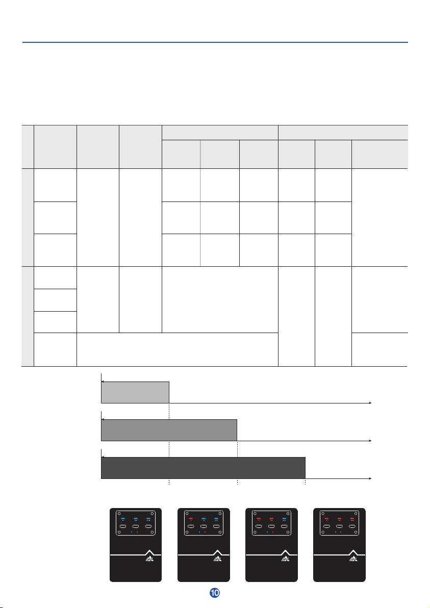
When the machine first starts up, the LEDs blink purple and the supply pressure alarm output is OFF.
Is this a supply pressure alarm?
A supply pressure of 150 kPa is set for the master at the factory.
This could trigger the ±10 kPa alarm depending on the pressure being supplied.
Set the master first before use. (Refer to p. 13)
The pressure gauge shows that the machine is operating within the rated pressure range,
but a pressure alarm is triggered. Is this a failure?
First check for air leaks or blockages in the piping from the pressure gauge and machine,
as well as any connected devices that could be providing resistance.
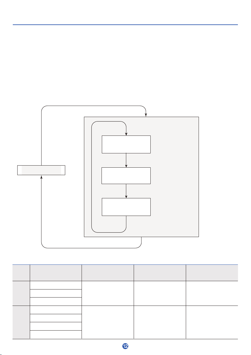
The LEDs and determination output do not change. Is this a failure?
Check whether a pressure alarm has been triggered. (Refer to p. 8)
Check whether the machine is in determination mode. (Refer to p. 9)
The master may not have been set correctly.
Check the conditions and then set the master again.
If checking these shows no problems, check for blockage in the air nozzle, leakage unit,or piping;
air leaks from the sensor to the air nozzle (outside of the leakage unit);
or any devices connected that could be providing resistance.
The LEDs switch to normal but output stays OFF. Is this a failure?
The output cable may not be connected properly or may be disconnected.
Refer to the connection examples shown in "Wiring" (p. 5) for information on how to connect it.
The LEDs switch to normal but output stays ON.
The output cable may not be connected properly.
Confirm that it is connected with proper polarity.
Refer to the connection examples shown in "Wiring" (p. 5) for information on how to connect it.
The machine does not reach the repeat accuracy listed in the specifications table. Why?
The repeat accuracy listed in the specifications table is guaranteed only under recommended conditions.
Refer to the recommended values for gap distance, piping, and air nozzle shape. If different conditions
are being used, verify use on the actual machine to determine whether use is possible.

GM-DPA-3SR1-E-K001
Table of contents
Other Metrol Measuring Instrument manuals
Popular Measuring Instrument manuals by other brands

Wavetronix
Wavetronix smartsensor advance INSTALLER QUICK-REFERENCE GUIDE

Dwyer Instruments
Dwyer Instruments 25 Instructions and operation

Apogee Instruments
Apogee Instruments MQ-210X owner's manual

Honeywell
Honeywell AirAlert 96d Instruction and installation manual

FTE Maximal
FTE Maximal mediaMAX MINI HD user manual

Honeywell
Honeywell BK-G1.6A operating instructions