Metronelec MENISCO ST88 NEO User manual

USER MANUAL
SOLDERABILITY TESTER
METRONELEC
V2.0 –10/2021
6 Avenue Eiffel - 78420 Carrières-sur-Seine
Tél : 01 30 15 20 00
Web : http://www.metronelec.com| Mail : contact@metronelec.com
Page 1sur 83
MENISCO ST88 NEO
Versions :
User guide ST88 Neo
Version 2.0
01/10/2021
Our Solderability Test Systems are designed to provide fast, accurate and
objective measurement of solderability for components, including SMD and
printed circuit boards The system’s output results are expressed in quantitative
units –capillary wetting forces (nM) and wetting meniscus angle (degrees). The
results directly correspond to the solder wettability of the specimen. The
Metronelec solderability systems advance the state of the art of solderability
testing by eliminating the need to use indirect comparisons or subjective
operator interpretations.
Meets requirement of all international standards:
IPC/EIA J-STD 002 1 003
JEDEC MIL 883 L
IEC 68-2-69
IEC 68-2-58
NFC 89-400
User’s standard definition
Specifications
Dimensions: w310 x l500 x h720
Immersion depth: 0.01-15mm by step of 0.01mm
Globule size: 1, 2, 3.2, 4 mm
Languages: English, French, German, Chinese
Force measurement range: 0.1 –40 mN
Force measurement accuracy: 0.001mN

USER MANUAL
SOLDERABILITY TESTER
METRONELEC
V2.0 –10/2021
6 Avenue Eiffel - 78420 Carrières-sur-Seine
Tél : 01 30 15 20 00
Web : http://www.metronelec.com| Mail : contact@metronelec.com
Page 2sur 83
TABLES OF CONTENTS
TABLE OF CONTENTS
Introduction...................................................................................................................6
Physical approach .......................................................................................................6
Surface tensions ......................................................................................................6
Laplace & Young’s equations ....................................................................................6
Balance measurement..............................................................................................7
Wetting force ..........................................................................................................8
Wetting angle..........................................................................................................8
Wetting force divided by perimeter............................................................................9
Solderability................................................................................................................9
Soldering ................................................................................................................9
Solderability testing................................................................................................10
Ageing ..................................................................................................................10
Why ?...................................................................................................................10
Who ?...................................................................................................................10
Dip & look test method...........................................................................................11
Solder bath wetting balance test method .................................................................11
Solder globule wetting balance test method .............................................................11
Components..........................................................................................................11
Substrates............................................................................................................. 12
Alloys....................................................................................................................12
Lead free ..............................................................................................................12
Fluxes...................................................................................................................12
Standards................................................................................................................. 12
NF 89400 ..............................................................................................................12
NF 89400 P ...........................................................................................................13
Mil –Std –883C method 2022................................................................................13
IEC 68-2-69...........................................................................................................14
IPC/ANSI/J-STD-002/3 ...........................................................................................14
User’s specification ................................................................................................14
Utilization ....................................................................................................................15

USER MANUAL
SOLDERABILITY TESTER
METRONELEC
V2.0 –10/2021
6 Avenue Eiffel - 78420 Carrières-sur-Seine
Tél : 01 30 15 20 00
Web : http://www.metronelec.com| Mail : contact@metronelec.com
Page 3sur 83
Start up....................................................................................................................15
Connection............................................................................................................15
Introduction ..........................................................................................................15
User level.............................................................................................................. 17
Main menu............................................................................................................17
Definition of parameters ............................................................................................18
New File................................................................................................................19
Open file...............................................................................................................19
Parameters............................................................................................................20
Measuring solderability of component / pcb................................................................. 26
Components model choice......................................................................................26
Specific components ..............................................................................................27
Coupons ...............................................................................................................27
Video recording.........................................................................................................27
Video capture........................................................................................................28
Image capture.......................................................................................................28
Capture parameters ...............................................................................................28
Video Format.........................................................................................................28
Play video .............................................................................................................29
Video source .........................................................................................................29
Video compression................................................................................................. 29
Measuring the Gamma LV..........................................................................................30
Measuring fluxes & alloys efficiency ............................................................................30
Dip & look test..........................................................................................................31
Start Measure ...........................................................................................................33
Measure cycle...........................................................................................................33
Analysis of results .....................................................................................................34
Display the curve ................................................................................................... 34
Apply standard ......................................................................................................35
Table of values ......................................................................................................35
Zoom / scale (force, angle, time) ............................................................................36
Validate / Invalidate / Open / Print / Delete / Average / Merge ..................................36
Options ....................................................................................................................37
Configuration.........................................................................................................37

USER MANUAL
SOLDERABILITY TESTER
METRONELEC
V2.0 –10/2021
6 Avenue Eiffel - 78420 Carrières-sur-Seine
Tél : 01 30 15 20 00
Web : http://www.metronelec.com| Mail : contact@metronelec.com
Page 4sur 83
Other Spec (specification)....................................................................................... 41
CPK ......................................................................................................................42
Languages ............................................................................................................42
Change password ..................................................................................................43
Printing the measurement ......................................................................................43
Printing result in table ............................................................................................44
Component types for bath module .................................................................................45
TYPE 1 : - RECTANGULAR SAMPLE .............................................................................46
TYPE 2 : - CYLINDRIC SAMPLE...................................................................................47
TYPE 3 : - MULTI RECT. (angular) LEADS ...................................................................48
TYPE 4 : - MULTI CYLINDRICAL LEADS.......................................................................49
TYPE 5 : - PLATED SUBSTRATE SINGLE SIDE..............................................................50
TYPE 6 : - PLATED SUBSTRATE DOUBLE SIDE ............................................................51
TYPE 7 : - CHIPS CAPACITOR ....................................................................................52
TYPE 8 : - CHIPS RESISTOR ......................................................................................53
TYPE 9 : - PARTICULAR LC04/04 CASE .......................................................................54
TYPE 10 : - SOT 23 ...................................................................................................55
TYPE 11 : - SOT 143 .................................................................................................56
TYPE 12 : - FLAT PACK, MQFP100, PQFP, SO ..............................................................57
TYPE 13 : - SOT 89 ................................................................................................... 58
TYPE 14 : - DPACK PACKAGE .....................................................................................59
TYPE 16 : - JLCC, PLCC, CQPJ, SOJ ............................................................................61
TYPE 18 : - DUPONT CONNECTOR SOLDER RESIST.....................................................63
TYPE 19 : - PC BOARD OR COMPONENT PARTIALLY WETTABLE...................................64
TYPE 20 : - DIODE DO4.............................................................................................65
TYPE 21 : - DIODE DO5.............................................................................................66
TYPE 22 : - CHIPS SOLID TANTALE A.........................................................................67
TYPE 23 : - CHIPS SOLID TANTALE B (Obsolete).........................................................68
TYPE 24 : - CHIPS SOLID TANTALE C.........................................................................69
TYPE 25 : -SOLDER PASTE ........................................................................................70
TYPE 26 : - CQPL, MQFP>100....................................................................................71
TYPE 27 : - PCB (TEST PAD & PLATED HOLE) .............................................................72
TYPE 28 : - SAMPLE (PBRC/AVX-4M) ..........................................................................73
TYPE 29 : - CHIPS FILM (LCC) ...................................................................................74

USER MANUAL
SOLDERABILITY TESTER
METRONELEC
V2.0 –10/2021
6 Avenue Eiffel - 78420 Carrières-sur-Seine
Tél : 01 30 15 20 00
Web : http://www.metronelec.com| Mail : contact@metronelec.com
Page 5sur 83
Component types for globule.........................................................................................75
TYPE 1 : - RECTANGULAR SAMPLE .............................................................................76
TYPE 2 : - CYLINDRIC SAMPLE...................................................................................77
TYPE 3 : - COMPLEX SHAPE SAMPLE ..........................................................................78
Servicing .....................................................................................................................79
Unpacking ................................................................................................................79
Installation ...............................................................................................................79
Work station environment ......................................................................................79
Powering on the unit..............................................................................................79
Hardware requirements..........................................................................................80
Installation of the software.....................................................................................81
Daily Maintenance.....................................................................................................81
Solder bath ...........................................................................................................81
Solder globule .......................................................................................................81
Annex A ......................................................................................................................81
PCB wetting test ....................................................................................................... 81

USER MANUAL
SOLDERABILITY TESTER
METRONELEC
V2.0 –10/2021
6 Avenue Eiffel - 78420 Carrières-sur-Seine
Tél : 01 30 15 20 00
Web : http://www.metronelec.com| Mail : contact@metronelec.com
Page 6sur 83
INTRODUCTION
Physical approach
When a solid is partially immersed into a molten alloy bath, it is subject to a set of forces
due to the buoyancy and to the surface tensions which are particularly high at the alloy - flux
interface.
The measurement of the force resultant is representative of the meniscus and, consequently,
of the wetting angle and function of the solderability quality.
We distinguish the three following phases:
•The solid phase (component or coupon),
•The liquid phase (molten alloy),
•The vapor phase (atmospheric air in most cases).
Surface tensions
The molecular interactions of these three phases taken in pairs are surface tensions called:
•SL solid-liquid phases,
•SV solid-vapour phases,
•LV liquid-vapour phases.
Θ the wetting angle is the angle defined by the angle between SL and LV
Laplace & Young’s equations
The balance of those three forces is attained when the liquid which wets the solid forms a
stable meniscus represented by the Young’s relation:
SV + SL + LV = 0
The angle 8 formed by the surface of the solid, gaseous (vapour) and the liquid at their
extreme point of contact is the wetting angle.
Vapor (V)
Solid (S)
Liquid
(L)

USER MANUAL
SOLDERABILITY TESTER
METRONELEC
V2.0 –10/2021
6 Avenue Eiffel - 78420 Carrières-sur-Seine
Tél : 01 30 15 20 00
Web : http://www.metronelec.com| Mail : contact@metronelec.com
Page 7sur 83
Figure 1: meniscus
The projection of the forces upon the “z” axis is written:
The angle 8 directly linked to surface tensions is thus representative of the wetting quality.
The angle 8 becomes smaller when the wetting quality increases.
Note: The wetting angle 8 is conceivable only for alloys in the liquid state.
Balance measurement
As we dip the sample in molten alloy, we create an Archimedean push and a wetting force
then the sensor built in the balance sees these two different forces in the same time, hence
the following equation of the force measured by the balance :
Fr = Fw - Fa
Fr ➔resultant force measured by the balance
Fw ➔wetting force
Fa ➔buoyancy (Archimedean push)
IMPORTANT:
You have to consider the force and the
meniscus angle only when the meniscus
(the curve of the force) is stable.
Before, when the meniscus is moving (climbing)
the values of the force are uncertain.
USER MANUAL
SOLDERABILITY TESTER
METRONELEC
V2.0 –10/2021
6 Avenue Eiffel - 78420 Carrières-sur-Seine
Tél : 01 30 15 20 00
Web : http://www.metronelec.com| Mail : contact@metronelec.com
Page 8sur 83
Wetting force
Knowing Fr we can extract the wetting force Fw from the measurement by adding the
Archimedean push.
Fw = Fr +Fa
From LAPLACE’s law,
Fw = LVlcos
And
Fa = vg
Hence
Fr = LVlcos - vg
Fr ➔resultant force measured (mN)
Fw ➔wetting force (mN)
8 ➔wetting angle
LV
➔liquid-vapour surface tension alloy/flux (mN/mm)
l ➔sample perimeter in the meniscus area (mm)
➔Specific volume of the molten alloy (g/mm3
v ➔immersed sample volume (mm)
g ➔gravitational field (9.81 m/s2)
The other parameters are data fixed in accordance with the testing conditions.
If the value of the surface tension LV, is unknown, operator shall start by determining it as
this value is mandatory for wetting angle and standard limit calculations, for more details see
section “Video recording”.
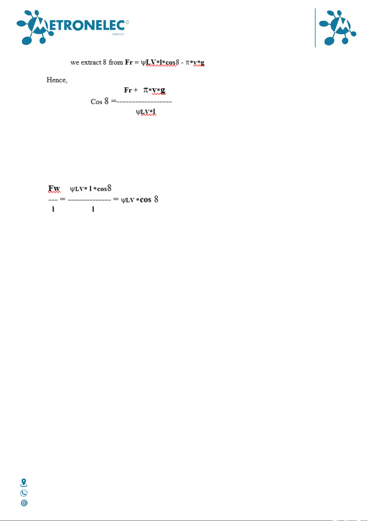
Wetting angle
The wetting angle gives a direct and absolute answer by a simple reading of the value. It is
difficult in case of complex shape to extract the wetting angle.
The software uses dedicated formulas following the shape and the entry angle to extract the
correct wetting angle.
In the general case (component fully wettable, regular shape on “z” axis),
USER MANUAL
SOLDERABILITY TESTER
METRONELEC
V2.0 –10/2021
6 Avenue Eiffel - 78420 Carrières-sur-Seine
Tél : 01 30 15 20 00
Web : http://www.metronelec.com| Mail : contact@metronelec.com
Page 9sur 83
Wetting force divided by perimeter
An alternative way between angle and force is to divide the wetting force by the perimeter
so we obtain a result independent from the perimeter.
Using the same notation, we have :
As LV is constant, this unit is just function of the wetting angle and limited by +LV as cos8
can’t be greater than one.
Solderability
Soldering
Soldering is the assembly of metallic surfaces with the help of a metal or an alloy in the
liquid state.
The liquidus temperature is below these of the metals to joint by wetting. These surfaces are
not reflowed during this process (by opposition to brazing) but are dissolved in the alloy.
Soldering is the main solution used in electronic assembly to provide a good electrical,
mechanical and thermal link with the following advantages:
•Good knowledge of the technology
•Wetting effect
•Very long feed back
•Low cost
•Mass production is easy
•Low temperature
All soldering methods use an alloy and a flux associated in different ways following the
application type:
•Cored solder wire with solid flux
•Wave soldering with liquid flux
•Solder cream reflow with pasty flux

USER MANUAL
SOLDERABILITY TESTER
METRONELEC
V2.0 –10/2021
6 Avenue Eiffel - 78420 Carrières-sur-Seine
Tél : 01 30 15 20 00
Web : http://www.metronelec.com| Mail : contact@metronelec.com
Page 10 sur 83
Solderability testing
The goal is to evaluate the quality of components / soldering ingredients before to use it on
production lines.
We can use solderability test to check components, pcb, alloys, chemicals for soldering or
components productions, etc…
We can’t check all components, so we operate by sampling to measure the « average level »
of solderability. Size of the sampling depends on the amount of components and the degree
of confidence you want to use, all this is just statistic and is defined in quality standards.
Usually, we use batches of ten or twelve components to have a good idea of the quality.
Ageing
To know the solderability of a “fresh component” is not enough…As solderability can evolve
quickly, it is also very important to know, to predict the wettability versus time to warrant
the quality for months.
The ageing of fusible coating creates intermetallic growth; organic deposits have also a
limited shelf life, ageing in general is not good for wettability as the general state of the
surface is degraded.
Solderability shelf life is an important figure to know.
Different standards define conditions of ageing, it is generally an immersion of few hours in
“dry steam”, see standards for more details.
Why ?
The main reason is to avoid over cost due to repair and production destabilization and also
to lead the process.
Predict production results with off line trials.
Components, process approval, pcb or component manufacture (No clean, lead free, etc)
This equipment, defined in standards and meeting all standard requirements is also
mandatory to justify the level of solderability in case of doubt / conflict.
Who ?
Every company involved in soldering from:
•Raw materials suppliers (copper tapes or wires, rosins)
•Lead frames suppliers / formers
•Chemicals suppliers for pcb or component fabrication and assembly.
•Pcb and component manufacturers.
•Assembly companies
•Laboratories and schools

USER MANUAL
SOLDERABILITY TESTER
METRONELEC
V2.0 –10/2021
6 Avenue Eiffel - 78420 Carrières-sur-Seine
Tél : 01 30 15 20 00
Web : http://www.metronelec.com| Mail : contact@metronelec.com
Page 11 sur 83
Dip & look test method
This test, achievable with the ST88 NEO, is only a visual test with no physical measure.
The sample is dipped in defined conditions followed by a manual control visual. Methodology
is binary, just pass or fail no more discrimination. A comparison is not easy… Influence of the
operator in evaluation of the result, subjectivity, repeatability, reproducibility function of the
operator…
Efficient only with larges surfaces or need to use a microscope. See standards for more
information.
Solder bath wetting balance test method
We do a complete soldering with a specimen mounted on a balance and dipped in a bath;
we weight the amount of alloy wetting the specimen. The conditions of test are known and
well standardized.
There is a direct relation between solderability and the mass measured.
The process is computerized so the comparison, historic, and traceability are easy offering a
very good discrimination.
This method is well known worldwide by all standards and companies involved in electronic.
Solder bath method is preferred for conventional components soldered on wave application,
repeated tests (no need to align), gross thermal mass, large components.
Solder globule wetting balance test method
We do a complete soldering with a specimen mounted on a balance and dipped in a globule,
we weight the amount of alloy wetting the specimen. The conditions of test are known and
standardized.
There is no direct relation between solderability and the mass measured but we can proceed
by comparison.
The process is computerized so the comparison, historic, and traceability are easy offering a
very good discrimination.
This method is well known worldwide by some standards and companies involved in
electronic.
Solder globule test method is preferred for local test (on pcb or component) for partially
wettable sample, to limit the Archimedean push.
Components
All types of components can be tested with this machine excepted components already
soldered with balls or columns (BGA, etc). We can check the solderability of BGA before
balling but there is no sense to check the wettability of an alloy.
If the shape is simple, regular in the “z” axis or known in the library, we can apply a model
to define the quality of wetting following the force measured.

USER MANUAL
SOLDERABILITY TESTER
METRONELEC
V2.0 –10/2021
6 Avenue Eiffel - 78420 Carrières-sur-Seine
Tél : 01 30 15 20 00
Web : http://www.metronelec.com| Mail : contact@metronelec.com
Page 12 sur 83
If this is not the case we can test the component by comparison by building our own
reference.
Substrates
Substrates are the base where we solder the component leads and pads.
We have a lot of different base materials and finitions (metallic or organic) on the market.
Preparation is essential for substrate testing, see annex A.
Alloys
Metal or alloy with a melting point below 500 °C (soft soldering) generally based on tin with
addition of lead, silver, antimony, copper, etc.
The alloy is present like a bath or like a preform called globule. Alloys are defined in many
national or international standards.
Lead free
As the ST88 NEO is fully compatible with all type of alloys with melting temperature from
room temperature to 450 °C as standard (600°C by request), there is no limitation for lead
free alloys. No prematured ageing of the pot with any lead free alloy.
Don’t forget to input the right temperature and density to stay in the validity domain of the
formulas !
Fluxes
The flux is a chemical compound applied on metallic surface to help the soldering. The fluxes
used in electronics are defined in many standards like synthetic, no clean, organic non rosin
based, organic…
The fluxes used as standard in solderability are colophony based collected from trees. We
define different type of activities by addition of an activator halided Ex type R Rosin non
activated, RMA Rosin middly activated and RA Rosin activated).
Standards
This chapter describes quickly the spirit of the different standards in use, for further
information, as these texts are protected by copyright; please refer to original text available
on the web (www.ipc.org, www.iec.ch, etc)
The operator can apply all these standards to any curve or batch of curves by a simple right
click on the graph area
NF 89400
This standard defines only the bath method.
The sanction is the value of the wetting angle obtained with the following test conditions :
Ageing : not mandatory

USER MANUAL
SOLDERABILITY TESTER
METRONELEC
V2.0 –10/2021
6 Avenue Eiffel - 78420 Carrières-sur-Seine
Tél : 01 30 15 20 00
Web : http://www.metronelec.com| Mail : contact@metronelec.com
Page 13 sur 83
Flux : type R or RMA (CMA from the NF French standard NF C 90550) Alloy Sn60Pb40 at 235
°C
Immersion speed 20 to 30 mm/s
Immersion depth 4 or 2 mm
Immersion time : time as a function of the component size being admitted that the reference
time is 3 s for small components (including the CMS).
Pre heat : no
Pass / Fail criteria(s) : the solderability quality is classified into four categories according to
the following table
SOLDERABILITY CLASS QUALITY ANGLE VALUE ( ° )
1 EXCELLENT 8 : 30
2 GOOD 8 : 40
3 ADMISSIBLE 8 : 55
4 UNCERTAIN 8 : 55
The experience gained in production and assembly workshops enables the following table to
be drawn up:
Note: if a sample in ten does not fall in the category chosen, one should measure five new
samples which must all be satisfactory.
NF 89400 P
This standard defines only the bath method.
This is a variant of the previous one, we use in this case the force divided by the wettable
perimeter as presented before. The “P” means perimeter.
We can use the wetting force (Fw/mm) extracted from the balance or the resultant force
(Fr/mm) directly from the sensor.
The test conditions are :
Ageing : not mandatory
Flux : type R
Alloy : Sn60Pb40 at 245 °C Immersion speed : 20 to 30 mm/s Immersion depth : 4 or 2
mm.
Immersion time : 5 to 10 s.
Pre heat : no
Pass / Fail criteria(s) : zero crossing time less than 0.59 s (time to across the “x” axis
Time to obtain 2/3 of the maximum force less than 1.0 s
Mil –Std –883C method 2022
This standard defines only the bath method.
This standard is a US military specification, designed for traditional components like DIL
cases.

USER MANUAL
SOLDERABILITY TESTER
METRONELEC
V2.0 –10/2021
6 Avenue Eiffel - 78420 Carrières-sur-Seine
Tél : 01 30 15 20 00
Web : http://www.metronelec.com| Mail : contact@metronelec.com
Page 14 sur 83
The conditions are :
Ageing : yes
Flux : type R or RMA Alloy Sn60Pb40 at 245 °C
Immersion speed 20 to 30 mm/s
Immersion depth 4 or 2 mm
Pre heat : no
Pass / Fail criteria(s) : zero crossing time less than 0.59 s (time to across the “x” axis )
Time to obtain 2/3 of the maximum force less than 1.0 s
IEC 68-2-69
This standard defines both methods bath and globule.
Ageing : defined
Flux : type R, RMA, RA
Alloy : Sn60Pb40 at 235 °C or lead free
Immersion speed : function of the component Immersion depth : function of the
component
Immersion time : 5 to 10 s.
Pre heat : no
Pass / Fail criteria(s) : Buoyancy crossing time.
Time to obtain 2/3 of the maximum force less than 1.0 s
Minimum of force to reach at 2 and 5 s
IPC/ANSI/J-STD-002/3
This standard defines both methods bath and globule. Solderability test procedures for
components and pcb.
Ageing : 3 classes defined
Flux : type R, RMA, RA
Alloy : Sn60Pb40 at 245 °C or lead free at 255°C Immersion speed : function of the
component
Immersion depth : function of the component.
Immersion time : 5 to 10 s.
Immersion angle : 45 to 70 ° Pre heat : no
Pass / Fail criteria(s) : Buoyancy crossing time in less than 1.0 s.
Time to obtain 2/3 of the maximum force less than 1.0 s
Minimum of force to reach at 2 and 5 s
User’s specification
The user can define is own specification pass / fail criteria in time, level of force, time to
buoyancy, etc all criteria defined in standards. See section Utilization.

USER MANUAL
SOLDERABILITY TESTER
METRONELEC
V2.0 –10/2021
6 Avenue Eiffel - 78420 Carrières-sur-Seine
Tél : 01 30 15 20 00
Web : http://www.metronelec.com| Mail : contact@metronelec.com
Page 15 sur 83
UTILIZATION
Start up
Connection
Introduction
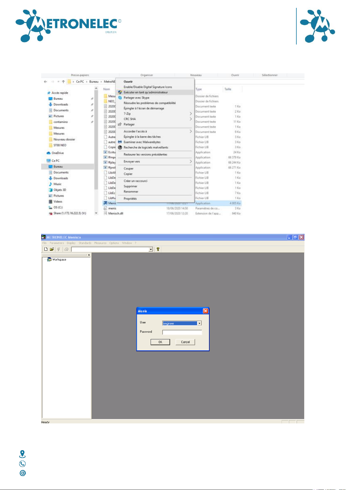
The Menisco icon should be on the desktop or you can find it by Start Menis or Menisco.
On first installation (you will have a direct icon to do it), it is interesting to have the
presentation of Motor Control window appearing. For this just select in the file where it is
installed the Menis.exe file and change the last line from 0 to 1 as shown on the image
below
USER MANUAL
SOLDERABILITY TESTER
METRONELEC
V2.0 –10/2021
6 Avenue Eiffel - 78420 Carrières-sur-Seine
Tél : 01 30 15 20 00
Web : http://www.metronelec.com| Mail : contact@metronelec.com
Page 16 sur 83
Then launch the software by right clicking on the Menis.exe and selecting “Launch under
administrator mode”.
With the mouse click on the Menisco icon and you must obtain the following screen :

USER MANUAL
SOLDERABILITY TESTER
METRONELEC
V2.0 –10/2021
6 Avenue Eiffel - 78420 Carrières-sur-Seine
Tél : 01 30 15 20 00
Web : http://www.metronelec.com| Mail : contact@metronelec.com
Page 17 sur 83
User level
You must choose your user level Engineer or Operator, only the Engineer has a full access to
the software; the Operator has a limited access. The first password is “secret” you can
change it only is Engineer mode, the password is used only for the Engineer mode.
You don’t need to use a password for the Operator mode.
Main menu
After confirmation of the password, the following window appears
Use the arrow keys or the mouse to select the items wanted corresponding to the type of
test to do.

USER MANUAL
SOLDERABILITY TESTER
METRONELEC
V2.0 –10/2021
6 Avenue Eiffel - 78420 Carrières-sur-Seine
Tél : 01 30 15 20 00
Web : http://www.metronelec.com| Mail : contact@metronelec.com
Page 18 sur 83
Startup user interface:
MEASURING FLUX SURFACE TENSION
Select this line in order to measure the surface tension of a couple FLUX / ALLOY, see
section 2.3.
MEASURING COMPONENTS SOLDERABILITY
Select this line in order to measure the component or pcb solderability, see next section for
more details.
MEASURING FLUX EFFICIENCY
Select this line in order to measure flux efficiency using sample of polluted copper with
determined grades, see section Video Recording.
MEASURING WITH SOLDER PASTE
Select this line in order to measure the efficiency of solder paste, using samples of polluted
copper with determined grades, and solderability of SMD components. Option not yet
available with ST88 NEO.
DIP AND LOOK
Select this line in order to check visually the solderability (visual inspection, no weight
measurement)
Definition of parameters
Prior to make any measurement, the operator must define the file where the data will be
stored, for that we can create a new file or open an existing file.
USER MANUAL
SOLDERABILITY TESTER
METRONELEC
V2.0 –10/2021
6 Avenue Eiffel - 78420 Carrières-sur-Seine
Tél : 01 30 15 20 00
Web : http://www.metronelec.com| Mail : contact@metronelec.com
Page 19 sur 83
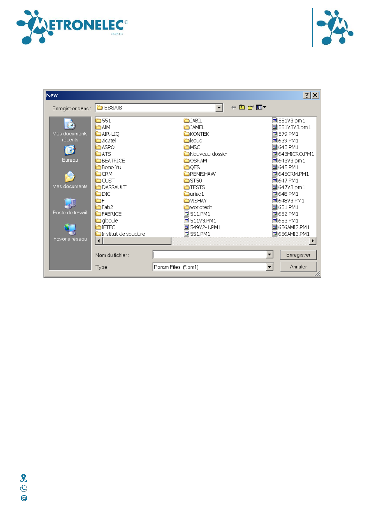
New File
Open the menu File and choose New, or click on the white page icon, then you obtain the
following window
Select a directory or make a directory on your hard disk or on a accessible network drive.
Give a new name and confirm by enter or Save button.
Open file
Open the menu File and choose Open, or click on the open icon, then you obtain the
following window.
Select the directory and file to open on your hard disk or on a accessible network drive.
Confirm by enter or Open button.

USER MANUAL
SOLDERABILITY TESTER
METRONELEC
V2.0 –10/2021
6 Avenue Eiffel - 78420 Carrières-sur-Seine
Tél : 01 30 15 20 00
Web : http://www.metronelec.com| Mail : contact@metronelec.com
Page 20 sur 83
Parameters
Before to start test, check the parameters definition by opening the Parameters Menu and
Next Measure Parameters.
Table of contents


