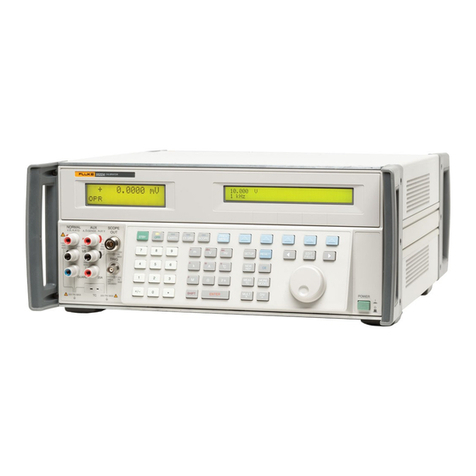
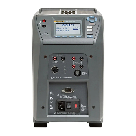
Fluke 5730A Use and care manual

August 2014
© 2014 Fluke Corporation. All rights reserved. Specifications are subject to change without notice.
All product names are trademarks of their respective companies.
5730A
Multifunction Calibrator
Calibration Manual

LIMITED WARRANTY AND LIMITATION OF LIABILITY
Each Fluke product is warranted to be free from defects in material and workmanship under
normal use and service. The warranty period is one year and begins on the date of shipment.
Parts, product repairs, and services are warranted for 90 days. This warranty extends only to the
original buyer or end-user customer of a Fluke authorized reseller, and does not apply to fuses,
disposable batteries, or to any product which, in Fluke's opinion, has been misused, altered,
neglected, contaminated, or damaged by accident or abnormal conditions of operation or
handling. Fluke warrants that software will operate substantially in accordance with its functional
specifications for 90 days and that it has been properly recorded on non-defective media. Fluke
does not warrant that software will be error free or operate without interruption.
Fluke authorized resellers shall extend this warranty on new and unused products to end-user
customers only but have no authority to extend a greater or different warranty on behalf of Fluke.
Warranty support is available only if product is purchased through a Fluke authorized sales outlet
or Buyer has paid the applicable international price. Fluke reserves the right to invoice Buyer for
importation costs of repair/replacement parts when product purchased in one country is submitted
for repair in another country.
Fluke's warranty obligation is limited, at Fluke's option, to refund of the purchase price, free of
charge repair, or replacement of a defective product which is returned to a Fluke authorized
service center within the warranty period.
To obtain warranty service, contact your nearest Fluke authorized service center to obtain return
authorization information, then send the product to that service center, with a description of the
difficulty, postage and insurance prepaid (FOB Destination). Fluke assumes no risk for damage in
transit. Following warranty repair, the product will be returned to Buyer, transportation prepaid
(FOB Destination). If Fluke determines that failure was caused by neglect, misuse, contamination,
alteration, accident, or abnormal condition of operation or handling, including overvoltage failures
caused by use outside the product’s specified rating, or normal wear and tear of mechanical
components, Fluke will provide an estimate of repair costs and obtain authorization before
commencing the work. Following repair, the product will be returned to the Buyer transportation
prepaid and the Buyer will be billed for the repair and return transportation charges (FOB
Shipping Point).
THIS WARRANTY IS BUYER'S SOLE AND EXCLUSIVE REMEDY AND IS IN LIEU OF ALL
OTHER WARRANTIES, EXPRESS OR IMPLIED, INCLUDING BUT NOT LIMITED TO ANY
IMPLIED WARRANTY OF MERCHANTABILITY OR FITNESS FOR A PARTICULAR PURPOSE.
FLUKE SHALL NOT BE LIABLE FOR ANY SPECIAL, INDIRECT, INCIDENTAL, OR
CONSEQUENTIAL DAMAGES OR LOSSES, INCLUDING LOSS OF DATA, ARISING FROM
ANY CAUSE OR THEORY.
Since some countries or states do not allow limitation of the term of an implied warranty, or
exclusion or limitation of incidental or consequential damages, the limitations and exclusions of
this warranty may not apply to every buyer. If any provision of this Warranty is held invalid or
unenforceable by a court or other decision-maker of competent jurisdiction, such holding will not
affect the validity or enforceability of any other provision.
Fluke Corporation
P.O. Box 9090
Everett, WA 98206-9090
U.S.A.
Fluke Europe B.V.
P.O. Box 1186
5602 BD Eindhoven
The Netherlands
11/99
OPERATOR SAFETY
SUMMARY
WARNING
HIGH VOLTAGE
is used in the operation of this equipment
LETHAL VOLTAGE
may be present on the terminals, observe all safety precautions!
To prevent electrical shock hazard, the operator should not electrically contact
the output HI or sense HI terminals or circuits connected to these terminals.
During operation, lethal voltages of up to 1100 V ac or dc may be present on
these terminals.
When the nature of the operation permits, keep one hand away from
equipment to reduce the hazard of current flowing through vital organs of the
body


i
Table of Contents
Title Page
Introduction............................................................................................ 1
How to Contact Fluke Calibration.......................................................... 2
Safety Information ................................................................................. 3
Symbols................................................................................................. 4
Specifications ........................................................................................ 4
Specification Confidence Levels........................................................ 4
Use of Absolute and Relative Specifications ..................................... 5
Use of Secondary Performance Specifications ................................. 5
General Specifications .......................................................................... 5
Electrical Specifications......................................................................... 7
AC Voltage Specifications ................................................................. 9
Resistance Specifications.................................................................. 15
DC Current Specifications ................................................................. 19
AC Current Specifications ................................................................. 21
Wideband AC Voltage (Option 5700-03) Specifications.................... 24
52120A Specifications when Operated with the 5730A..................... 25
52120A Electrical Performance Limits............................................... 25
Operated within 5730A Control Loop (all current ranges) ................. 26
Coverage factor k=2.58 (99 % confidence level)........................... 26
Coverage factor k=2.00 (95 % confidence level)........................... 26
52120A/COIL 3 KA 25-Turn Coil ....................................................... 27
52120A/COIL 6 KA 50-Turn Coil ....................................................... 28
Product Calibration................................................................................ 29
The Artifact Calibration Process ........................................................ 29
Establish Traceability......................................................................... 30
Calibration Reports............................................................................ 30
Range Adjustment ............................................................................. 30
DC Zero................................................................................................. 31
Run DC Zeros.................................................................................... 31
DC Zeros Reminder........................................................................... 31
Calibration Procedures.......................................................................... 32
Calibration Security Passcode........................................................... 32
Artifact Calibration ............................................................................. 32
When to Adjust Product Uncertainty.................................................. 33
Main Output Calibration Procedure ................................................... 34
Range Adjustment................................................................................. 37

5730A
Calibration Manual
ii
Calibrate the Wideband AC Module (Option 5700A-03)........................ 40
Wideband Flatness Calibration Procedure............................................ 42
Calibration Check .................................................................................. 43
Develop a Performance History............................................................. 44
Save Calibration Reports ...................................................................... 45
Calibration Shift Results .................................................................... 45
Calibration Check Shift Results ......................................................... 46
Raw Data Results.............................................................................. 46
Full Verification...................................................................................... 47
Required Equipment for All Tests...................................................... 47
Warmup Procedure for All Verification Tests..................................... 47
Determine Specification Limits for other Calibration Intervals ........... 48
Applying Guardbands to Specification Limits .................................... 49
Resistance Verification Test .............................................................. 51
Verify 0 Ω, 1 Ω, and 1.9 Ω............................................................. 52
Verify 10 Ωthrough 19 MΩ............................................................ 53
Verify 100 MΩ................................................................................ 56
DC Voltage Verification Test ............................................................. 56
DC Zero Test ................................................................................. 57
Self-Calibrate a Fluke 752A Divider with a Fluke 8508A
as the Null Detector ....................................................................... 58
DC Voltage Test at Decade Values............................................... 62
DC Voltage Test at 19 Volts .......................................................... 66
Direct Current Verification Test ..................................................... 68
AC Voltage Frequency Accuracy Test............................................... 71
AC Voltage Verification Test.............................................................. 72
Alternating Current Verification Test.............................................. 76
2 mA to 2 A Ranges ...................................................................... 77
200 μA Range................................................................................ 78
Wideband Frequency Accuracy Test................................................. 82
Wideband AC Voltage Module Output Verification............................ 82
Wideband Output Accuracy at 1 kHz Test............................................. 83
Wideband Output Flatness Test............................................................ 84
General Maintenance ............................................................................ 89
Clean the Exterior.............................................................................. 89
Fuse Replacement ............................................................................ 89
Clean the Air Filter............................................................................. 91
User-Replaceable Parts ........................................................................ 92

iii
List of Tables
Table Title Page
1. Symbols..................................................................................................... 4
2. Standards for Calibration........................................................................... 33
3. List of Required Equipment for Main Output ............................................. 48
4. Required Test Equipment.......................................................................... 51
5. 0 Ω, 1 Ω, 1.9 ΩVerification ....................................................................... 52
6. 10 Ωthrough 19 MΩVerification............................................................... 55
7. Required Equipment for DC Voltage Tests ............................................... 56
8. DC Zero Volt Verification........................................................................... 58
9. DC Voltage Test at Decade Values Verification........................................ 63
10. 19 V DC Verification .................................................................................. 66
11. Required Equipment for Direct Current Test ............................................. 68
12. DC Current Accuracy Verification.............................................................. 70
13. AC Voltage Frequency Accuracy Test Record.......................................... 71
14. Equipment Required for AC V Output Level Tests.................................... 72
15. 5790A Adjustment Counts......................................................................... 73
16. Equipment Required for AC Current Test ................................................. 76
17. AC Current 2 mA to 2 A Verification.......................................................... 79
18. AC Current 200 μA Accuracy Test Record................................................ 81
19. Equipment Required for Testing and Calibrating the Wideband Option.... 82
20. Wideband Adjustment Tolerance .............................................................. 84
21. Wideband Frequency Accuracy Testi Record ........................................... 85
22. Wideband Accuracy at 1 kHz Test Record................................................ 85
23. Wideband Flatness Test Record ............................................................... 86
24. Wideband Absolute Error 10 Hz to 500 kHz.............................................. 88
25. Replacement Fuses .................................................................................. 90
26. User-Replaceable Parts ............................................................................ 92

5730A
Calibration Manual
iv

v
List of Figures
Figure Title Page
1. 732B External Calibration Connections..................................................... 34
2. 742A-1 and 742A-10 k External Calibration Connections ......................... 35
3. 220 V DC Range Calibration Connections ................................................ 39
4. Wideband Module Calibration Connection ................................................ 40
5. Wideband Flatness Calibration Connections ............................................ 42
6. Test Limits Established by Guardbanding................................................. 50
7. 0 Ω, 1 Ω, 1.9 ΩResistance Verification..................................................... 53
8. 10 Ωthrough 19 MΩResistance Verification ............................................ 54
9. Zero Null Detector Connection .................................................................. 61
10. Zero Null Detector Connections s ............................................................. 64
11. DC Voltage Calibration Connection........................................................... 65
12. 19 V DC Verification Connections ............................................................. 67
13. Direct Current Accuracy Test Connections ............................................... 69
14. 1 MHz Low Pass Filter .............................................................................. 71
15. AC Voltage Test Setup.............................................................................. 72
16. 2 mA to 2 A AC Current Verification Connections..................................... 77
17. 200 μA Range Alternating Current Test Setup.......................................... 78
18. Wideband Accuracy at 1 kHz Test Setup.................................................. 83
19. Wideband Flatness Test Setup ................................................................. 84
20. Access the Fuse........................................................................................ 90
21. Air Filter Access ........................................................................................ 91
22. User-Replaceable Parts ............................................................................ 93

5730A
Calibration Manual
vi

1
Introduction
The Fluke Calibration 5730A Calibrator (the “Product” or the “Calibrator”) can
calibrate a wide variety of electrical measurement instruments. The Product
maintains a high accuracy over a wide ambient temperature range. This
accuracy lets the Product test instruments in any environment, and eliminates the
restrictions to calibrate only in a temperature-controlled standards laboratory.
The Product can calibrate precision multimeters that measure ac or dc voltage,
ac or dc current, and resistance. The Product also is available with a Wideband
AC Voltage option which extends this workload to include RF voltmeters.
This manual contains specifications, calibration procedures, and verification
procedures. The Product is a fully-programmable precision source of:
•DC voltage to 1100 V
•AC voltage to 1100 V, with output available from 10 Hz to 1.2 MHz
•AC and DC current to 2.2 A, with output available from 10 Hz to 10 kHz
•Resistance in values from a short (0 Ω) to 100 MΩ
•Optional wideband ac voltage from 300 μV to 3.5 V into 50 Ω(-57 dBm to
+24 dBm), 10 Hz to 30 MHz
Features of the Product include:
•Internal environmentally-controlled references that let the Product maintain
full performance over a wide ambient temperature range.
•Automatic meter error calculation obtained through the use of a simple output
adjust knob.
•Keys that multiply and divide the output value by 10. This simplifies work on
meters with calibration points at decade multiples of a fraction of full-scale.
•Programmable entry limits used to restrict the levels that can be entered into
the Product. This prevents access to levels that may be harmful to equipment
or personnel.
•Continuous display of Product specifications at the selected operation point,
calibration interval, and specification confidence level.
•An auxiliary current binding post to calibrate meters with separate current
inputs without the need to move cables.
•Real-time clock and calendar for date stamping reports and reminders issued
to perform the dc zeros calibration procedure within the required interval.
•Offset and scaling modes that simplify linearity tests of multimeters.

5730A
Calibration Manual
2
•Variable phase reference signal output and phase-lock input.
•Interface for the Fluke Calibration 5725A Amplifier.
•Interface for the Fluke Calibration 52120A Amplifier.
•Standard IEEE-488 (GPIB) interface, that complies with ANSI/IEEE
Standards 488.1-1987 and 488.2-1987.
•EIA/TIA-574 Standard RS-232 serial data interface for remote control of the
Product.
•Universal Serial Bus (USB) 2.0 high-speed interface device port for remote
control of the Product.
•Integrated 10/100/1000BASE-T Ethernet port for network connection remote
control of the Product.
•USB Host port to save calibration reports to a flash drive.
•Extensive internal self-testing and diagnostics of analog and digital functions
•Visual Connection Management output terminals illuminate to help show
correct cable connection configurations.
•Soft Power - automatic selection of line voltage/frequency.
•LCD Color VGA display with touch panel overlay.
•A traceable calibration procedure for all modes and ranges that requires only
10 V, 1 Ω, and 10 kΩexternal standards, with only occasional independent
verification.
•Automated calibration check that provides added confidence between
calibration recalls, and data that can be used to document and characterize
Product performance between calibration recalls.
How to Contact Fluke Calibration
To contact Fluke Calibration, call one of the following telephone numbers:
•Technical Support USA: 1-877-355-3225
•Calibration/Repair USA: 1-877-355-3225
•Canada: 1-800-36-FLUKE (1-800-363-5853)
•Europe: +31-40-2675-200
•Japan: +81-3-6714-3114
•Singapore: +65-6799-5566
•China: +86-400-810-3435
•Brazil: +55-11-3759-7600
•Anywhere in the world: +1-425-446-6110
To see product information or download manuals and the latest manual
supplements, visit Fluke Calibration’s website at www.flukecal.com.
To register your product, visit http://flukecal.com/register-product.

Multifunction Calibrator
Safety Information
3
Safety Information
A Warning identifies conditions and procedures that are dangerous to the user.
A Caution identifies conditions and procedures that can cause damage to the
Product or the equipment under test.
Warnings
To prevent possible electrical shock, fire, or personal injury:
•Read all safety information before you use the Product.
•Carefully read all instructions.
•Do not use the Product around explosive gas, vapor, or in
damp or wet environments.
•Use this Product indoors only.
•Do not put the Product where access to the mains power
cord is blocked.
•Use only the mains power cord and connector approved for
the voltage and plug configuration in your country and rated
for the Product.
•Replace the mains power cord if the insulation is damaged
or if the insulation shows signs of wear.
•Make sure the ground conductor in the mains power cord is
connected to a protective earth ground. Disruption of the
protective earth could put voltage on the chassis that could
cause death.
•Do not use an extension cord or adapter plug.
•Do not operate the Product with covers removed or the case
open. Hazardous voltage exposure is possible.
•Do not use the Product if it operates incorrectly.
•Do not connect to live output terminals. The Product can
supply voltages that can cause death. Standby mode is not
sufficient to prevent electrical shock.
•Do not apply more than the rated voltage, between the
terminals or between each terminal and earth ground.
•Use only cables with correct voltage ratings.
•Do not touch exposed metal on banana plugs, they can have
voltages that could cause death.
•Do not touch voltages >30 V ac rms, 42 V ac peak, or 60 V dc.
•Use the Product only as specified, or the protection
supplied by the Product can be compromised.
•Use only specified replacement fuses.
•Have an approved technician repair the Product.

5730A
Calibration Manual
4
Symbols
The symbols shown in Table 1 can be found in this manual or on the Product.
Table 1. Symbols
Symbol Definition Symbol Definition
Risk of Danger. Important information.
See Manual. Hazardous voltage. Risk of electric
shock.
This product complies with the WEEE
Directive (2002/96/EC) marking
requirements. The affixed label
indicates that you must not discard this
electrical/electronic product in domestic
household waste. Product Category:
With reference to the equipment types
in the WEEE Directive Annex I, this
product is classed as category 9
"Monitoring and Control
Instrumentation" product. Do not
dispose of this product as unsorted
municipal waste. Go to Fluke’s website
for recycling information.
Conforms to European Union directives
Conforms to relevant North American
Safety Standards. Conforms to relevant Australian EMC
standards
Conforms to relevant Australian EMC
standards Conforms to relevant South Korean
EMC Standards.
Specifications
The Product is calibrated and verified at the factory prior to shipment. By
calibrating the Product using the processes in this manual, the high-performance
level can be maintained throughout the life of the Product.
Specifications are valid after a warm-up period of twice the time the Product has
been turned off, up to a maximum of 30 minutes. For example, if the Product has
been turned off for five minutes, the warm-up period is 10 minutes.
Specification Confidence Levels
The Product performance level is ensured by regular calibration to the primary
performance specifications. These specifications are provided at both the 99 %
and 95 % confidence levels. Calibration at the 99 % confidence level is
guaranteed by calibration at Fluke Calibration and Fluke Calibration Service
Centers. For information on selecting the confidence level, refer to Chapter 4 of
the Operators Manual.
The tables in this section provide Product specifications at both the 95 % and
99 % confidence levels. Included with these tables are operating specifications
for use of the Product with the Wideband AC Module (Option 5700A-03) and the
5725A and 52120A Amplifiers.

Multifunction Calibrator
General Specifications
5
Use of Absolute and Relative Specifications
To evaluate the Product coverage of the calibration workload, use the Absolute
specifications. Absolute specifications includes stability, temperature coefficient,
linearity, line and load regulation, and the traceability to external standards. It is
not necessary to add anything to absolute specifications to determine the ratios
between the Product specifications and the tolerance requirements of the
calibration workload.
Relative specifications are provided for enhanced accuracy applications. These
specifications apply when range constants are adjusted (see Range Adjustment).
To calculate the absolute specification, combine the uncertainties of the external
standards and techniques with relative specifications.
Use the specifications to determine the component of instrumental uncertainty for
a particular measurement condition at time of use. When the Product is correctly
calibrated, the specifications can be applied to subsequent uncertainty analyses
as a Type B evaluation of measurement uncertainty. This is estimated as a
normal distribution with a coverage factor of K=2.58. Instrumental measurement
uncertainty is one of many contributors that must be considered in a thorough
uncertainty analysis.
Use of Secondary Performance Specifications
Secondary performance specifications and operating characteristics are included
in the absolute specifications. They are provided for special calibration
requirements such as stability or linearity tests.
General Specifications
Warm-Up Time....................................................... Twice the time since last warmed up, to a maximum of 30 minutes.
System Installation ............................................... Rack mount kits available.
Standard Interfaces .............................................. IEEE-488, RS-232, USB 2.0 device, Ethernet, 5725A, 52120A, phase
lock in (BNC), phase reference out (BNC).
Temperature Performance
Operating ............................................................ 0 °C to 50 °C
Calibration........................................................... 15 °C to 35 °C
Storage ............................................................... -40 °C to 75 °C
Relative Humidity
Operating ............................................................ <80 % to 30 °C, <70 % to 40 °C, <40 % to 50 °C
Storage ............................................................... <95 %, non-condensing. A power stabilization period of four days may
be required after extended storage at high temperature and humidity.
Safety ..................................................................... IEC 61010-1: Overvoltage Category II, Pollution Degree 2
Operating Altitude................................................. 2000 m maximum
Guard Isolation...................................................... 20 V
Electromagnetic Compatibility (EMC)
IEC 61326-1 (Controlled EM environment)......... IEC 61326-2-1; CISPR 11: Group 1, Class A
Group 1 equipment has intentionally generated and/or use
conductively coupled radio-frequency energy which is necessary for
the internal functioning of the equipment itself.
Class A equipment is equipment suitable for use in all establishments
other than domestic and those directly connected to a low voltage
power supply network which supplies buildings used for domestic
purposes.
Emissions which exceed the levels required by CISPR 11 can occur
when the equipment is connected to a test object. The equipment may

5730A
Calibration Manual
6
not meet the immunity requirements of 61326-1 when test leads and/or
test probes are connected.
USA (FCC).......................................................... 47 CFR 15 subpart B, this product is considered an exempt device per
clause 15.103
Korea (KCC) ....................................................... Class A Equipment (Industrial Broadcasting & Communication
Equipment)
This product meets requirements for industrial (Class A)
electromagnetic wave equipment and the seller or user should take
notice of it. This equipment is intended for use in business
environments and not to be used in homes.
Line Power
Line Voltage
5730A ............................................................. 100 V-120 V, 220 V- 240 V ±10 %
5725A ............................................................. 100 V, 110 V, 115 V, 120 V, 200 V, 220 V, 230 V, 240 V, ±10 %
Line Frequency ............................................... 47 Hz-63 Hz
Maximum Power
5730A ............................................................. 300 VA
5725A ............................................................. 750 VA
Weight
5730A ................................................................. 27 kg (62 lb)
5725A ................................................................. 32 kg (70 lb)
Size
5730A
Height ............................................................. 17.8 cm (7 in), standard rack increment, plus 1.5 cm (0.6 in) for feet
Width............................................................... 43.2 cm (17 in), standard rack width
Depth .............................................................. 64.8 cm (25.5 in), overall; 59.4 cm (23.4 in), rack depth
5725A
Height ............................................................. 13.3 cm (5.25 in)
Width and Depth ............................................. Both units project 5.1 cm (2 in) from rack front.
43.2 cm (17 in)
17.8 cm (7 in)
64.8 cm (25.5 in)
6.35 cm (2.5 in)
For cable
access
hhp002.eps
Figure 1-1. Product Dimensions

Multifunction Calibrator
Electrical Specifications
7
Artifact Calibration Standards Requirements
The following external standards are necessary to calibrate the 5730A to the listed specification. Each external
standard used must have an uncertainty equal to or less than the listed uncertainty limit.
Fluke Standard Traceable
Quantity Nominal Value Uncertainty Limit 5730A Specifications Susceptible to
Uncertainty Limit
732B Voltage 10 V 1.5 ppm dc volts, ac volts, dc current, ac current
742A-1 Resistance
1 Ω10 ppm 1 Ω, 1.9 Ω
742A-10k Resistance
10 kΩ2 ppm ac current, dc current 10 Ωto 100 MΩ
Electrical Specifications
The product specifications describe the Absolute Instrumental Uncertainty of the Product. The product specifications
include stability, temperature, and humidity; within specified limits, linearity, line and load regulation, and the reference
standard measurement uncertainty. The product specifications are provided at a 99 %, k=2.58, normally distributed and a
95 %, k=2, normally distributed level of confidence. Fluke Calibration guarantees product performance to the 99 % level of
confidence.
The relative specifications are provided for enhanced accuracy applications. The specifications apply when range
constants are adjusted (see "Range Calibration"). To Calculate an enhanced absolute specification from the relative
accuracy specification, it is necessary to combine the uncertainty of your external standards with the pertinent relative
specifications.
Specifications are valid after allowing a warm-up period of 30 minutes, or twice the time the Product has been turned off.
DC Voltage Specifications
5730A DC Voltage Specifications
Range Resolution
Absolute / ±5 °C from calibration temperature Relative ±1 °C
24 Hours 90 Days 180 Days 1 Year 24 Hours 90 Days
±(ppm output + μV)
99 % Confidence Level
220 mV 10 nV 5 + 0.5 7 + 0.5 8 + 0.5 9 + 0.5 2 + 0.4 2.5 + 0.4
2.2 V 100 nV 3.5 + 0.8 4 + 0.8 4.5 + 0.8 6 + 0.8 2 + 0.8 2.5 + 0.8
11 V 1 μV 2.5 + 3 3 + 3 3.5 + 3 4 + 3 1 + 3 1.5 + 3
22 V 1 μV 2.5 + 5 3 + 5 3.5 + 5 4 + 5 1 + 5 1.5 + 5
220 V 10 μV 3.5 + 50 4 + 50 5 + 50 6 + 50 2 + 50 2.5 + 50
1100 V 100 μV 5 + 500 6 + 500 7 + 500 8 + 500 2.5 + 400 3 + 400
95 % Confidence Level
220 mV 10 nV 4 + 0.4 6 + 0.4 6.5 + 0.4 7.5 + 0.4 1.6 + 0.4 2 + 0.4
2.2 V 100 nV 3 + 0.7 3.5 + 0.7 4 + 0.7 5 + 0.7 1.6 + 0.7 2 + 0.7
11 V 1 μV 2 + 2.5 2.5 + 2.5 3 + 2.5 3.5 + 2.5 0.8 + 2.5 1.2 + 2.5
22 V 1 μV 2 + 4 2.5 + 4 3 + 4 3.5 + 4 0.8 + 4 1.2 + 4
220 V 10 μV 3 + 40 3.5 + 40 4 + 40 5 + 40 1.6 + 40 2 + 40
1100 V 100 μV 4 + 400 4.5 + 400 6 + 400 6.5 + 400 2 + 400 2.4 + 400
Notes:
DC Zeros calibration required every 30 days.

5730A
Calibration Manual
8
DC Voltage Secondary Performance Specifications and Operating Characteristics
Range
Stability [1] ±1 °C
24 Hours
Temperature Coefficient
Adder [2]
Linearity ±1 °C
Noise
10 - 40 °C
0 - 10 °C and
40 - 50 °C
Bandwidth
0.1 - 10 Hz
pk-pk
Bandwidth
10 - 10 kHz
RMS
±(ppm output + μV) ±(ppm output + μV) / °C ±(ppm output + μV) μV
220 mV
2.2 V
11 V
22 V
220 V
1100 V
0.3 + 0.3
0.3 + 1
0.3 + 2.5
0.4 + 5
0.5 + 40
0.5 + 200
0.4 + 0.1
0.3 + 0.1
0.15 + 0.2
0.2 + 0.4
0.3 + 5
0.5 + 10
1.5 + 0.5
1.5 + 2
1 + 1.5
1.5 + 3
1.5 + 40
3 + 200
1 + 0.2
1 + 0.6
0.3 + 2
0.3 + 4
1 + 40
1 + 200
0.15 + 0.1
0.15 + 0.4
0.15 + 2
0.15 + 4
0.15 + 60
0.15 + 300
5
15
50
50
150
500
Notes:
1. Stability specifications are included in the absolute specification values in the primary specification tables.
2. Temperature coefficient is an adder to accuracy specifications that does not apply unless operating more than ±5 °C from
calibration temperature.
Minimum Output .................................................. 0 V for all ranges, except 100 V for 1100 V range
Maximum Load ..................................................... 50 mA for 2.2 V through 220 V ranges; 20 mA for 1100 V range; 50 Ω
output impedance on 220 mV range; all ranges <1000 pF, >25 Ω
Load Regulation ................................................... <(0.2 ppm of output + 0.1 ppm of range), full load to no load
Line Regulation .................................................... <0.1 ppm change, ±10 % of selected nominal line
Settling Time ........................................................ 3 seconds to full specification; + 1 second for range or polarity change;
+ 1 second for 1100 V range
Overshoot ............................................................. <5 %
Common Mode Rejection .................................... 140 dB, DC to 400 Hz
Remote Sensing .................................................. Available 0 V to ±1100 V, on 2.2 V through 1100 V ranges

Multifunction Calibrator
Electrical Specifications
9
AC Voltage Specifications
5730A AC Voltage Specifications: 99 % Confidence Level
Range Resolution
Frequency
(Hz)
Absolute / ±5 °C from calibration temperature Relative ±1 °C
24 Hours 90 Days 180 Days 1 Year 24 Hours 90 Days
±(ppm output + μV)
2.2 mV 1 nV
10 - 20
20 - 40
40 - 20 k
20 k - 50 k
50 k - 100 k
100 k - 300 k
300 k - 500 k
500 k - 1 M
250 + 5
100 + 5
85 + 5
220 + 5
500 + 6
1000 + 12
1400 + 25
2900 + 25
270 + 5
105 + 5
90 + 5
230 + 5
540 + 6
1200 + 12
1500 + 25
3100 + 25
290 + 5
110 + 5
95 + 5
240 + 5
570 + 6
1250 + 12
1600 + 25
3250 + 25
300 + 5
115 + 5
100 + 5
250 + 5
600 + 6
1300 + 12
1700 + 25
3400 + 25
250 + 5
100 + 5
60 + 5
85 + 5
200 + 6
350 + 12
800 + 25
2700 + 25
270 + 5
105 + 5
65 + 5
95 + 5
220 + 6
400 + 12
1000 + 25
3000 + 25
22 mV 10 nV
10 - 20
20 - 40
40 - 20 k
20 k - 50 k
50 k - 100 k
100 k - 300 k
300 k - 500 k
500 k - 1 M
250 + 5
100 + 5
85 + 5
220 + 5
500 + 6
1000 + 12
1400 + 25
2900 + 25
270 + 5
105 + 5
90 + 5
230 + 5
540 + 6
1200 + 12
1500 + 25
3100 + 25
290 + 5
110 + 5
95 + 5
240 + 5
570 + 6
1250 + 12
1600 + 25
3250 + 25
300 + 5
115 + 5
100 + 5
250 + 5
600 + 6
1300 + 12
1700 + 25
3400 + 25
250 + 5
100 + 5
60 + 5
85 + 5
200 + 6
350 + 12
800 + 25
2700 + 25
270 + 5
105 + 5
65 + 5
95 + 5
220 + 6
400 + 12
1000 + 25
3000 + 25
220 mV 100 nV
10 - 20
20 - 40
40 - 20 k
20 k - 50 k
50 k - 100 k
100 k - 300 k
300 k - 500 k
500 k - 1 M
250 + 15
100 + 8
65 + 8
135 + 8
370 + 20
650 + 25
1400 + 30
2700 + 60
270 + 15
105 + 8
66 + 8
140 + 8
380 + 20
700 + 25
1500 + 30
2900 + 60
290 + 15
110 + 8
67 + 8
145 + 8
390 + 20
750 + 25
1600 + 30
3100 + 60
300 + 15
115 + 8
70 + 8
150 + 8
400 + 20
800 + 25
1700 + 30
3300 + 60
250 + 15
100 + 8
60 + 8
85 + 8
200 + 20
350 + 25
800 + 30
2600 + 60
270 + 15
105 + 8
65 + 8
95 + 8
220 + 20
400 + 25
1000 + 30
2800 + 60
2.2 V 1 μV
10 - 20
20 - 40
40 - 20 k
20 k - 50 k
50 k - 100 k
100 k - 300 k
300 k - 500 k
500 k - 1 M
250 + 50
95 + 20
45 + 10
75 + 12
95 + 40
350 + 100
1000 + 250
1600 + 400
270 + 50
100 + 20
46 + 10
77 + 12
97 + 40
370 + 100
1100 + 250
1800 + 400
290 + 50
105 + 20
47 + 10
78 + 12
98 + 40
380 + 100
1150 + 250
1900 + 400
300 + 50
110 + 20
48 + 10
80 + 12
100 + 40
400 + 100
1200 + 250
2000 + 400
250 + 50
95 + 20
30 + 10
70 + 12
100 + 40
270 + 100
900 + 250
1200 +
400
270 + 50
100 + 20
40 + 10
75 + 12
105 + 40
290 + 100
1000 +
250
1300 +
400
22 V 10 μV
10 - 20
20 - 40
40 - 20 k
20 k - 50 k
50 k - 100 k
100 k - 300 k
300 k - 500 k
500 k - 1 M
250 + 500
95 + 200
45 + 70
75 + 120
95 + 250
285 + 800
1000 + 2500
1500 + 4000
270 + 500
100 + 200
46 + 70
77 + 120
97 + 250
290 + 800
1100 + 2500
1600 + 4000
290 + 500
105 + 200
47 + 70
78 + 120
98 + 250
295 + 800
1150 + 2500
1700 + 4000
300 + 500
110 + 200
48 + 70
80 + 120
100 + 250
300 + 800
1200 + 2500
1800 + 4000
250 + 500
95 + 200
30 + 70
70 + 120
100 + 250
270 + 800
900 +
2500
1300 +
4000
270 + 500
100 + 200
40 + 70
75 + 120
105 + 250
290 + 800
1000 +
2500
1400 +
4000

5730A
Calibration Manual
10
±(ppm output + mV)
220 V [2] 100 μV
10 - 20
20 - 40
40 - 20 k
20 k - 50 k
50 k - 100 k
100 k - 300 k
300 k - 500 k
500 k - 1 M
250 + 5
95 + 2
57 + 0.7
90 + 1.2
160 + 3
900 + 20
5000 + 50
8000 + 100
270 + 5
100 + 2
60 + 0.7
95 + 1.2
170 + 3
1000 + 20
5200 + 50
9000 + 100
290 + 5
105 + 2
62 + 0.7
97 + 1.2
175 + 3
1050 + 20
5300 + 50
9500 + 100
300 + 5
110 + 2
65 + 0.7
100 + 1.2
180 + 3
1100 + 20
5400 + 50
10,000 + 100
250 + 5
95 + 2
45 + 0.7
75 + 1.2
140 + 3
600 + 20
4500 + 50
8000 +
100
270 + 5
100 + 2
50 + 0.7
80 + 1.2
150 + 3
700 + 20
4700 + 50
8500 +
100
1100 V [1] 1 mV 15 - 50
50 - 1 k
300 + 20
70 + 4
320 + 20
75 + 4
340 + 20
80 + 4
360 + 20
85 + 4
300 + 20
50 + 4
320 + 20
55 + 4
5725A Amplifier:
1100 V
1 mV
40 - 1 k
1 k - 20 k
20 k - 30 k
75 + 4
105 + 6
230 + 11
80 + 4
125 + 6
360 + 11
85 + 4
135 + 6
440 + 11
90 + 4
165 + 6
600 + 11
50 + 4
85 + 6
160 + 11
55 + 4
105 + 6
320 + 11
750 V 30 k - 50 k
50 k - 100 k
230 + 11
600 + 45
360 + 11
1300 + 45
440 + 11
1600 + 45
600 + 11
2300 + 45
160 + 11
380 + 45
320 + 11
1200 + 45
Notes:
1. Maximum output 250 V from 15-50 Hz.
2. See Volt-Hertz capability in Figure A.
Other manuals for 5730A
3
Table of contents
Other Fluke Test Equipment manuals

Fluke
Fluke 719-100G Instruction manual

Fluke
Fluke i400s User manual

Fluke
Fluke 1535 User manual

Fluke
Fluke 718 30G User manual

Fluke
Fluke 5500A User manual

Fluke
Fluke 52801RJ9 User manual

Fluke
Fluke 701 User manual

Fluke
Fluke 712B Use and care manual

Fluke
Fluke SHAFTALIGN touch Configuration guide

Fluke
Fluke 9040 Owner's manual
Popular Test Equipment manuals by other brands

PCB Piezotronics
PCB Piezotronics 8159-0113A Installation and operating manual

Kenwood
Kenwood CS-2075 instruction manual

Image Engineering
Image Engineering CAL3 user manual

Associated Research
Associated Research HYAMP 3240 quick start guide

Monarch
Monarch Nova-Strobe DBL instruction manual

Flashcut CNC
Flashcut CNC 401A Hardware guide