Metso Outotec Nordtrack CT85 User manual

2ULJLQDOLQVWUXFWLRQV
1RUGWUDFN&75&75
'ULYLQJ,QVWUXFWLRQV
5HYLVLRQ
'(1

Copyright © Metso Outotec.

Table of Contents
1. DRIVING INSTRUCTIONS ................................................................................................................... 1
1.1. SAFETY ...................................................................................................................................... 1
1.2. DRIVING DIRECTIONS .............................................................................................................. 2
1.3. EMERGENCY STOP LOCATIONS ............................................................................................ 3
1.4. REMOTE STOP LOCATION ...................................................................................................... 4
1.5. DRIVE CONTROLS .................................................................................................................... 5
1.5.1. Remote control device ................................................................................................. 5
1.6. PREPARING FOR DRIVING ...................................................................................................... 7
1.6.1. Starting the engine ..................................................................................................... 13
1.6.2. Unfolding the conveyor (CT85(R) only) ..................................................................... 16
1.6.3. Setting the track driving mode ................................................................................... 18
1.6.4. Connecting the remote control device (wireless connection) ..................................... 18
1.6.5. Connecting the remote control device (wired connection) ......................................... 18
1.6.6. Unlocking the remote control device .......................................................................... 20
1.7. DRIVING ................................................................................................................................... 21
1.8. FOLDING THE CONVEYOR (CT85(R) ONLY) ........................................................................ 22
1.9. STOPPING THE ENGINE ........................................................................................................ 24
1.10. TROUBLESHOOTING .............................................................................................................. 25
1.10.1. Pairing the remote control device to the machine (Tier 3) ......................................... 25
1.10.2. Pairing the remote control device to the machine (Tier 4) ......................................... 27

DRIVING INSTRUCTIONS
DRIVING INSTRUCTIONS D100013368-EN
344 0 EN 2021-04-20
1
1. DRIVING INSTRUCTIONS
These driving instructions are valid for Nordtrack CT85(R) and Nordtrack CT100(R) machines. The purpose
of these instructions is to enable safe moving of the machine during transportation.
NOTICE: Do not use the machine for screening solely based on these instructions. The
actual instruction manual for the machine is delivered separately.
NOTICE: In these driving instructions, it is assumed that the machine is in the transport
position. If needed, see the actual instruction manual of the machine for
information on how to prepare the machine for transportation.
1.1. SAFETY
Because of the size and weight of the machine, pay special attention when moving the machine. It is highly
recommended that a banksman is used when the machine is moved.
DANGER!
GENERAL HAZARD
Will cause death or serious injury.
Read the safety section before working with the machine. Only competent and
trained personnel are allowed to work with the machine.
WARNING!
PERSONAL INJURY HAZARD
Can cause death or serious injury.
Before starting and during track driving the machine, make sure that there
are no persons in the area whose safety may be endangered. Establish a
buffer zone of at least 4.5 m (15 feet) around the machine. Walk around the
machine and make sure that there is nobody on, by or below the machine.
Warn everybody in the vicinity before starting.
WARNING!
CRUSHING HAZARD
Can cause death or serious injury.
Do not drive the machine in locations where there is a risk of squeezing.
Always drive the machine from a safe distance. If possible, drive the machine
from either end of the machine.
DRIVING INSTRUCTIONS
2 D100013368-EN
344 0 EN 2021-04-20
DRIVING INSTRUCTIONS
WARNING!
UNEXPECTED MOVEMENT HAZARD
Can cause death or serious injury.
Be extremely cautious when driving in cold temperatures (below 0°C). The
response time of the controls might be longer than usual due to stiff hydraulic
oil.
WARNING!
COLLISION HAZARD
Can cause death or serious injury.
Pay attention to the machine dimensions to avoid power lines, bridges,
branches, and other obstacles.
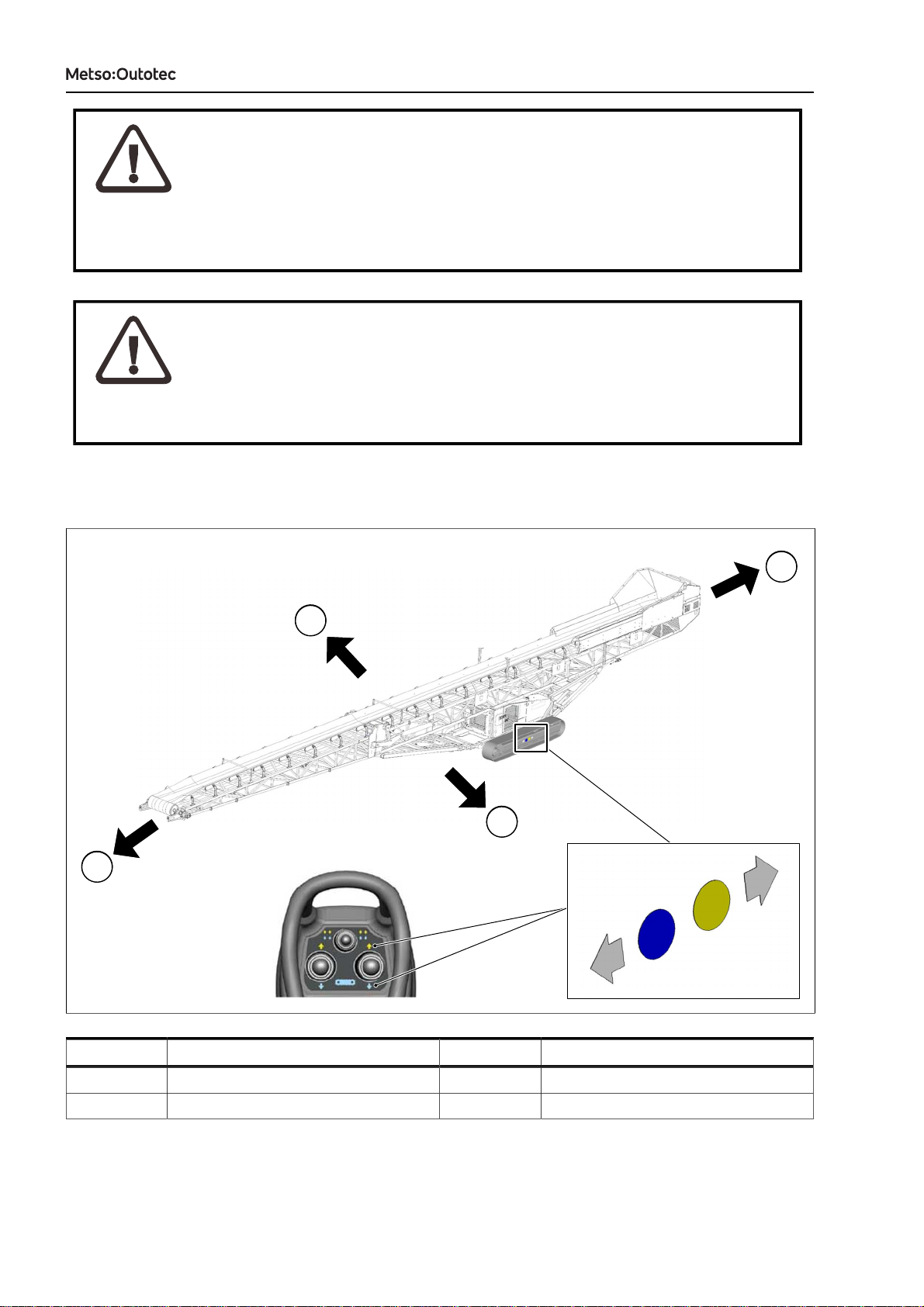
1.2. DRIVING DIRECTIONS
4
3
2
1
3
4
2
1
Callout Description Callout Description
1 Forward (yellow) 2 Backward (blue)
3 Right 4 Left
Figure 1: Nordtrack CT85(R) driving directions
DRIVING INSTRUCTIONS
DRIVING INSTRUCTIONS D100013368-EN
344 0 EN 2021-04-20
3
4
3
2
1
3
4
2
1
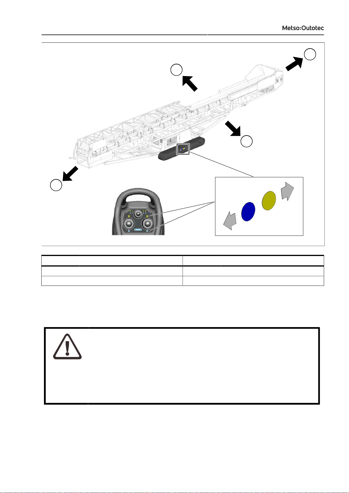
Callout Description Callout Description
1 Forward (yellow) 2 Backward (blue)
3 Right 4 Left
Figure 2: Nordtrack CT100(R) driving directions
1.3. EMERGENCY STOP LOCATIONS
DANGER!
GENERAL HAZARD
Will cause death or serious injury.
In a dangerous situation, stop the machine with the emergency stop button,
the key switch of the machine, or with the remote stop button (located on
either the drive control device, radio control device). Before starting the
machine, make sure that you know the location of the emergency stop
buttons.
DRIVING INSTRUCTIONS
4 D100013368-EN
344 0 EN 2021-04-20
DRIVING INSTRUCTIONS
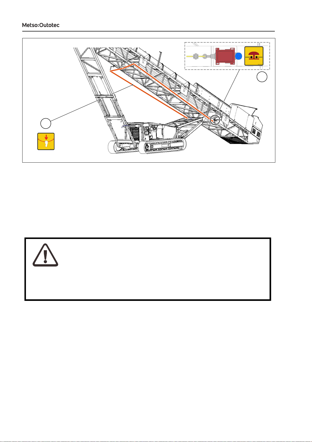
1
2
Figure 3: Nordtrack CT85(R) and Nordtrack CT100(R) emergency stop locations
To stop the machine quickly in an emergency, pull the yellow emergency pull-cord (1), which runs along both
left and right side of the machine’s center frame.
To restart the machine after an emergency stop, pull the blue emergency stop reset button (2), located on the
left side of the machine where the rear undercarriage joins the conveyor frame.
1.4. REMOTE STOP LOCATION
DANGER!
GENERAL HAZARD
Will cause death or serious injury.
In a dangerous situation, stop the machine with the emergency stop button,
the key switch of the machine, or with the remote stop button. Before starting
the machine, make that sure you know the location of the emergency stop
buttons.
DRIVING INSTRUCTIONS
DRIVING INSTRUCTIONS D100013368-EN
344 0 EN 2021-04-20
5
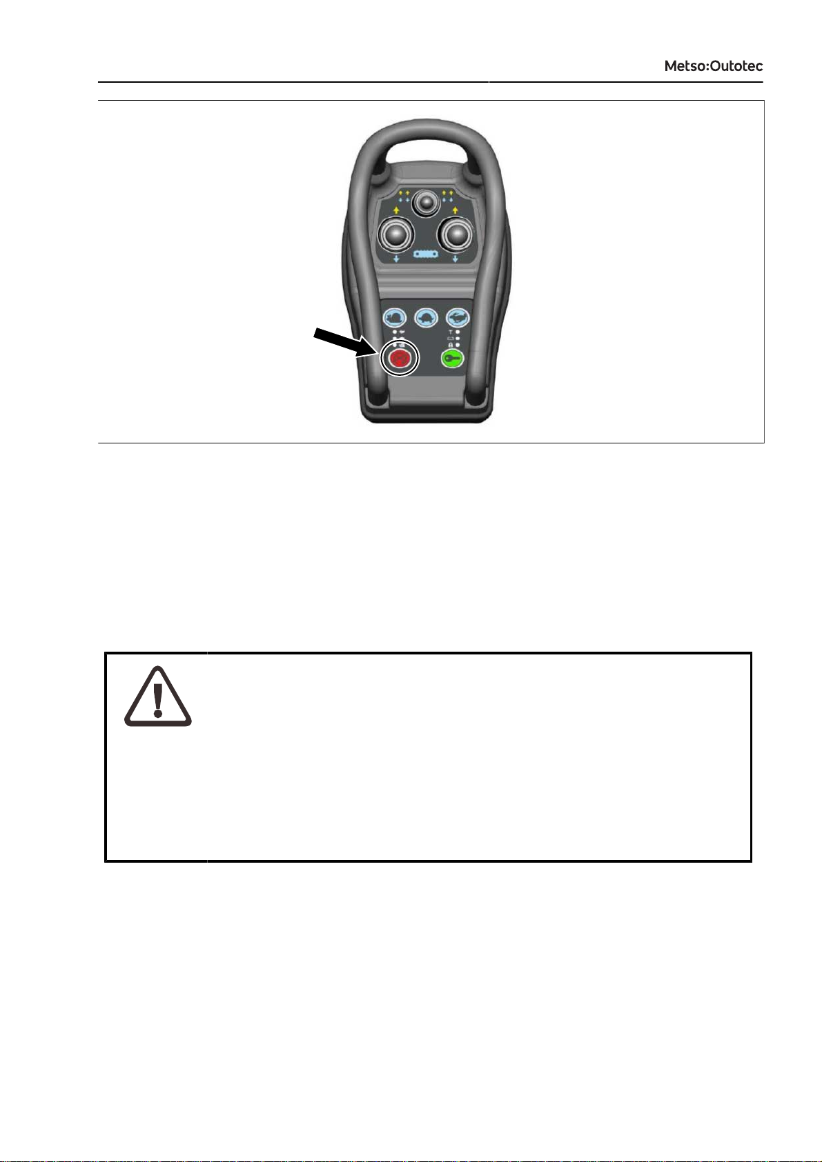
Figure 4: Location of remote stop button
The remote stop button on the remote control device, if fitted, is not an emergency stop but can be used for
stopping the machine.
1.5. DRIVE CONTROLS
1.5.1. REMOTE CONTROL DEVICE
WARNING!
UNEXPECTED MOVEMENT HAZARD
Unexpected movement can cause death or serious injury.
Make sure that the cable (if fitted) of the remote control device does not get
caught in the tracks or in any other moving part of the machine during driving.
The remote control device must be disconnected from the machine
immediately after driving and stored in a safe place when not in use.
Only lift and hold the remote control device by its handles. Do not pull the
device from the cable or drag or move it otherwise.
Sleep Mode ON/OFF: The remote control device enters a sleep mode after being inactive for more than
5 minutes. To exit the sleep mode: press the Green lock button (6), or press the Red stop button (7), or
activate one of the track toggles (1, 2, 3).
Power ON/OFF: Hold down the green Lock button (6) for 3 seconds.
DRIVING INSTRUCTIONS
6 D100013368-EN
344 0 EN 2021-04-20
DRIVING INSTRUCTIONS
5
1
5
2
5
6
5
7
3
5
4
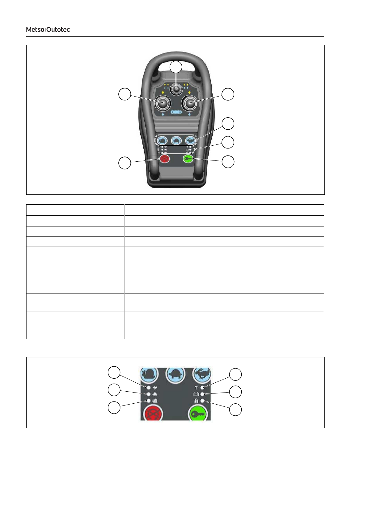
Callout Description
1 Left hand track forward/reverse
2 Right hand track forward/reverse
3 Left and right track together forward/reverse
4 Track driving speed (option)
Press one of the three buttons to set the track driving speed.
• Snail – Slow
• Tortoise – Medium
• Hare – Fast
5 Information LEDs that provide information about track driving speed
and the state of remote control device.
6 Lock/Unlock
Press this button to lock, unlock, or energize the remote control device.
7 Engine stop request
Figure 5: Remote control device
1
2
3
4
5
6
Figure 6: Overview of the LEDs of remote control device

DRIVING INSTRUCTIONS
DRIVING INSTRUCTIONS D100013368-EN
344 0 EN 2021-04-20
7
Callout LED Color Mode Description
1 Speed: Hare Green Steady Track driving speed set to
fastest.
2 Speed: Tortoise Green Steady Track driving speed set to
medium.
3 Speed: Snail Green Steady Track driving speed set to
slowest.
Green Steady Paired with machine and in
range.
Orange Flashing Pairing in progress4 RF status LED
Red Steady Not paired with machine or
out of range.
Flashing The battery of remote
control device is charging.
Green
Steady The battery of remote
control device is charged.
Orange Steady The battery charge is low.
5 Battery
Red Steady The battery is out of
charge.
Red Flashing The remote control device
is locked.
6 Lock/Unlock
Green Steady The remote control device
is unlocked.
1.6. PREPARING FOR DRIVING
NOTICE: Make sure the following:
• Make sure that you are familiar with the machine. Read the safety
instructions from the start of this manual.
• The process is set to STOP and it will not be started during transportation.
• The driving route is smooth enough.
• Differences in altitude or inclinations do not prevent driving.
• The lighting is appropriate at the site or near the machine.
• Make sure that the area is clear of obstructions and personnel. Especially,
take into account any low-hanging wires, trees, or roof bars.
• Inspect the path where the machine will be driven. Avoid track driving on
a steep slope. Make sure that there are no steep hills, valleys, bumps, or
holes on the path.
• The driving surface is not icy or slippery. If needed, sprinkle sand on the
surface.
• Inform all personnel about the track driving path.
• Consider the end point of the track driving path. The machine may need
to be positioned in a certain direction. If needed, make sure that there is
enough space to turn the machine around.
DRIVING INSTRUCTIONS
8 D100013368-EN
344 0 EN 2021-04-20
DRIVING INSTRUCTIONS
WARNING!
PERSONAL INJURY HAZARD
Exhaust gases are harmful, and when accumulated, can cause death or
serious injury.
If the track driving path includes enclosed space, such as a warehouse
or a shipping container, make sure that the enclosed space has sufficient
ventilation during track driving.
1. Visually inspect that there are no loose parts, and everything is secured in place.
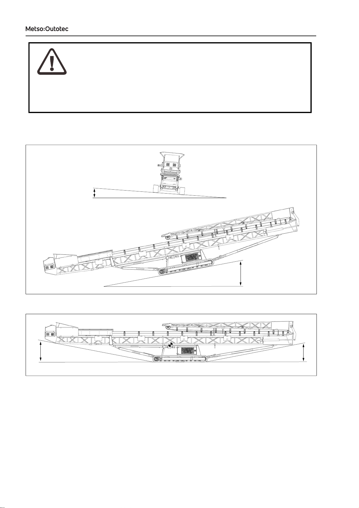
2. Check the inclinations, approach angle, and departure angle of the machine.
15
°
5
°
Figure 7: Maximum inclinations
11
°
11
°
Figure 8: Maximum approach and departure angle
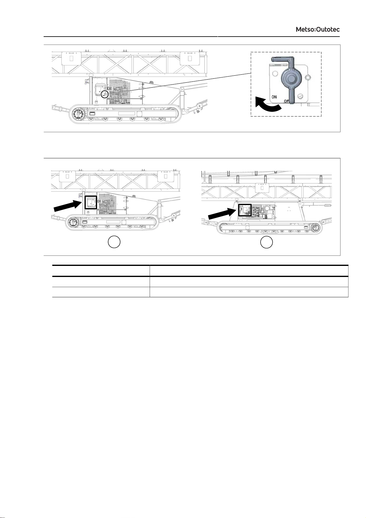
3. On the left-hand side of the machine, locate the main switch and turn it to ON position.
DRIVING INSTRUCTIONS
DRIVING INSTRUCTIONS D100013368-EN
344 0 EN 2021-04-20
9
Figure 9: Main switch
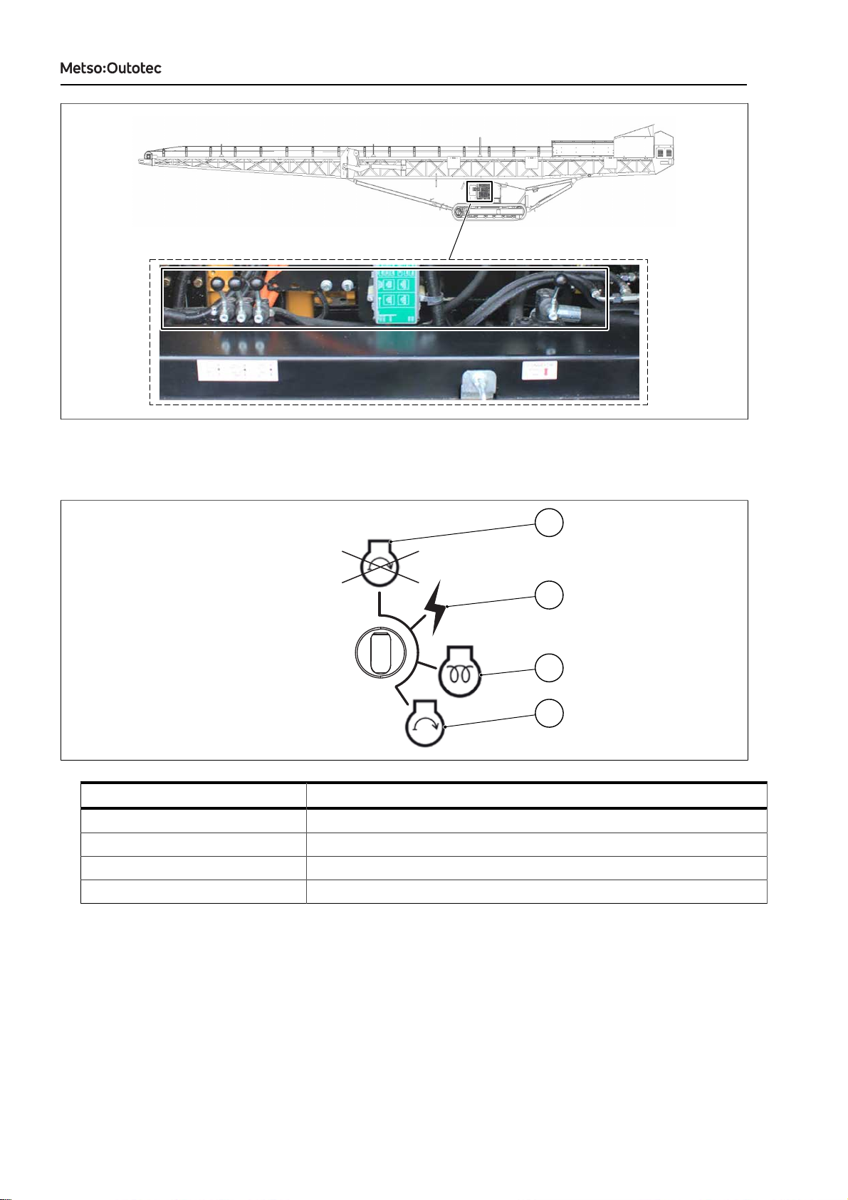
4. Locate the control panel. It is located within or next to the power unit of the machine.
1
2
Callout Description
1 Control panel location of Nordtrack CT85(R)
2 Control panel location of Nordtrack CT100(R)
Figure 10: Control panel location

DRIVING INSTRUCTIONS
10 D100013368-EN
344 0 EN 2021-04-20
DRIVING INSTRUCTIONS
9
12
16
15
14
13
1
10
1
11
5
6
7
8
4
18
17
2
1
1
3
Figure 11: Control panel (Tier 3 engines)

DRIVING INSTRUCTIONS
DRIVING INSTRUCTIONS D100013368-EN
344 0 EN 2021-04-20
11
Callout Description Callout Description
1 Power: This LED should be lit when
the key switch is turned to ON
position. If the LED is flashing, the
fuse that charges the remote control
device has blown.
2 Radio signal indicator light
• Green: Receiving valid radio
signal
• Red: Radio stop command
received
3 Track driving: The LED goes red
when the operator requests track
driving by performing the unlock
sequence on the remote control
device. The LED stays red while the
pre-track timer is counting down. The
timer is reset when a track switch is
toggled. The LED will go green when
the machine is ready for track driving.
4 Feeder valve ON/OFF: Not in use for
this model
5 Battery charging (warning): The LED
goes red when the alternator is not
charging the battery. The panel does
not shut down under this condition.
This LED is for warning only.
6 Oil pressure (warning): The LED goes
red when the sensor is detecting a
low engine oil pressure. The LED
starts blinking when it goes to its
shutdown condition, engine has been
running for 20 seconds, and the
switch has been closed for 2 seconds.
7 Oil temperature sensor: The LED
goes red when the sensor is detecting
a high engine water temperature. The
LED starts blinking when it goes to
its shutdown condition, engine has
been running for 20 seconds, and the
switch has been closed for 2 seconds.
8 Air filter/water in fuel: This LED is lit if
either the air filter pressure switch is
activated or the water in fuel sensor
(where fitted) activates. And it starts
blinking when it goes to its shutdown
condition, engine has been running
for 20 seconds, and switch has been
closed for 90 seconds.
9 Emergency stop: This LED will only
be lit if one or more of the emergency
stops have been pressed. This LED
will stay lit until the emergency stops
have been released.
10 Cranking engine: This LED lights red
during the pre-crank delay before
engine starts cranking.
11 Hydraulic oil level sensor: The LED
goes red when the sensor is detecting
a low hydraulic oil level. The LED
starts blinking when it goes to its
shutdown condition (no oil seen for 30
seconds).
12 Coolant level sensor: The LED goes
red when the sensor is detecting a
low coolant level. The LED starts
blinking when it goes to its shutdown
condition (no coolant seen for 30
seconds).
13 Key switch: OFF position 14 Key switch: Power ON position
15 Key switch: Engine pre-heat position 16 Key switch: Crank position
17 Total engine hours 18 Cabinet lock
DRIVING INSTRUCTIONS
12 D100013368-EN
344 0 EN 2021-04-20
DRIVING INSTRUCTIONS
11
12
14
13
1
2
3
4
5
6
7
8
9
10
A
B
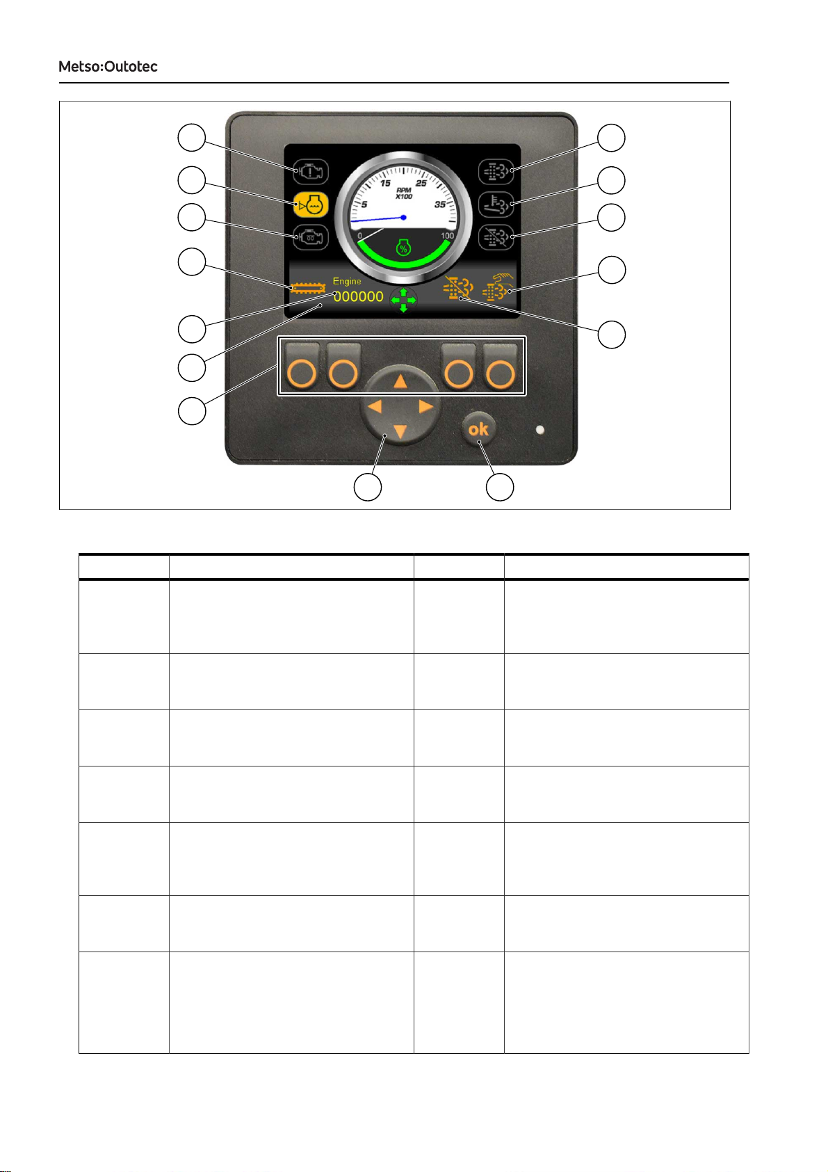
Figure 12: Control panel (Tier 4 engines)
Callout Description Callout Description
1 Engine fault warning: Illuminates
when an engine fault is detected.
2 Coolant level: Illuminates when
coolant level is too low, and flashes
when the engine shuts down as a
result of insufficient coolant.
3 Engine pre-heat: Illuminates when the
engine pre-heat is active during start-
up.
4 Track driving: Illuminates orange
when track driving is disabled, and
green when track driving is enabled.
5 Total engine hours 6 Diesel Particulate Filter (DPF):
illuminates when a DPF regeneration
is required.
7 DPF regeneration active: Illuminates
during DPF regeneration
8 DPF regeneration Inhibited:
Illuminates when the automatic DPF
regeneration is disabled.
9 Manual DPF regeneration: Press the
button (A) to force-start manual DPF
regeneration
10 Disable automatic DPF regeneration:
Press the button (B) to disable
or enable the automatic DPF
regeneration.
11 Control panel display 12 These 4 buttons are used for
selecting different page-dependent
options
13 Direction-pad is used for:
• Navigating through different
display pages (left and right)
• Controlling the engine RPM (up
and down)
14 OK button used for confirming a given
selection
DRIVING INSTRUCTIONS
DRIVING INSTRUCTIONS D100013368-EN
344 0 EN 2021-04-20
13
5. Make sure that the emergency stop buttons are not pressed, and also that the remote stop button is
not pressed down.
6. Proceed to the next section: “Starting the engine”.
1.6.1. STARTING THE ENGINE
WARNING!
EXPLOSION HAZARD
Can cause death or serious injury.
Do not use startup spray or similar to help the engine start, because it might
cause a destructive explosion in the induction manifold.
WARNING!
PERSONAL INJURY HAZARD
Can cause death or serious injury.
Before starting the machine, make sure that there are no persons in the area
whose safety may be endangered. Walk around the machine and make sure
that there is nobody on, by or below the machine. Warn everybody in the
vicinity before starting.
NOTICE: Wear personal protective equipment at all times. Make sure that no personnel
are on the machine.
1. Observe all safety warnings.
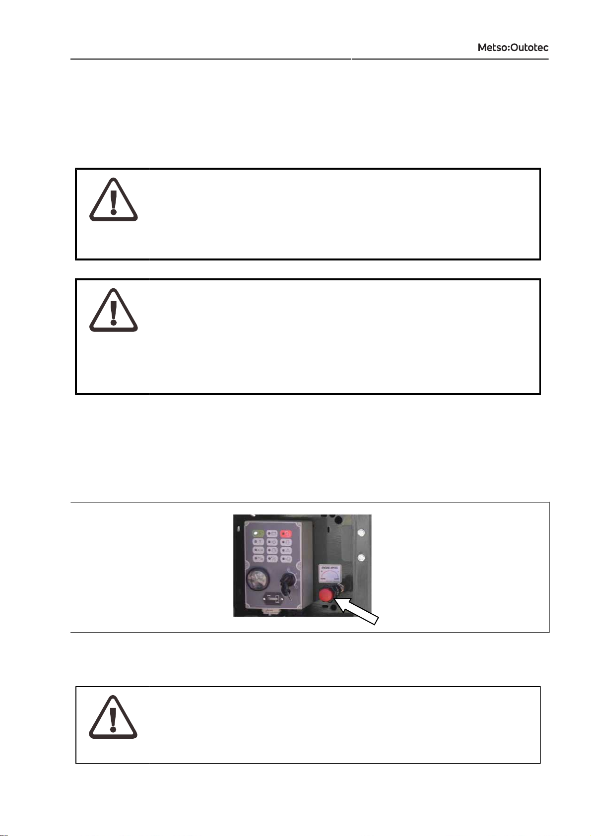
2. Set the Throttle knob to idle rpm (Tier 3 engines only).
Figure 13: Throttle knob, (Tier 3 engines only)
3. Check that all control levers are in neutral (OFF) position, and all emergency stops are released.
CAUTION!
PROPERTY DAMAGE HAZARD
Can cause moderate injury or property damage.
Make sure that all control levers are in the neutral (OFF) position.
DRIVING INSTRUCTIONS
14 D100013368-EN
344 0 EN 2021-04-20
DRIVING INSTRUCTIONS
Figure 14: Control levers in neutral (OFF) position
4. Insert the key into the ignition switch of main control panel.
5. Turn the key clockwise to the Power ON position (2).
1
2
3
4
Callout Description
1 OFF
2 Power ON
3 Engine pre-heat
4 Crank
Figure 15: Ignition key positions
6. Turn the key clockwise to the Engine pre-heat position (3). The Engine pre-heat lamp will illuminate.
Wait until this lamp goes out before continuing.
7. Turn the key clockwise further to the Crank position (4). You will hear an audible start alarm signal to
indicate that the machine is about to start.
8. Hold the key in the Crank position (4) for 10 seconds. During the 10 seconds, the alarm will continue
to sound.
9. Release the key immediately after the engine starts.
DRIVING INSTRUCTIONS
DRIVING INSTRUCTIONS D100013368-EN
344 0 EN 2021-04-20
15
10. Before operating the machine, allow the engine to run at idle for 5 minutes to allow the running
temperature to be reached.
11. Check around the engine compartment area for engine oil, fuel, coolant, or hydraulic fluid leaks.
12. If your machine has a Tier 4 engine, prevent DPF regeneration by pushing the Disable automatic DPF
regeneration button (B) on the control panel.
If needed, press the button (A) to force manual DPF regeneration.
A
B
Figure 16: DPF regeneration (Tier 4 engines)
WARNING!
FIRE HAZARD
Can cause moderate injury or property damage.
Prevent the DPF regeneration in situations when it might be possible that heat
from the exhaust pipe causes property damage or personal injuries.
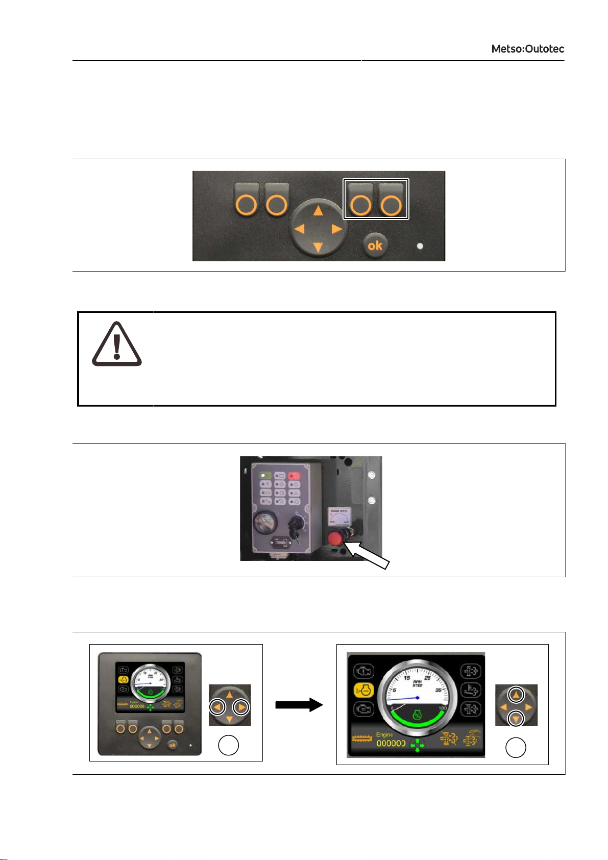
13. Adjust the engine rpm if needed. (Track driving can be done at any rpm.)
a. Tier 3 engines: Use the Throttle knob to control engine rpm.
Figure 17: Adjusting the engine rpm (Tier 3 engines)
b. Tier 4 engines: Go to the main page of control panel display. Use the Left and Right arrows (A) to
switch display pages, and the Up and Down arrows (B) to control the engine rpm.
A
B
Figure 18: Adjusting the engine rpm (Tier 4 engines)
DRIVING INSTRUCTIONS
16 D100013368-EN
344 0 EN 2021-04-20
DRIVING INSTRUCTIONS
NOTICE: The engine is programmed to auto-shutdown after 30 minutes of being idle.
This safety feature reduces the engine idle hours, which reduces emissions and
extends the engine and component lifetime.
When the engine is idling or running under 1800 rpm, a timer on the main page
of the display shows the seconds remaining until auto-shutdown. To stop the
auto-shutdown timer, increase the engine rpm.
The auto-shutdown will not occur in track driving mode.
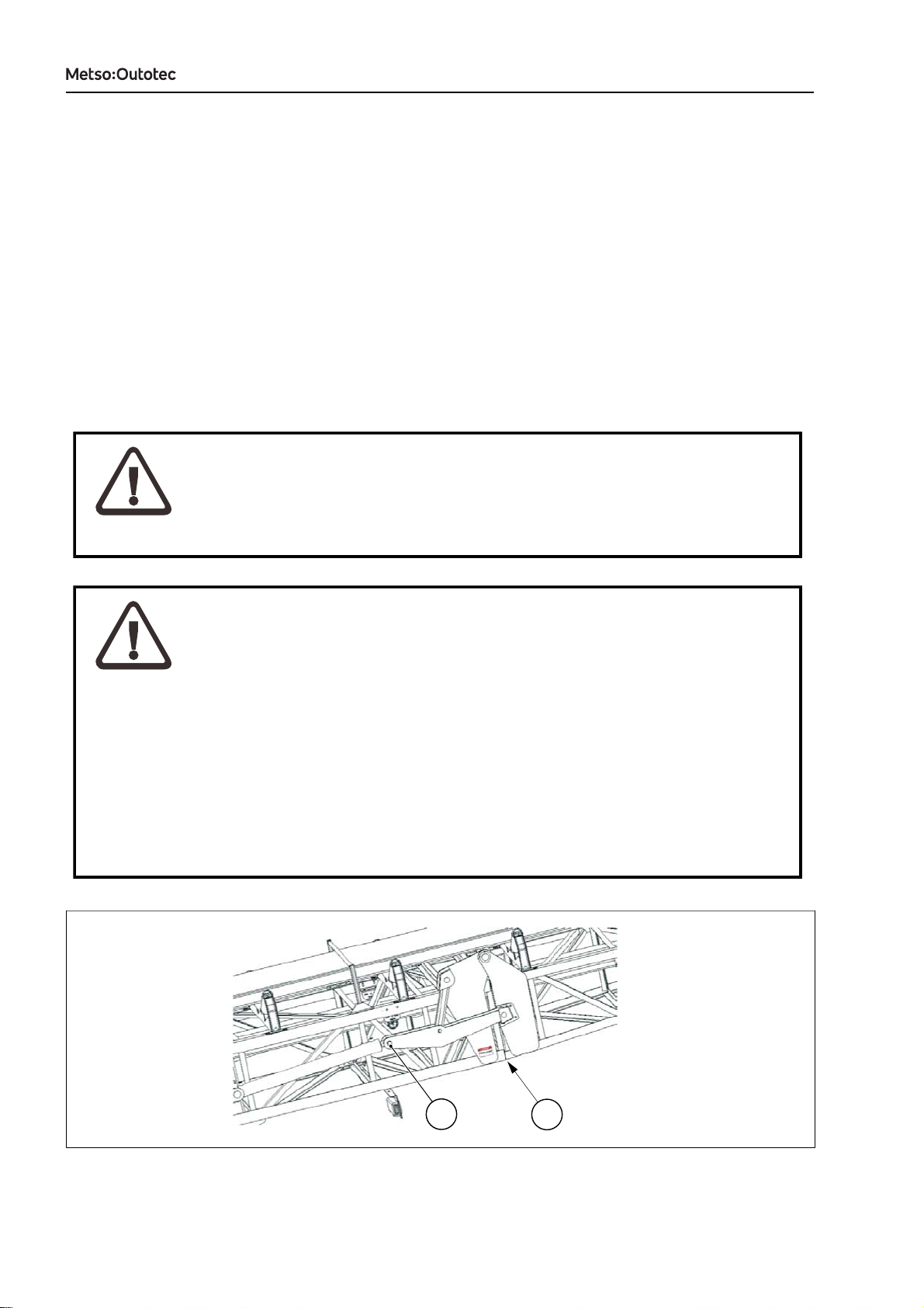
1.6.2. UNFOLDING THE CONVEYOR (CT85(R) ONLY)
To ensure proper weight balance during track driving of CT85(R) stackers, the conveyor must be unfolded
before track driving.
WARNING!
GENERAL HAZARD
Can cause death or serious injury.
Make sure that the machine unit stands on an even surface before operation.
WARNING!
PERSONAL INJURY HAZARD
Can cause death or serious injury.
• When unfolding a conveyor, pay attention to conveyor clearances and
possible obstacles.
• Make sure that there are no loose items on any part of the conveyor.
• Check the condition of the fold mechanism, especially check the cotter pin
connections (1). Do not proceed if any damages are found.
• Make sure that nobody is in the restricted area when conveyor is folded or
unfolded.
• As the conveyor unfolds, personnel need to stay well clear of the pinch
points (2).
2
1
This manual suits for next models
3
Table of contents
Other Metso Outotec Industrial Equipment manuals


Popular Industrial Equipment manuals by other brands


SCHUNK
SCHUNK NSE mini 90 Assembly and operating manual

TigerStop
TigerStop AutoLoader user manual

Textron
Textron GREENLEE SG4 instruction manual

MÄDLER
MÄDLER FS Mounting and operating instructions

Vaillant
Vaillant 010038384 Installation and maintenance instructions

SCHUNK
SCHUNK VERO-S NSE mikro 49-13 Translation of original operating manual


