Wachs TRAV-L-VAC 300 User manual

REV: 21
JAN. 2003
Part Number:
Revision No: 0
i
TRAV-L-VAC 300
TRANSPORTABLE
VACUUM SYSTEM
MODEL TLV 300
PIPE & VALVE
MAINTENANCE EQUIPMENT
Model TLV 300 Ser.No.
E.H. WACHS COMPANIES
100 Shepard St. Wheeling Il. 60090
Patent Pending
E.H. Wachs Company
600 Knightsbridge Pkwy., Lincolnshire, IL 60069
59-MAN-01


WACHS TRAV-L-VAC 300
3
TABLE OF CONTENTS
INTRODUCTION
I. Standard & optional features ................................................................................. 4
II. Specifications ........................................................................................................ 4
III. Safety ................................................................................................................... 5
IV. Installation procedures .......................................................................................... 6
SET UP & OPERATING PROCEDURES
I. Before departure to jobsite..................................................................................... 7
II. Trav-L-Vac set up procedure .................................................................................. 7
III. Trav-L-Vac operating procedure .......................................................................... 7-9
IV. Liquid debris removal .......................................................................................... 10
V. Solid debris removal ............................................................................................ 11
VI. Operating tips ...................................................................................................... 12
MAINTENANCE .......................................................................................................... 13-15
CHARTS AND GRAPHS ............................................................................................. 16-18
DRAWINGS AND PARTS LISTS ............................................................................... 19-23
ORDERING INFORMATION ............................................................................................ 24

WACHS TRAV-L-VAC 300
4
INTRODUCTION.
Wachs Trav-L-Vac Transportable Vacuum Systems are
designed for a wide variety of field applications from curb box,
valve box, catch basin and vault clean out, as well as the clean
up of sludge and industrial spills, to key hole excavation for
curb box installation or replacement.
Trav-L-Vac Systems are completely self contained, built on
a structural steel base including: engine, holding tank, blower,
filtration system and suction tube.
The TRAV-L-VAC 300, the smallest member of the TRAV-L-
VAC line, features strong lifting capability and the largest
capacity holding tank in its class.
The TRAV-L-VAC 300 handles solid and liquid debris safely
and quickly. Available "skid mount" for operation from pick up
truck beds or compact "trailer system" for towing to jobsites.
SECTION I STANDARD EQUIPMENT
SECTION II MACHINE SPECIFICATIONS
STANDARD FEATURES:
• Fabricated base of channeled steel and steel plate with fork lift
slots.
• Large capacity holding tank with manually activated dump gate
and 2" ( 50.8 mm) drain plug.
• 3-stage filtration system.
• Heavy-duty positive displacement blower with silencer.
• Vacuum relief valve.
• Gasoline drive.
• 2-1/2" (63.5 mm) diameter x 10' (3.0 m) flexible wire reinforced
rubber suction hose.
• 2" (50.8 mm) diameter x 6 1/2' (2.0 mm) steel suction tube with
handles.
• Quick disconnect cam lock couplings.
• High liquid level shut off switch.
• Hour meter & tachometer.
OPTIONAL FEATURES:
• Trailer package • Light package
• Suction tubes • Custom colors
POWER SOURCE
• 20 HP gasoline engine.
BLOWER
• Belt drive positive displacement rotary lobe impeller type with 14"
( 355.6 mm) Hg maximum capacity.
• 345 CFM ( 9.77 cmm) @ 3600 RPM with 14" ( 355.6 mm) Hg.
• 15,813 FPM (4,819.8 cmm) air velocity through 2" (50.8mm) diam-
eter inlet
FILTRATION
• Primary drum filter with 2" ( 50.8 mm) of polyethylene foam.
• Secondary filter of fine polyethylene foam.
• Final filter, 10 micron polyester cartridge.
• All filters are washable with water.
HOLDING TANK
• 12 cu. ft. (.34 cu. m) 90 liquid gal. ( 33.7 L.) actual holding capacity.
• 32" (812.8 mm) diameter
• Equipped with vacuum relief valve, high level liquid shut off switch,
and hinged dump gate.
• 2" (50.8 mm) drain plug
FINISH: Durable painted finish w/
plated fasteners throughout.
UNIT DIMENSIONS (LxWxH): 40"x 60"x 55"
(1,016 x 1,524 x 1,397mm)
WEIGHT: 950 lbs ( 430.9 kg.)
BATTERY
For shipping purposes the battery is left empty. Battery acid is shipped
separately allowing for the customer to fill the battery upon delivery.
ENGINE
The Trav-L-Vav 300 utilizes a Kohler 20 HP. twin cylinder, air cooled
gasoline engine. Electric key start with speed control.
The engine and vacuum system have been factory tested. Enclosed
within the TLV 300 manual is the appropriate engine manual, main-
tenance and repair information.
GAS TANK
Use only regular grade unleaded gasoline with an octane rating of 87
or higher.
• 6 gallon capacity
• Always keep gas cap vent in the full open position.
BLOWER:
A Roots Universal 45 RAI series. The blower has been properly
lubricated at the factory. Enclosed with the Trav-L-Vac manual is the
Roots Blower manual, refer to it for specifications, maintenance and
repair information.
FILTRATION SYSTEM:
A three stage system, accessed from top of holding tank, utilizing
toggle clamp to lock filters in place. Easy clean with mild soap and
water.
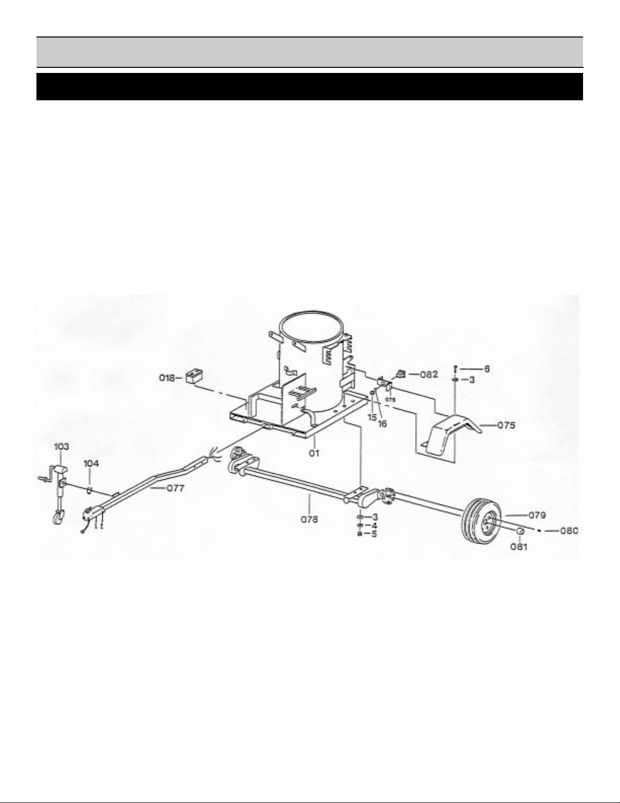
TRAILER BOLT ON KIT ( OPTIONAL ):
• 2,300 lbs. Trailer capacity
• Torsion axle
• 2" ball coupler or pintle
• 105" overall length
• 63" overall width

WACHS TRAV-L-VAC 300
5
SECTION III SAFETY INSTRUCTIONS
The E. H. Wachs Company takes great pride in manufacturing safe, quality products with user safety a
priority.The E.H. Wachs Company recommends that all users comply with the following safety rules and
instructions when operating our equipment. For your safety and the safety of others, read and understand
these safety recommendations and operating instructions before operating.
Read the Following thoroughly
before proceeding.
1. READ THE OPERATING MANUAL!! Reading the
setup and operating instructions prior to beginning the
setup procedures can save valuable time and help
prevent injury to operators or damage to machines.
2. INSPECT MACHINE & ACCESSORIES! Prior to
machine setup physically inspect the machine and it's
accessories. Look for worn tool slides, loose bolts or
nuts, lubricant leakage, excessive rust, etc. A properly
maintained machine can greatly decrease the chances
for injury.
3. ALWAYS READ PLACARDS & LABELS! All plac-
ards, labels and stickers must be clearly legible and in
good condition. Replacement labels can be purchased
from the manufacturer.
4. KEEP CLEAR OF VACUUM HOSE WHEN OPERATING
VACUUM! Keep hands, arms and fingers clear of vacuum
inlet. Always turn machine off before attempting any
adjustments, or changing wands.
WARNING
Impact resistant eye protection
must be worn while operating or
working near this tool.
CAUTION
Personal hearing protection is
recommended when operating or
working near this tool.
4. KEEP CLEAR OF ROTATING PARTS! Keep hands,
arms and fingers clear of all rotating or moving parts.
Always turn machine off before attempting any adjust-
ments requiring contact with the machine or it's acces-
sories.
5. SECURE LOOSE CLOTHING & JEWELRY! Loose fitting
clothing, jewelry; long, unbound hair can get caught in
the rotating parts on machines. By keeping these things
secure or removing them you can greatly reduce the
chance for injury.
6. KEEP WORK AREA CLEAR! Be sure to keep the
work area free of clutter and nonessential materials.
Only allow those personnel directly associated with the
work being performed to have access to the area if
possible.
• TAKE CARE IN TRANSPORTING VACUUM SYSTEM, ALWAYS
CHECK TRAILER HITCH, INSTALL SAFETY CHAINS, CHECK
BRAKE LIGHT-TURN SIGNAL OPERATION.
• DO NOT RUN ENGINE IN ENCLOSED AREA. EXHAUST
FUMES ARE DEADLY.
• DO NOT SMOKE WHEN FILLING FUEL TANK OR OPERAT-
ING VACUUM SYSTEM.
• DO NOT ALLOW GRASS, LEAVES, DIRT, RAGS OR COM-
BUSTIBLE MATERIALS TO ACCUMULATE AROUND ENGINE
AND MUFFLER.
• USE THIS TOOL FOR THE MANUFACTURERS IN-
TENDED PURPOSE ONLY.
• DO NOT FILL OR EMPTY VACUUM TANK WITHOUT
TRAILER CONNECTED TO TOWING VEHICLE OR
FRAME BOLTED TO TRAILER BED.
• SHUT SYSTEM DOWN BEFORE PERFORMING ANY
SERVICE TO THE EQUIPMENT.
• USE ALL APPROPRIATE AND APPLICABLE PERSONAL
SAFETY EQUIPMENTAS REQUIRED; SUCH AS, SAFETY
SHOES, HARD HAT, SAFETY GLASSES, HEARING
PROTECTION, ETC.


WACHS TRAV-L-VAC 300
7
SECTION IV
SET-UP
AND
OPERATING
PROCEDURES

WACHS TRAV-L-VAC 300
8
SECTION IV SET-UP AND OPERATION
TRAILER PACKAGE ASSEMBLY:
NOTE: REFER TO INSTALLATION DIAGRAM
1.Bolt fender braces (076) to dump gate sides by using 3/8-16 x 3/4
HHCS, 3/8 lock washers and 3/8-16 hex nuts.
2.Secure the fenders (075) to the fender braces by using 3/8-16 x 3/
4 HHCS, 3/8 lockwashers and 3/8-16 hex nuts. Align the holes in
the fender with the holes in the TLV frame (01).
3.Position the axle (078) under the frame with the torsion arms
trailing toward the dump gate. The axle is bolted to the fame
through the holes closest to the tongue side of the frame.
4.Join the fenders to the axle, through the frame, by using 1/2-13 x 4-
1/2 HHCS (6), 1/2 flat washers (3) 1/2 lock washers (4) and 1/2-
13 hex nuts (5). (Fig. 1)
12.Pull the green and brown wires up through the conduit directly
above the exit hole. The green and brown wires are for the RIGHT
tail light. (Fig. 2)
13.The yellow and brown wires are strung along the TLV frame
below the dump gate. The yellow and brown wires are for the
LEFT tail light. (Fig. 2)
14.Holes are predrilled in the frame to secure the wires using wire
clamps and #10 self drilling hex head screws.
15.Pull the yellow and brown wires up through the conduit and out
through the hole near the fender brace.
16.Remove the slack from the trailer wires and secure them to the
fender braces with the supplied adhesive wire clips.
17.Cut the trailer wires allowing for sufficient length to connect the
tail lights (082 & 083)
18.Strip the ends of the trailer wires 1/2" for proper connection.
19.Feed the trailer wires through the upper slots on the fender braces.
20.Push the stripped brown ends into the hole on the trailer lights
marked tail.
21.Push the stripped green and yellow ends into the hole on the
trailer lights marked stop.
22.Bolt the trailer lights to the fender braces using 1/4-20 hex nuts
and 1/4 lock washers.
23.Check that the lights are working properly.
24.Attach your license plate through the holes on the LEFT fender
brace. Apply the amber side markers on each side of the TLV 300
frame.
NOTE: Ensure that the axle is mounted perpendicular to
the direction of travel. A misaligned axle will decrease
tire life and will not tow satisfactorily.
5.Place the center caps (081) in the rim and mount the wheels
(079) on the axle using the lug nuts (080).
6.Pull the wire harness (084) wires through the hole at the back of
the tongue receiver. Do not remove the protective loom from the
wires.
7.Insert tongue (077) into the receivers. Be sure to pull the
excess wire with the tongue to avoid damage.
8.Line up the holes in the tongue with the holes in the receiver.
Secure the tongue in place with the supplied pull pins (090)
and keeper pins.
9.Attach the jack (103) to the tongue using the supplied snap ring
(104).
10.Pull the trailer wires through the holes under the TLV frame
until they come out the back corner, beneath the drain plug.
11.In addition to pulling the trailer wires through the holes, adhesive
wire clips (*106) are provided to keep the wiring secured to the
frame.
(Fig. 1)
(Fig. 2)

WACHS TRAV-L-VAC 300
9
SECTION IV SET-UP AND OPERATION
INSTALLATION DIAGRAM

WACHS TRAV-L-VAC 300
10
PRE-VACUUM CHECKLIST:
1. Insure all scheduled maintenance has been
properly performed. See maintenance section
in manual or refer to maintenance decal on
TLV.
2. Insure that the hitch assembly has been
properly attached to the towing vehicle.
3. Check trailer brake lights and turn signals.
4. Check TLV-300 fuel level.
5. Make certain battery is charged and ready to start TLV-
300 engine.
6. Make certain suction hose and suction tubes are stored
on board TLV-300
7. Check drive belt tension. Adjust as necessary. (Refer to
drive belt tensioning diagram in Charts and Graphs
Section)
TRAV-L-VAC 300 SET UP PROCEDURE:
1. Position TLV system near work area.
2. Connect coupling of suction hose to coupling on vacuum
inlet port. ( Figure 1)
3. Connect coupling on suction hose to coupling on
suction tube.
4. Once assembly of these components is complete, unit
is ready for operation.
TRAV-L-VAC OPERATING PROCEDURE:
1. Start engine and allow to idle several minutes to properly
warm up. (Figure 2)
2. Ensure vacuum diverter valve is closed to achieve proper
suction through the suction hose. If diverter valve is open
no suction will be present at the wand opening.
3. Bring engine RPM up to full running speed.
4. Insert suction tube into valve box and drop down until
contact is made with either water or debris. Continue to
SECTION IV SET-UP AND OPERATION
Figure 1
Figure 2

WACHS TRAV-L-VAC 300
11
SECTION IV SET-UP AND OPERATION
extract debris until valve box is empty or until holding
tank is full. (Fig. 3)
5. If the unit fills with liquid to its limit, the high liquid level
switch will automatically shut off the engine. Before
restarting unit, the holding tank must be drained. If this
is not done, unit will not start.
6. After the vacuum operation is over, run engine for several
minutes to clear out any water which may have reached
the blower.
7. Consult the manufacturer for special operating sugges-
tions concerning use in freezing weather.
TLV DUMPING PROCEDURES:
Liquids:
1. Shut down engine.
Figure 3
NOTE: If a clog occurs, shake suction hose. If clog
remains, open the vacuum diverter valve to remove
vacuum from suction hose. Disconnect the hose
from the TLV. Either use a ram to dislodge clogged
debris or reverse suction hose ends.
NOTE: If removing heavier or solid debris, the high
liquid level switch may not cause the unit to shut
down. Periodically inspect the holding tank to avoid
over filling.
Figure 4
2. Position vacuum system over designated dumping area.
3. If the material collected is primarily liquid, the holding
tank drain plug should be used to remove holding tank
contents.
4. Once liquid has drained, open dump gate and remove
any remaining debris. ( Fig. 4)
5. Clean primary filter prior to next use. Filter can be
cleaned with only water, however, mild soap and water
are recommended if possible. ( Fig. 5)
TLV DUMPING PROCEDURES (CONT.):
Solids:
Figure 5

WACHS TRAV-L-VAC 300
12
1. Shut down engine.
2. Position vacuum system over designated dumping area.
3. If the material collected is primarily solid, first open the
holding tank drain plug to allow any trapped liquids to
escape. open the holding tank dump gate. (Fig 6)
4. It may be necessary to remove any remaining debris from
the holding tank manually.
5. Clean primary filter prior to next use. Filter can be cleaned
with only water, however, mild soap and water are recom-
mended if possible. ( Fig. 7)
OPERATING TIPS
1. While excavating water, always be sure to submerge the
suction tube completely.
2. If debris is packed in the bottom of the valve box, rotate
the suction tube assembly back and forth to break up
debris.
3. For solid debris, pouring water into the valve box greatly
speeds up debris removal.
4. If suction tube on the TLV 300 becomes clogged, use a
rod with a smaller diameter than the inside of tube to as-
sist in blockage removal.
5. For optimal efficiency, flush out suction tubes and suction
hoses prior to storage.
6. Properly performing all scheduled operators maintenance
at the designated times will insure continued peak perfor-
mance and increase the longevity of the TLV 300 unit.
SECTION IV SET-UP AND OPERATION
Fig. 6
Fig. 7

WACHS TRAV-L-VAC 300
13
SECTION V
MAINTENANCE

WACHS TRAV-L-VAC 300
14
BLOWER MAINTENANCE SCHEDULE
WEEKLY
CHECK OIL LEVEL:
Stop blower. Wait 5 minutes. Remove oil breather and
oil level plug. Add oil until oil runs out level holes. Re-
place breather and level plugs.
GREASE BEARINGS:
Grease drive end bearings with NLGI grade 2 EP grease
in a pressure gun. Force into housing through grease
fittings until clean grease emerges from relief fittings.
Wipe clean all grease from around relief fittings to pre-
vent spraying onto drive belts.
EVERY 1,000 HOURS
CHANGE OIL.
NOTES
Change oil after initial 100 hours.
Recommended oil: Mobil DTE BB, Amoco 220, Texaco
R&O 220, or equivalent .
FILTER MAINTENANCE SCHEDULE
DAILY
Clean primary filter.
WEEKLY
Clean pre-filter
NOTES
Frequency of cleaning will increase under severe oper-
ating conditions.
All filters are washable with mild detergent and water.
Damaged filters must be replaced to prevent debris from
reaching blower.
MAINTENANCE
ENGINE MAINTENANCE SCHEDULE
DAILY
Check oil level.
Replenish fuel intake supply ( Unleaded fuel ).
Clean air intake screen.
Check tightness of air cleaner cover.
EVERY 25 HOURS
Service pre-cleaner.
EVERY 100 HOURS
Service paper element.
Remove shrouds, clean cooling fins, and external sur-
faces.
Check battery electrolyte level.
Change oil.
EVERY 200 HOURS
Check spark plug condition and gap, change oil filter.
NOTES
Change oil after first 5 hours.
BLOWER MAINTENANCE DIAGRAM
OIL GRADE DIAGRAM
FILTER MAINTENANCE DIAGRAM

WACHS TRAV-L-VAC 300
15
GENERAL MAINTENANCE SCHEDULE
DAILY
Check suction hoses for any abrasions, holes, kinks or
damaged connectors. Replace as needed.
Verify that all dump gate and filter lid camps are se-
cured tight. Adjust if necessary.
Clean any debris from dump door seal.
Verify that all trailer and/or accessory lights are func-
tioning properly. Repair or replace as needed.
WEEKLY
Clean holding tank from excessive debris build-up.
Check lug nuts and fasteners for tightness. Tighten as
necessary.
MONTHLY
Check blower drive belts for proper tension, frayed or
cracked condition. Adjust or replace as needed.
Check for loose piping, fittings, and connectors. Tighten
as needed.
Check tire pressure. Fill as necessary.
TO ADJUST "V" BELT
TENSION ROTATE THE
TENSIONING SHAFT (# 012)
TO THE RIGHT OR LEFT TO
TIGHTEN OR LOOSEN DE-
PENDING ON CURRENT "V"
BELT TENSION. oNCE
PROPER TENSION HAS BEEN
ATTAINED, LOCK SHAFT IN
PLACE BY TIGHTENING 3/4"
HEX NUT ON SHAFT
FOR DESCRIPTION OF OTHER REFERENCED
ITEMS IN DIAGRAM REFER TO MACHINE BILL OF
MATERIAL

WACHS TRAV-L-VAC 300
16
SECTION V
MISCELLANEOUS
CHARTS
AND
GRAPHS

WACHS TRAV-L-VAC 300
17
TRAV-L-VAC 300 ACOUSTIC EVALUATION
SOUND DECIBLE LEVEL DIAGRAM @ 10 FT

WACHS TRAV-L-VAC 300
18
TRAV-L-VAC 300PERFORMANCE CHARTS

WACHS TRAV-L-VAC 300
19
BILL OF MATERIAL

WACHS TRAV-L-VAC 300
20
056 59-079-00 2 HOSE CLAMP 1/2"
*057 62-091-00 1 SHUT DOWN DECAL
*058 59-116-00 2 TLV 300 DECAL
*059 59-086-00 1 MAINTENANCE DECAL
*060 59-088-00 1 WATER LEVEL DECAL
*063 67-108-00 1 S/N PLATE
*064 67-110-00 1 OPERATING LABEL
*065 67-116-00 1 GAS LABEL
*066 67-117-00 1 SAFETY LABEL
*067 62-091-00 1 SHUT DOWN DECAL
*068 59-117-00 1 OPEN MACHINE LABEL
*069 59-118-00 1 TLV-300 CRATE
*070 59-098-00 1 LABEL, EAR PROTECTION
*071 59-099-00 1 EYE PROTECTION LABEL
073 59-102-00 2 DUMP GATE HINGE
074 59-103-00 2 FILTER LID HINGE
075 59-010-00 2 FENDER
076 59-013-00 2 FENDER BRACE
077 59-022-00 1 TONGUE
078 59-075-00 1 AXLE
079 59-080-00 2 WHEELS
080 59-085-00 10 WHEEL NUTS
081 59-090-00 2 CENTER CAP
082 59-095-00 1 TRAILER LIGHT LH
083 59-100-00 1 TRAILER LIGHT RH
084 59-105-00 1 TRAILER WIRE HARNESS
*085 59-110-00 2 "S" HOOKS
*086 59-115-00 2 TONGUE GROMMET
*087 59-082-00 15' CABLE WRAP
*088 59-084-00 2 NO STEP STICKER
*089 59-089-00 1 TRAILER VIN PLATE
090 59-096-00 2 RECIEVER PULL PIN
*091 59-097-00 2 AMBER REFLECTOR
092 59-120-00 1 STROBE LIGHT
093 59-121-00 1 STROBE SWITCH
094 59-122-00 1 ACCESSORY OUTLET
095 62-083-00 1 ELBOW, 90° x 2-1/2"
096 59-003-00 1 DUMP GATE
097 59-004-00 1 FILTER LID
098 59-025-00 1 WAND DOOR
099 59-021-00 1 GUARD, TOP
100 59-027-00 1 GUARD, SIDE
101 59-006-00 1 FILTER DRUM PLATE
*102 59-107-00 2 HOSE CLAMPS
103 59-108-00 1 RETRACTABLE JACK
104 59-109-00 1 SNAP RING
*105 59-112-00 10' TUBING LOOM
*106 59-113-00 5 WIRE CLIPS, ADHESIVE
FASTENERS
*1 90-091-30 4 1/2-13 x 3" HHCS
*2 4 BLOWER WASHERS
3 90-095-52 16 1/2" FLAT WASHERS
4 90-095-55 10 1/2" LOCK WASHERS
5 90-095-01 10 1/2-13 HEX NUTS
6 90-091-45 6 1/2-13 x 4-1/2" HHCS
*7 90-071-20 6 3/8-16 x 2" HHCS
TRAV-L-VAC 300 BILL OF MATERIAL
PART NO. 59-000-01 & 59-401-01
REF. PART NO. QTY. DESCRIPTION
01 59-300-01 1 TLV FRAME
02 59-302-01 1 BLOWER W/ SILENCER
03 59-033-01 1 ENGINE
*04 59-034-00 1 MUFFLER
05 59-035-00 1 TACH / HOURMETER
06 59-036-00 1 FUEL TANK
07 59-037-00 3 V-BELT SHEAVE
08 59-038-01 1 BUSHING, V-BELT
09 59-039-00 1 BUSHING, V-BELT
010 59-040-00 2 V-BELT
011 59-041-00 1 BELT, TENSIONER
012 59-042-00 1 TENSIONER SHAFT
013 59-043-00 1 IDLER BUSHING
014 59-044-00 2 NYLON WASHER
015 59-045-00 2 NYLON WASHER
017 62-095-00 1 RAIN CAP
018 14-136-00 1 BATTERY
019 59-047-00 1 SWITCH, LIQUID LEVEL
*020 59-048-00 12' LID, SEAL
*021 59-049-00 1 DRAIN PLUG
*022 59-050-00 4 1-1/2" SQ. CAP
*023 59-051-00 6 1" CAP
*024 59-052-00 2 THREADED ROD
025 62-070-00 1 END CAP
026 59-053-00 2 FILTER STRAP
027 59-054-00 2 STRAP, VACUUM HOSE
028 59-055-00 1 SILENCER STRAP
030 62-054-00 1 FILTER
031 62-055-00 1 POLYURETHANE FILTER
032 62-801-00 1 POLYURETHANE FILTER
033 59-057-00 2 2-1/2" COMB. NIPPLE
*034 59-058-00 1 DUST CAP
*035 59-059-00 1 MALE COUPLING
*036 59-060-00 1 TERMINAL COVER
*037 59-061-00 1 2" BALL VALVE
*038 59-062-00 1 TEE
039 59-063-00 4' HOSE VACUUM
041 59-056-00 1 DUMP SEAL
*042 59-066-00 1 CONNECTOR, BULLET
*043 59-067-00 1 CONNECTOR, BULLET
*044 59-068-00 5 CONDUIT 1/2" PLASTIC
*045 59-069-00 2 CONNECTOR, NYLON
*046 59-070-00 5 MOUNTING, BRACKET
047 59-404-08 1 7/8" x 6-1/2' WAND
59-404-12 1 1-1/4" x 6-1/2' WAND
59-404-15 1 1-1/2" x 6-1/2' WAND
59-119-20 1 2" x 6-1/2' WAND
048 59-026-08 2 7/8" WAND INSERT
59-026-12 2 1-1/4" WAND INSERT
59-026-15 2 1-1/2" WAND INSERT
59-026-20 2 2" WAND INSERT
*049 59-071-00 1 MUFFLER GUARD
*050 59-072-00 1 EXHAUST DEFLECTOR
*051 59-073-00 18" CHAIN
*052 59-074-00 4 "S" HOOKS
59-074-01 2 "S" HOOKS
053 59-076-00 20 SELF TAP SCREWS #10
055 59-078-00 4' 1/4" FUEL LINE
*= NOT SHOWN
This manual suits for next models
1
Table of contents
Other Wachs Industrial Equipment manuals
Popular Industrial Equipment manuals by other brands

Marley
Marley Air 4.0 Operating & assembly instructions

LGL
LGL ECO POWER 2 instruction manual

Behncke
Behncke EWT 60-20 Installation instruction

Allwin21
Allwin21 GaSonics AURA 1000 Operator's manual

Siemens
Siemens SIMOGEAR 2730 Mounting and operating instructions

OZGENC MAKINA
OZGENC MAKINA SL 500 Operator's manual