Metso Nordtrack J127 User manual
Nordtrack J127
'RF1R'20717-EN5HYLVLRQ1
ಘ2ULJLQDOLQVWUXFWLRQV
DRIVING ,16758&7,21S
For more information and
language versions, see:
metso.com/driving
This document is proprietary to Metso Corporation and its affiliated companies (“Metso”). This document is intended for the use of Metso's customers only for the purposes of the
agreement under which the document is submitted and no ownership rights are hereby transferred. No part of the document shall be used, reproduced, translated, converted,
adapted, stored in a retrieval system, communicated or transmitted by any means, for any commercial purpose, including without limitation, sale, resale, licence, rental or lease,
without the prior express written consent of Metso.
Customer understands and accepts that the information in this document is subject to any change without notice. It is the customer's responsibility to determine whether there have
been any such updates or amendments.
The document has been prepared to be used by professional and properly trained personnel, and the customer assumes full responsibility when using it. Despite the fact that every
effort has been made to ensure that the information in this document is accurate Metso does not make any representations, warranties or guarantees, express or implied, as to the
accuracy or completeness of the document. In case of any discrepancies between different language versions English version shall prevail. Metso shall not be liable in contract, tort
or in any other manner whatsoever to any person for any loss, damage, injury, liability, cost or expense of any nature, including without limitation incidental, special, direct or
consequential damages arising out of or in connection with the use of the document. Metso's liability for any errors in the document is limited to the documentary correction of errors.
Metso logo is a registered trademark of Metso Corporation.
Other product names mentioned in this document may be trademarks of their respective companies, and they are mentioned for identification purposes only.
Copyright © Metso 2023. All rights reserved.
Metso
Address: PO Box 1220
FI-00101, Helsinki, Finland
Telephone: +358 20 484 100
Internet: www.metso.com
Status: Valid from product update:
R006
Original size:
A4
Customer: Project Phase: Site No:
Project Name: Customer Document ID:
Replaced by: Replaces: Language:
EN
Document Title:
Driving instructions
Nordtrack J127
Equipment No: Item No:
Original instructions Translation of the original instructions
Language: EN
Nordtrack J127 Driving instructions
2 (30) Copyright © Metso 2023. All rights reserved.
Project ID: Plant Code: Plant Unit Code: Document Type: Running No: Revision:
1
Metso Document ID:
D100020717

Contents
1.1 Driving instructions.............................................................................................................................. 4
1.1.1 Safety.....................................................................................................................................4
1.1.2 Driving directions................................................................................................................... 5
1.1.3 Emergency stop locations......................................................................................................6
1.1.4 Remote stop location............................................................................................................. 6
1.1.5 Drive controls.........................................................................................................................7
1.1.5.1 Remote control device............................................................................................. 7
1.1.6 Preparing for driving...............................................................................................................8
1.1.6.1 Starting the engine.................................................................................................11
1.1.6.1.1 Adjusting the engine speed......................................................................14
1.1.6.1.2 Monitoring engine information..................................................................15
1.1.6.1.3 Preventing and initiating DPF generation.................................................18
1.1.6.2 Connecting the remote control device (wireless connection).................................19
1.1.6.3 Connecting the remote control device (wired connection)..................................... 19
1.1.6.4 Unlocking the remote control device......................................................................21
1.1.7 Driving..................................................................................................................................22
1.1.8 Stopping the engine.............................................................................................................24
1.1.9 Troubleshooting................................................................................................................... 25
1.1.9.1 Pairing the remote control device to the machine..................................................26
Nordtrack J127 Driving instructions
Copyright © Metso 2023. All rights reserved. 3 (30)
Project ID: Plant Code: Plant Unit Code: Document Type: Running No: Revision:
1
Metso Document ID:
D100020717
1.1 Driving instructions
These driving instructions are valid for Nordtrack J127 machines. The purpose of these instructions is to
enable safe moving of the machine during transportation.
NOTE: Do not use the machine for screening or crushing solely based on these instructions. The
actual instruction manual for the machine is delivered separately.
NOTE: In these driving instructions, it is assumed that the machine is in the transport position. If
needed, see the actual instruction manual of the machine for information on how to prepare the
machine for transportation.
1.1.1 Safety
Because of the size and weight of the machine, pay special attention when moving the machine. It is highly
recommended that a banksman is used when the machine is moved.
DANGER
GENERAL HAZARD
Will cause death or serious injury.
Read the safety section before working with the unit. Only competent and trained personnel are
allowed to work with the unit.
WARNING
PERSONAL INJURY HAZARD
Can cause death or serious injury.
Before starting and during track driving the machine, make sure that there are no persons in the
area whose safety may be endangered. Establish a buffer zone of at least 4.5 m (15 feet) around
the machine. Walk around the machine and make sure that there is nobody on, by or below the
machine. Warn everybody in the vicinity before starting.
WARNING
CRUSHING HAZARD
Can cause death or serious injury.
Do not drive the machine in locations where there is a risk of squeezing. Always drive the machine
from a safe distance. If possible, drive the machine from either end of the machine.
Nordtrack J127 Driving instructions
4 (30) Copyright © Metso 2023. All rights reserved.
Project ID: Plant Code: Plant Unit Code: Document Type: Running No: Revision:
1
Metso Document ID:
D100020717
WARNING
UNEXPECTED MOVEMENT HAZARD
Can cause death or serious injury.
Be extremely cautious when driving in cold temperatures (below 0°C, 32°F). The response time of
the controls might be longer than usual due to stiff hydraulic oil.
WARNING
COLLISION HAZARD
Can cause death or serious injury.
Always drive the machine from a safe distance. Pay attention to the machine dimensions to avoid
power lines, bridges, branches and other obstacles.
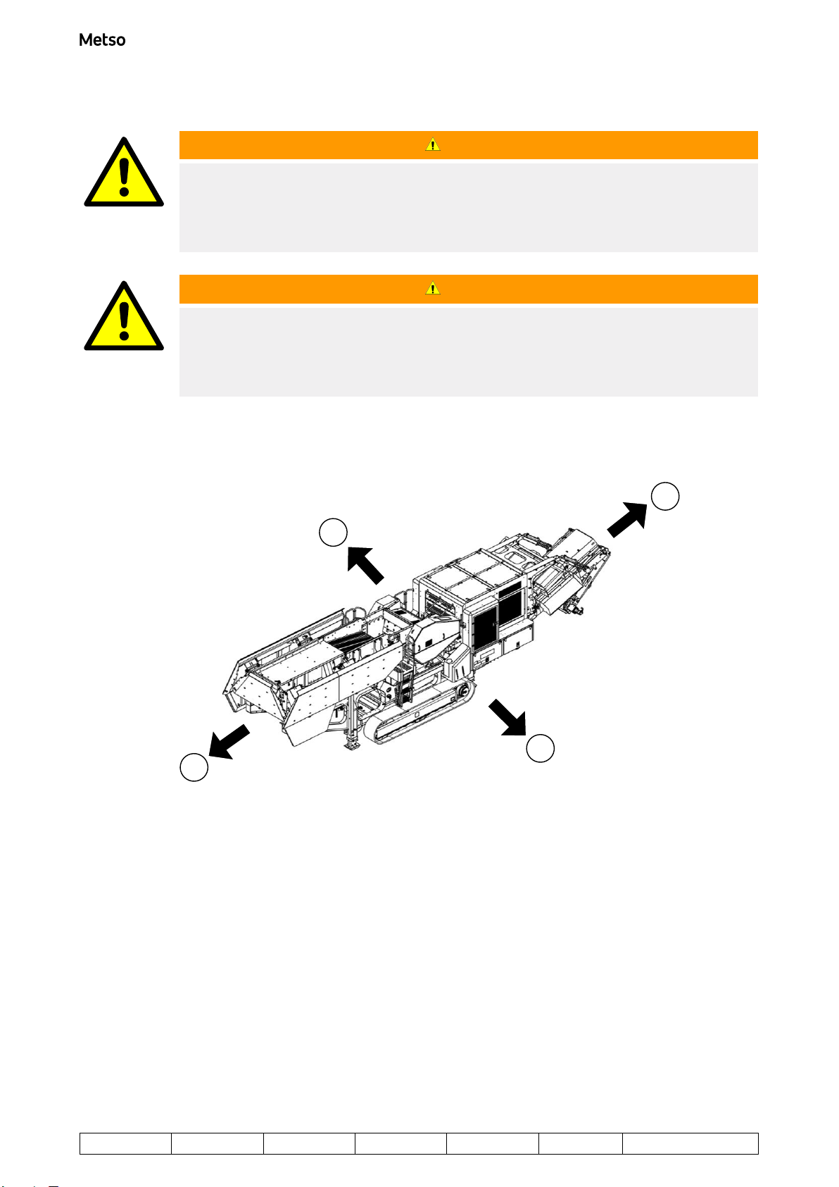
1.1.2 Driving directions
4
3
2
1
1. Forward 3. Left
2. Backward 4. Right
Nordtrack J127 Driving instructions
Copyright © Metso 2023. All rights reserved. 5 (30)
Project ID: Plant Code: Plant Unit Code: Document Type: Running No: Revision:
1
Metso Document ID:
D100020717
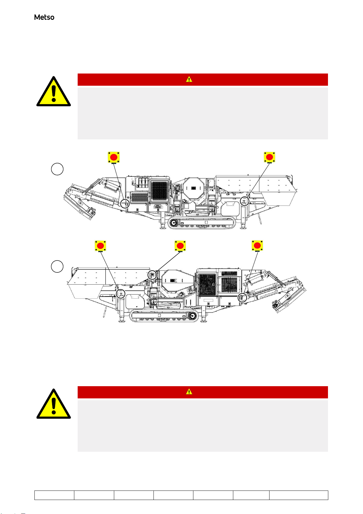
1.1.3 Emergency stop locations
DANGER
GENERAL HAZARD
Will cause death or serious injury.
In a dangerous situation, stop the machine with the emergency stop button, the key switch of the
machine, or with the remote stop button (located on either the drive control device or the radio
control device). Before starting the machine, make sure you know the location of the emergency
stop buttons.
1
2
Figure 1. Locations of emergency stop buttons
1. On the left side of the machine 2. On the right side of the machine
1.1.4 Remote stop location
DANGER
GENERAL HAZARD
Will cause death or serious injury.
In a dangerous situation, stop the machine with the emergency stop button, the key switch of the
machine, or with the remote stop button (located on either the drive control device or the radio
control device). Before starting the machine, make sure you know the location of the emergency
stop buttons.
Nordtrack J127 Driving instructions
6 (30) Copyright © Metso 2023. All rights reserved.
Project ID: Plant Code: Plant Unit Code: Document Type: Running No: Revision:
1
Metso Document ID:
D100020717
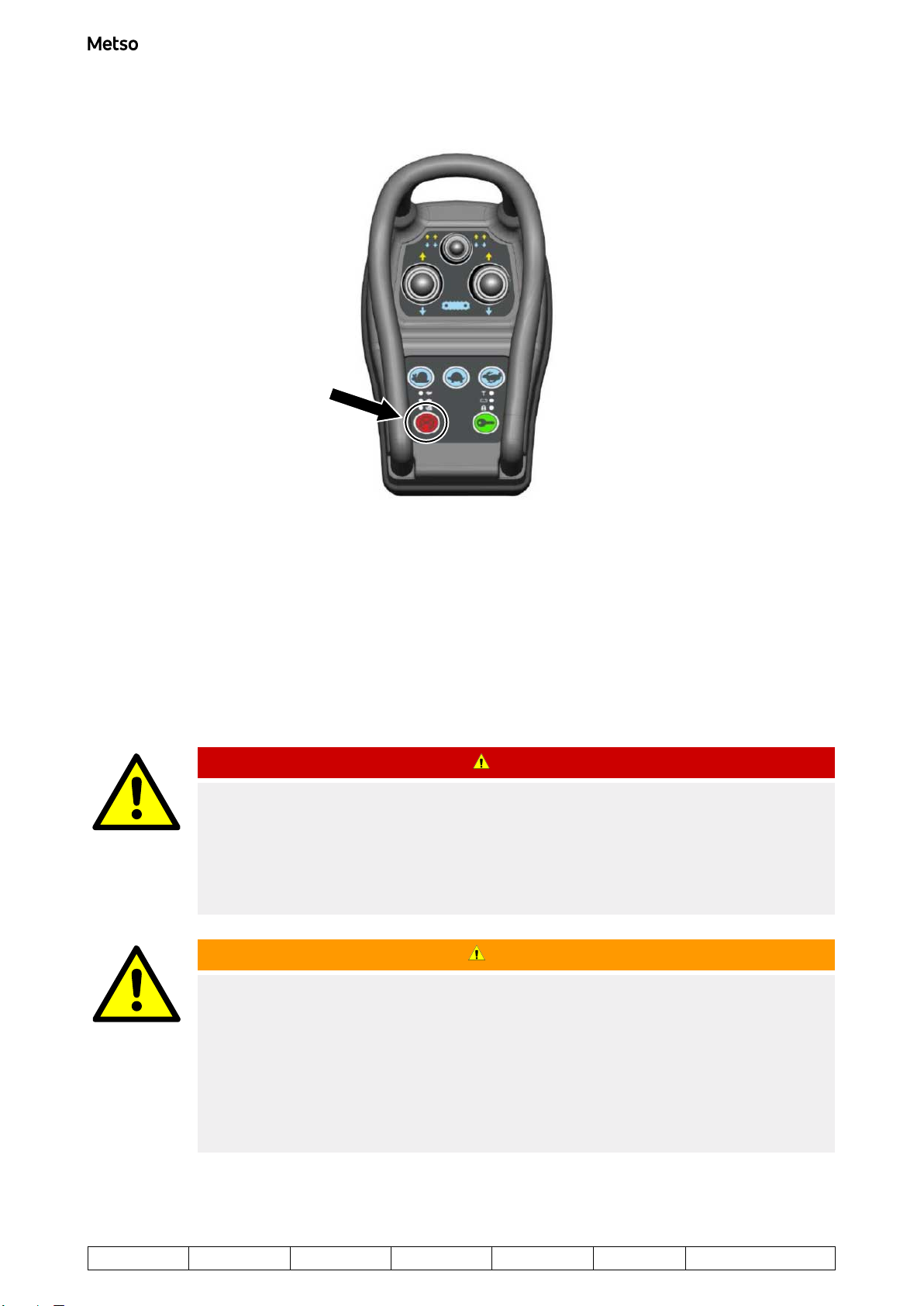
Figure 2. Location of remote stop button
The remote stop button on the remote control device, if fitted, is not an emergency stop but can be used to
stop the machine.
1.1.5 Drive controls
1.1.5.1 Remote control device
DANGER
GENERAL HAZARD
Will cause death or serious injury.
In a dangerous situation, stop the machine with the emergency stop button, the key switch of the
machine, or with the remote stop button (located on either the drive control device or the radio
control device). Before starting the machine, make sure you know the location of the emergency
stop buttons.
WARNING
UNEXPECTED MOVEMENT HAZARD
Can cause death or serious injury.
Make sure the cable of the drive control device does not get caught in the tracks or in any other
moving part of the machine during driving.
You must disconnect the drive control device from the unit immediately after driving and store it in a
safe place when not in use.
Only lift and hold the drive control device by its handles. Do not pull the drive control device from the
cable.
Nordtrack J127 Driving instructions
Copyright © Metso 2023. All rights reserved. 7 (30)
Project ID: Plant Code: Plant Unit Code: Document Type: Running No: Revision:
1
Metso Document ID:
D100020717

1
23
4
5
6
8
7
Figure 3. Remote control device
1. Left track and right track together forward/
reverse
5. Lock status LED
• Flashing green indicates that the radio control
device is locked
• Non flashing green indicates that the radio
control device is unlocked
• Flashing red indicates that the radio control
device is charging
2. Right hand track forward/reverse 6. Lock/Unlock button
3. Left hand track forward/reverse 7. Engine stop request button: pressing button will
send a signal to stop the engine (when paired and
in range)
4. Track speed setting (Slow/Intermediate/Fast) 8. RF status LED
• Green when paired with machine and in range
• Red when unpaired with machine or out of
range
1.1.6 Preparing for driving
1. On the left-hand side of the machine, locate the main switch (1) and turn it to ON position.
Nordtrack J127 Driving instructions
8 (30) Copyright © Metso 2023. All rights reserved.
Project ID: Plant Code: Plant Unit Code: Document Type: Running No: Revision:
1
Metso Document ID:
D100020717
1
Figure 4. Main switch
2. Visually inspect that there are no loose parts, and everything is secured in place.
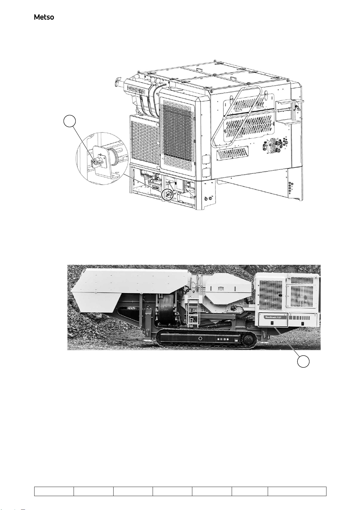
3. Locate the control panel. It is located in the power unit on the right-hand side of the machine.
1
Figure 5. Control panel location (1)
Nordtrack J127 Driving instructions
Copyright © Metso 2023. All rights reserved. 9 (30)
Project ID: Plant Code: Plant Unit Code: Document Type: Running No: Revision:
1
Metso Document ID:
D100020717

13
4
5
6
7
2
Figure 6. Control panel
1. Physical buttons: the functions of the buttons
depend on the menu options that are displayed
on the screen. See figure below for the physical
button names.
5. Key switch: Crank position
2. Key switch (Ignition switch) 6. Panel lock: when the machine is operating, the
panel must be locked (panel lock in horizontal
position).
3. Key switch: OFF position 7. LCD screen
4. Key switch: Power ON position (includes
engine pre-heat)
Nordtrack J127 Driving instructions
10 (30) Copyright © Metso 2023. All rights reserved.
Project ID: Plant Code: Plant Unit Code: Document Type: Running No: Revision:
1
Metso Document ID:
D100020717
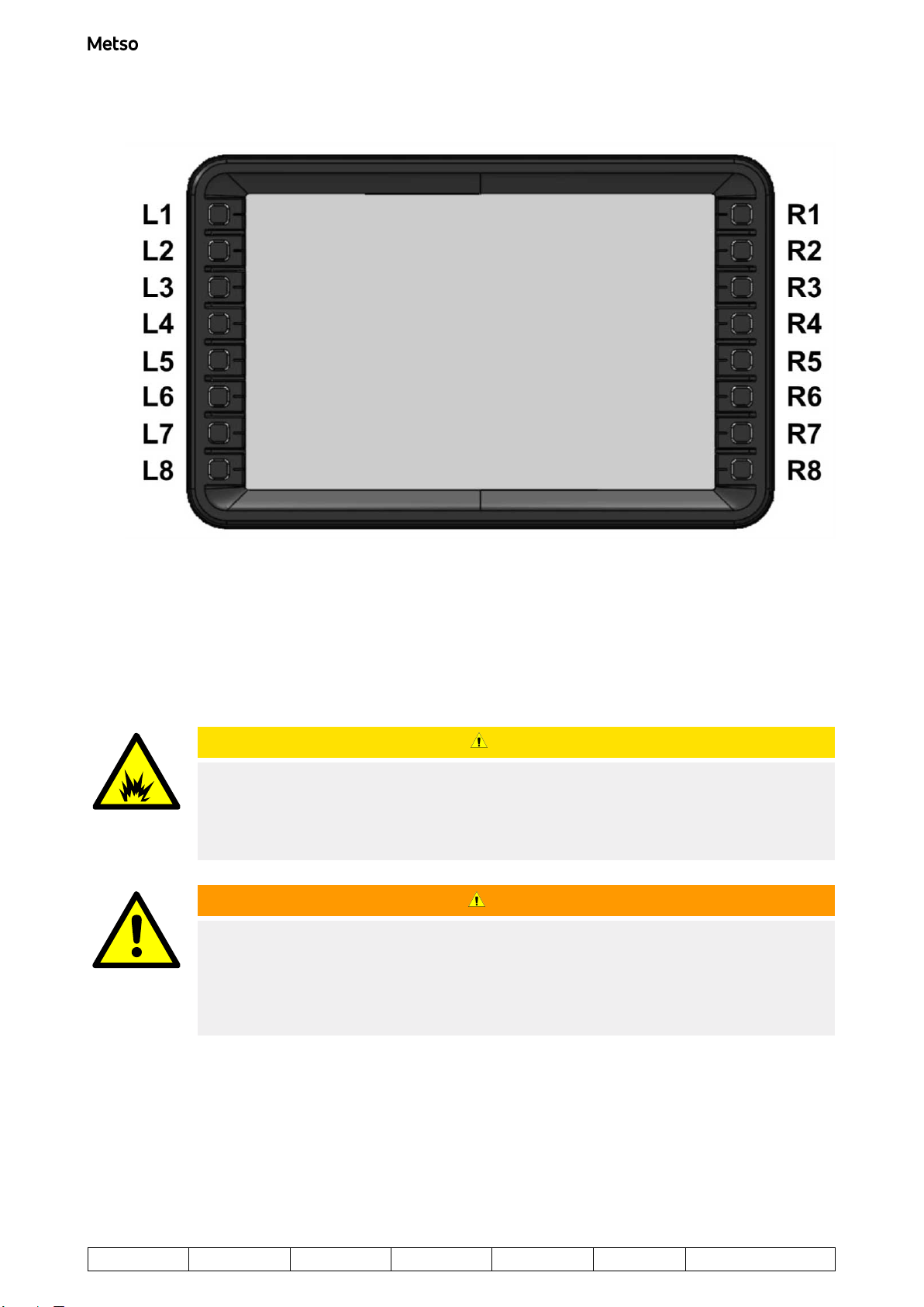
Figure 7. Control panel physical buttons
4. Make sure that the emergency stop buttons are not pressed, and that the remote stop button is not
pressed down.
5. Proceed to the next section: “Starting the engine”.
1.1.6.1 Starting the engine
CAUTION
EXPLOSION HAZARD
Can cause moderate injury or property damage.
Never use startup spray or any other similar product to help the engine start. Startup sprays and
similar products can cause a destructive explosion in the intake manifold.
WARNING
PERSONAL INJURY HAZARD
Can cause death or serious injury.
Before starting the machine, make sure that there are no persons in the area whose safety may be
endangered. Walk around the machine and make sure that there is nobody on, by or below the
machine. Warn everybody nearby before starting.
Nordtrack J127 Driving instructions
Copyright © Metso 2023. All rights reserved. 11 (30)
Project ID: Plant Code: Plant Unit Code: Document Type: Running No: Revision:
1
Metso Document ID:
D100020717

WARNING
PERSONAL INJURY HAZARD
Can cause death or serious injury.
Wear personal protective equipment and clothing such as foot protection, helmet, hearing
protection, dust protective devices, safety glasses or other personal protective clothing and
equipment at all times.
For control panel physical button locations, see "Preparing for driving".
1. Observe all safety warnings.
2. Check that all control levers are in neutral (OFF) position, and all emergency stops are released.
CAUTION
PROPERTY DAMAGE HAZARD
Can cause moderate injury or property damage.
Make sure that all control levers are in the neutral (OFF) position.
1
Figure 8. Control levers in neutral (OFF) position
3. Insert the key into the ignition switch of main control panel.
4. Turn the key clockwise to the Power ON position (2). The display will start its boot sequence followed by
entry into the main menu view.
Nordtrack J127 Driving instructions
12 (30) Copyright © Metso 2023. All rights reserved.
Project ID: Plant Code: Plant Unit Code: Document Type: Running No: Revision:
1
Metso Document ID:
D100020717

1
2
3
Figure 9. Ignition key positions
1. OFF
2. Power ON
3. Crank
5. Wait until the engine is pre-heated and the engine pre-heat indicator (see figure below) in the status/
warning bar at the top of the screen disappears before continuing.
Figure 10. Engine pre-heat indicator
6. Turn the key clockwise further to the Crank position (3) and hold it in this position for at least 10 seconds
until the engine starts. During the 10 seconds, you will hear an audible start alarm signal to indicate that
the machine is about to start and a “Pre-crank” countdown (in seconds) is shown on the screen. The
engine cranking indicator is also show in the status bar at the top of the screen.
Figure 11. Pre-crank countdown (left) and engine cranking indicator (right)
7. Release the key immediately after the engine starts.
8. Wait for the clutch to engage and the Clutch Engagement indicator to disappear from the status bar at
the top of the screen:
Figure 12. Clutch engagement indicator
9. Before operating the machine, allow the engine to run at idle for 5 minutes to allow the running
temperature to be reached.
Nordtrack J127 Driving instructions
Copyright © Metso 2023. All rights reserved. 13 (30)
Project ID: Plant Code: Plant Unit Code: Document Type: Running No: Revision:
1
Metso Document ID:
D100020717

10. Check around the engine compartment area for engine oil, fuel, coolant, or hydraulic fluid leaks.
1.1.6.1.1 Adjusting the engine speed
The machine may be fitted with a variable-speed or fixed-speed engine, where a fixed-speed engine has two
speed set-points: idle and 1800 rpm.
NOTE:
For a fixed-speed engine, access to the higher speed of 1800 rpm is restricted in that it can only be
reached once during every engine session. Therefore, if the engine is run at 1800 rpm and then its
speed is reduced, the speed cannot be increased again to 1800 rpm without first stopping and
restarting the engine.
1. From the main view, press the Engine button L2 to enter the Engine Control menu. In the menu, you can
see the buttons for controlling the engine speed (see figure below).
NOTE:
Buttons (2) and (3) only change the engine speed while they are pressed down. Hold down the
relevant button to continuously change the speed. The longer you hold down the button, the
higher the rate at which the speed changes. This allows the desired speed to be reached
quickly.
NOTE:
For a fixed-speed engine, buttons (2) and (3) will not allow continuous change but will change
the engine speed between the two set-points (idle and 1800rpm). Buttons (1) and (4) will also
change the engine speed between idle (minimum) and 1800rpm(maximum).
1
2
3
4
Figure 13. Engine speed adjustment buttons
1. Press to ramp up the engine speed to its
maximum
3. Press to decrease the engine speed
continuously
2. Press to increase the engine speed
continuously
4. Press to ramp down the engine speed to its
minimum
Nordtrack J127 Driving instructions
14 (30) Copyright © Metso 2023. All rights reserved.
Project ID: Plant Code: Plant Unit Code: Document Type: Running No: Revision:
1
Metso Document ID:
D100020717
1.1.6.1.2 Monitoring engine information
You can monitor the engine from the Engine screen.
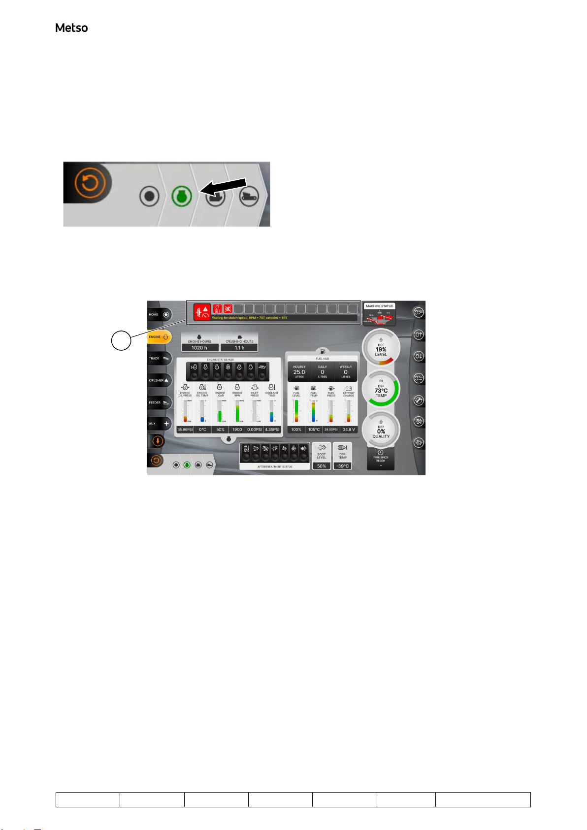
To activate the Engine screen, press button L8 repeatedly until the adjacent Engine symbol is highlighted in
green (see figure below).
Figure 14. Engine screen chosen
The engine screen is shown on the display. The status and warning indicator bar (1) shows all engine
warnings.
1
Figure 15. Engine screen
In the Engine screen, you can view and monitor following information:
Nordtrack J127 Driving instructions
Copyright © Metso 2023. All rights reserved. 15 (30)
Project ID: Plant Code: Plant Unit Code: Document Type: Running No: Revision:
1
Metso Document ID:
D100020717
1
23 4 567 8
14 13 12 11 10 9
16 15
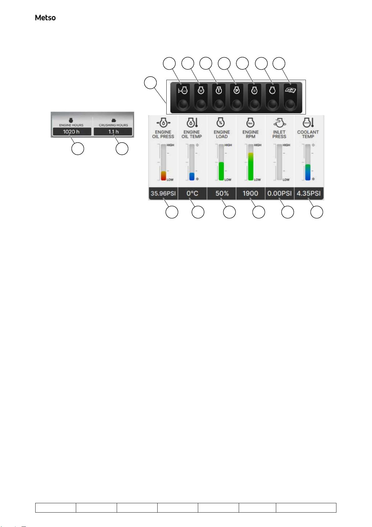
Figure 16. Engine status, engine levels and hours of use
1. Engine status indicators 9. Coolant Temperature: shown in °C or °F.
2. Engine coolant level low: Lamp illuminates in red
when the engine coolant level is low.
10. Inlet Pressure: shown in Bar or PSI.
3. Engine Pre-heat: Lamp illuminates in green
when the engine pre-heat is active.
11. Engine Speed: shown in rpm.
4. Engine Stop: Lamp illuminates in red when an
engine shutdown has been initiated due to a
serious issue.
12. Engine Load: shown as a percentage.
5. Engine Protect: Lamp illuminates in green when
an engine derate has been initiated due to a
serious issue.
13. Engine Oil Temperature: shown in °C or °F (not
available for all engine types).
6. Engine Cold: Lamp illuminates in green when the
engine is cool (engine speed is limited and
machine functions are disabled until the engine
coolant temperature is greater than 30°C).
14. Engine Oil Pressure: shown in Bar or PSI (not
available for all engine types).
7. Engine Warning: Lamp illuminates in green when
an engine fault has been detected.
15. Engine Hours: Total number of hours that the
engine has run (since new).
8. Engine Service Required: Lamp illuminates in
green when an engine service is required.
16. Crushing Hours: Total number of hours that the
crusher has run (since new).
Nordtrack J127 Driving instructions
16 (30) Copyright © Metso 2023. All rights reserved.
Project ID: Plant Code: Plant Unit Code: Document Type: Running No: Revision:
1
Metso Document ID:
D100020717
8 9 10
1
2
3
7 6 5 4
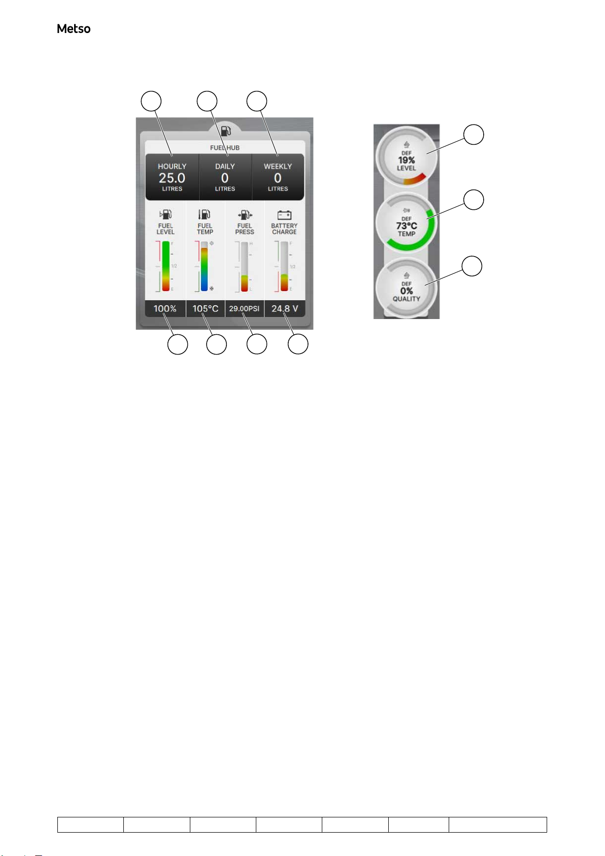
Figure 17. Fuel information, battery voltage and DEF (diesel exhaust fluid)
1. DEF level: shown as percentage. 6. Fuel Temperature: shown in figures in °C or °F.
The bar-chart is colour-coded from bright blue
through green to bright red, where green means
acceptable, blue means too low and red means too
high.
2. DEF temperature: shown in °C or °F. 7. Fuel Level: shown in figures as a percentage of
full capacity.
The bar-chart is colour-coded from bright red to
green, where green means acceptable and red
means too low.
3. DEF quality: shown as percentage. 8. Hourly fuel usage: Average fuel consumption
(litres/gallons) per hour.
4. Battery voltage: shown in voltage (V). 9. Daily fuel usage: Average fuel consumption
(litres/gallons) per day
5. Fuel Pressure: shown in figures in Bar or PSI.
The bar-chart is colour-coded from bright red
through green and back to bright red, where green
means acceptable and red means too high or too
low.
10. Weekly fuel usage: Average fuel consumption
(litres/gallons) per week.
Nordtrack J127 Driving instructions
Copyright © Metso 2023. All rights reserved. 17 (30)
Project ID: Plant Code: Plant Unit Code: Document Type: Running No: Revision:
1
Metso Document ID:
D100020717
2 3 4 5 6 7 8 10 11 12
1
9
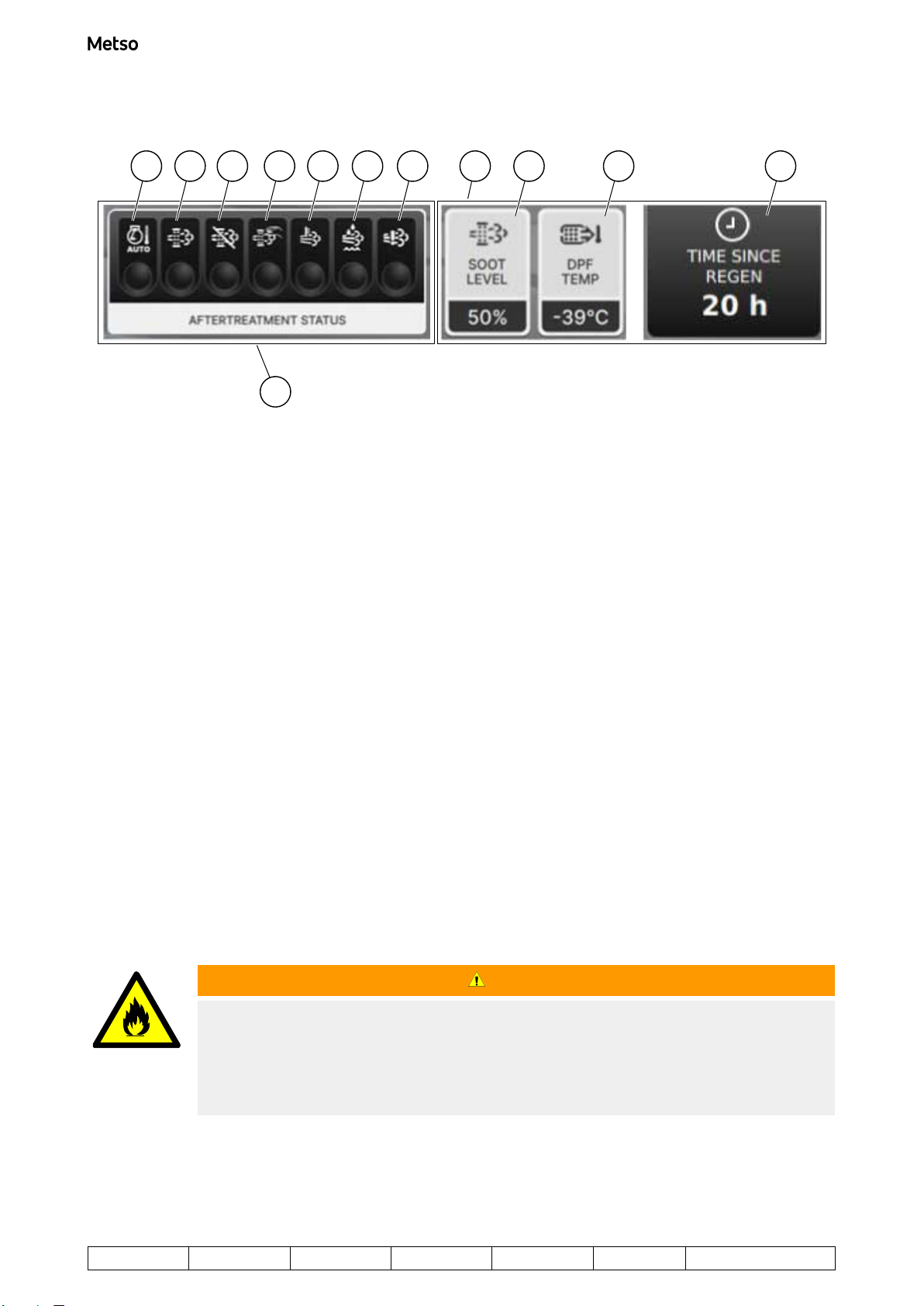
Figure 18. Aftertreatment status (Tier4 only) and DPF (Diesel Particulate Filter) information
1. Aftertreatment status (Tier4 only) 7. DEF Level Low: Lamp illuminates in yellow when
the DEF level is low and needs replenishing.
2. DPF Outlet Gas Over-temperature: Lamp
illuminates in yellow when the temperature of the
outlet gas from the DPF is too high.
8. Emissions System Failure:
• Lamp illuminates in yellow when the DEF level
is very low
• Lamp flashes in yellow when the DEF level is
extremely low or another emissions system fault
occurs.
3. DPF Regeneration Needed: Lamp illuminates in
yellow when a DPF regeneration is required.
9. DPF (Diesel Particulate Filter) information
4. DPF Regeneration Inhibited: Lamp illuminates in
yellow when automatic DPF regeneration is
inhibited/disabled.
10. DPF soot level: shown as a percentage.
Depending on engine type, can alternate with DPF
ash level (%).
5. Manual DPF Regeneration Active: Lamp
illuminates in yellow when a manual DPF
regeneration has been initiated.
11. DPF temperature: shown in °C or °F.
6. DPF Regeneration with High Exhaust
Temperature: Lamp illuminates in yellow when a
DPF regeneration is in progress and exhaust
temperature is elevated.
12. Time elapsed since the last DPF regeneration:
shown in hours.
1.1.6.1.3 Preventing and initiating DPF generation
WARNING
FIRE HAZARD
Can cause death or serious injury.
Stay away from the exhaust pipe. Do not place any flammable objects in front of the exhaust pipe.
The exhaust gas is very hot. Note that the exhaust gas can be even hotter during regeneration of
the diesel particulate filter.
Nordtrack J127 Driving instructions
18 (30) Copyright © Metso 2023. All rights reserved.
Project ID: Plant Code: Plant Unit Code: Document Type: Running No: Revision:
1
Metso Document ID:
D100020717

1. To prevent diesel particulate filter regeneration, press button R6 corresponding to the following icon in
the Engine Control menu:
Figure 19. Preventing DPF regeneration
2. If needed, initiate diesel particulate filter regeneration manually by pressing button R7 corresponding to
the following icon in the Engine Control menu:
Figure 20. Initiating DPF regeneration
1.1.6.2 Connecting the remote control device (wireless connection)
NOTE:
The remote control device can be used as either a wired control device or a wireless control device.
Using the wireless connection is recommended. When the remote control device is connected with
the wired connection, it will charge the remote control device. When not connected with the wired
connection, the remote control device can be used once it is paired to the wireless signal of the
machine. The remote control device can also be charged by using the portable charger.
NOTE:
Before the remote control device can be used in wireless (radio) mode, it must be charged
• through either a wired connection with the machine,
• or through a separate remote control device charger provided with the machine.
If the wireless connection does not work, see "Pairing the remote control device to the machine".
1.1.6.3 Connecting the remote control device (wired connection)
WARNING
UNEXPECTED MOVEMENT HAZARD
Can cause death or serious injury.
Before taking the drive control device into use, check visually that the drive control device, cable or
plugs are not damaged. Also make sure that the connectors are clean and that there is no moisture
in the plug or connectors.
To establish a wired connection between the remote control device and machine, or to charge the remote
control device for wireless use:
1. Connect the cable (1) to the socket on the base of the remote control device (2) and the other end of the
cable to the socket on the machine (3).
Nordtrack J127 Driving instructions
Copyright © Metso 2023. All rights reserved. 19 (30)
Project ID: Plant Code: Plant Unit Code: Document Type: Running No: Revision:
1
Metso Document ID:
D100020717
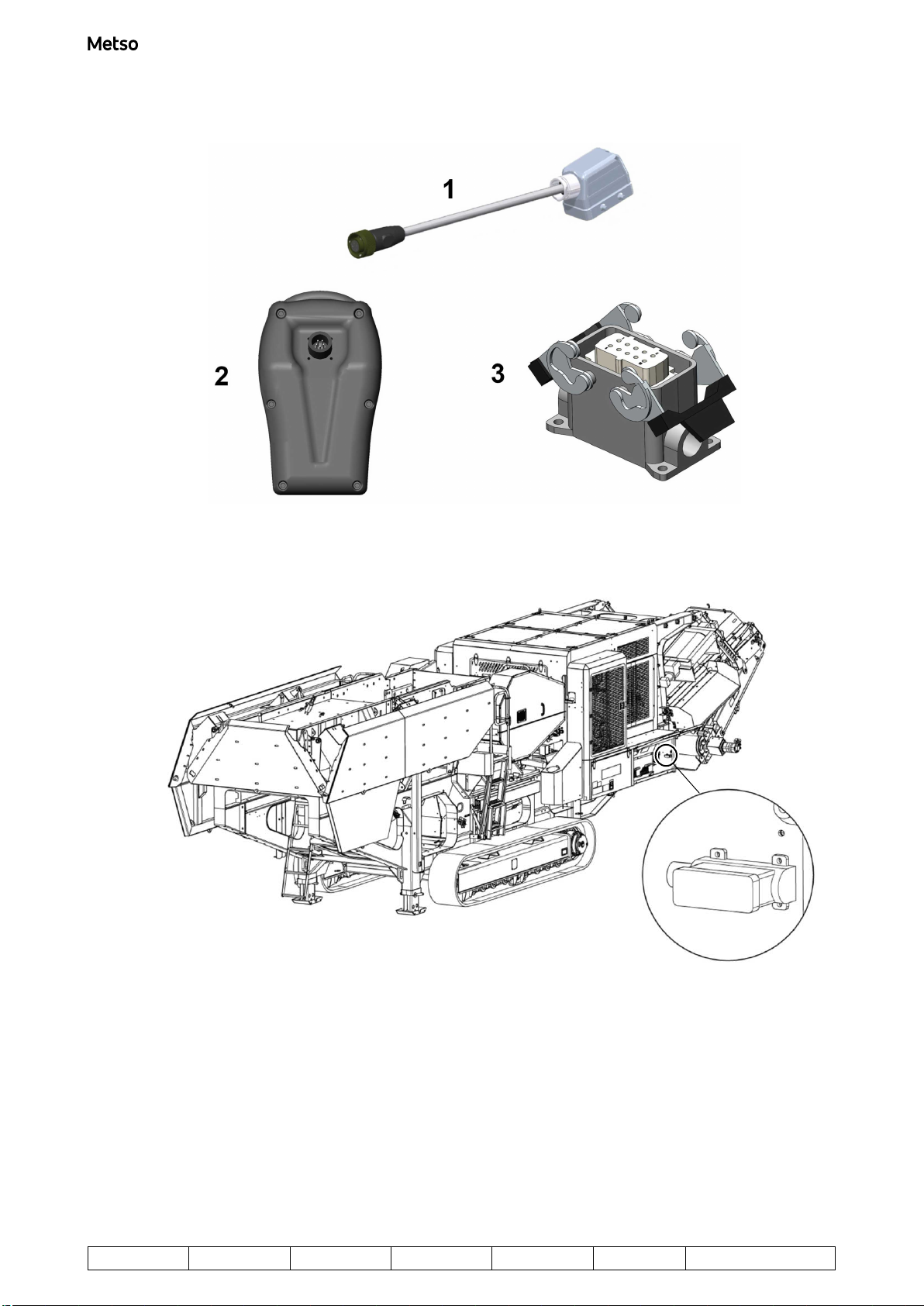
Figure 21. Connection items for remote control device
Figure 22. Socket location for the cable
2. You can now unlock the remote control device for wired use, as described in "Unlocking the remote
control device".
Alternatively, you can leave the remote control device to charge for wireless use – the Lock LED on the
remote control device flashes red during charging and is extinguished when the remote control device is
fully charged.
Nordtrack J127 Driving instructions
20 (30) Copyright © Metso 2023. All rights reserved.
Project ID: Plant Code: Plant Unit Code: Document Type: Running No: Revision:
1
Metso Document ID:
D100020717
Table of contents
Other Metso Industrial Equipment manuals

Metso
Metso NORDBERG C Series User manual

Metso
Metso Nordtrack J90 User manual

Metso
Metso NORDBERG LT105 User manual

Metso
Metso HP Series Installation instructions

Metso
Metso JAMESBURY CC Series Operating and maintenance manual

Metso
Metso Nordberg MP Series Product manual

Metso
Metso Lokotrack ST2.8 User manual

Metso
Metso Nordberg GP200S User manual

Metso
Metso Nordtrack J90 User manual

Metso
Metso LOKOTRACK LT110C User manual


