manuals.online logo
Brands
  1. Home
  2. •
  3. Brands
  4. •
  5. Metso
  6. •
  7. Switch
  8. •
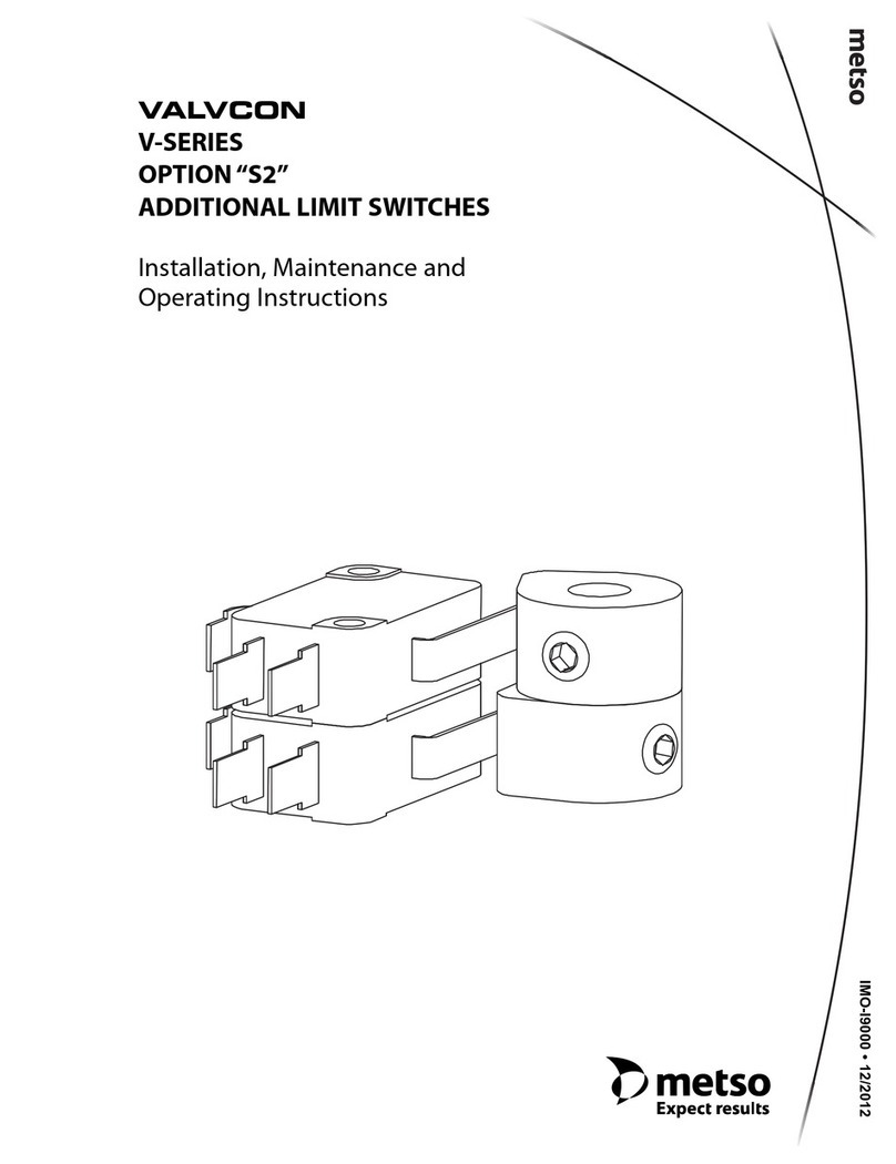
  9. Metso Valvcon LCU Series Operating and maintenance manual

Metso Valvcon LCU Series Operating and maintenance manual

VALVCON
LCU-SERIES
OPTION“S2”
ADDITIONAL LIMIT SWITCHES
Installation, Maintenance and
Operating Instructions
IMO-I1478 • 4/2013
Table of Contents
1 GENERAL . . . . . . . . . . . . . . . . . . . . . . . . . . . . . . . . . . . . 3
1.1 Description . . . . . . . . . . . . . . . . . . . . . . . . . . . . . . . . . 3
1.2 Applicability . . . . . . . . . . . . . . . . . . . . . . . . . . . . . . . . 3
2 PARTS LIST. . . . . . . . . . . . . . . . . . . . . . . . . . . . . . . . . . . 3
3 TOOLS REQUIRED . . . . . . . . . . . . . . . . . . . . . . . . . . . . 3
4 INSTALLATION . . . . . . . . . . . . . . . . . . . . . . . . . . . . . . . 3
2IMO-I1478
READ THESE INSTRUCTIONS FIRST!
These instructions provide information about safe handling and operation of the actuator.
If you require additional assistance, please contact the manufacturer or manufacturer's representative.
Addresses and phone numbers are printed on the back cover.
See also www.metso.com/valvcon for the latest documentation.
SAVE THESE INSTRUCTIONS!
Subject to change without notice.
All trademarks are property of their respective owners.
IMO-I1478 3
1 GENERAL
1.1 Description
The LCU-Series Limit Switch Kit adds two additional limit
switches to an actuator. Standard actuators are shipped
from the factory with two limit switches installed—one to
control the end of travel in the fully open position and one
to control the end of travel in the fully closed position.Two
additional limit switches may be installed to provide con-
tact closure at any actuator position.
1.2 Applicability
This Limit Switch Kit is intended for use with any LCU-
Series Electric Actuator.
2 PARTS LIST
2 Limit Switches
2 Cams
2 #4-40 x 2.25" screws
2 Limit Switch Wiring Harnesses
2 Wire Ties
4 #6 x .090" spacers
2 #6 x .150" spacers
2 .090" Cam spacers 3/8" ID, 17/32" OD
1 Cam Shaft Support Bracket
3 TOOLS REQUIRED
Medium Phillips Screwdriver
Small flat blade Screwdriver
3/32" Hex Wrench
4 INSTALLATION
A. Remove Actuator Cover
Remove the actuator cover by removing the screws
securing the cover to the base.
B. Install the Limit Switches, Cams and Cam Shaft
Support Bracket
Remove the Limit Switch screws, which secure the exist-
ing Limit Switches in place, retaining the spacers
between the existing two limit switches.
Replace Limit Switch screws with the #4-40 X 2.25" Screws,
(provided) ; refer to Figure 1 for proper switch, spacer,
cam and cam shaft support bracket orientation.
C. Install Wiring Assembly
1. Attach the faston end of the White Wire to the Com-
mon (COM) connector on the Limit Switch. Connect
the stripped end of the White Wire to terminal num-
ber 8 on the terminal strip.
2. Attach the faston end of the Black Wire to the Normal-
ly Open (NO) connector on the Limit Switch. Connect
the stripped end of the Black Wire to terminal number
9 on the terminal strip.
3. Attach the faston end of the Red Wire to the Normally
Closed (NC) connector on the Limit Switch. Connect
the stripped end of the Red Wire to terminal number 7
on the terminal strip.
4. Using the supplied Wire Tie, secure the Limit Switch
wires to avoid contact with any moving parts.
D. Install Cam
1. Slide the additional Cam down the actuator cam shaft
on top of the existing Cams.
2. Drive the actuator to the desired trip point.
3. Rotate the cam counterclockwise until the limit switch
lever passes through one of the flats on the cam and
operates the limit switch (pushes the lever in). Now
rotate the cam clockwise until the limit switch just
clicks open.
4. Re-tighten the set screw in the limit switch cam. (Do
not over-tighten the screws, use less than 8 in/lbs of
tightening torque)
5. Operate the actuator to verify proper setting of the
Cam.
Cam Shaft
Support Bracket
#4-40 x 2.25"
#6 x 0.150" Spacers
#6 x 0.90" Spacers
0.90" Cam Spacers
Cams
Cam Shaft Support Bracket Bearing
(Factory Installed)
Limit Switches
and Harnesses
Figure 1 Parts Identification
CAUTION:
Dangerous voltages are present inside the actuator cover unless
the power supply to the actuator has been shut off or disconnect-
ed. Use extreme caution whenever working on the actuator with
the cover removed.
4IMO-I1478
Metso Automation Inc.
Europe, Vanha Porvoontie 229, P.O. Box 304, FI-01301 Vantaa, Finland, Tel. +358 20 483 150, fax +358 20 483 151
North America, 44 Bowditch Drive, P.O.Box 8044, Shrewsbury, Massachusetts, 01545-8044 USA. Tel. int. +1 508 595 5083. Fax int. +1 508 595 5183
www.metso.com/valvcon
Subject to change without prior notice.
AC NEUTRAL/L1
AC HOT, OPT. HEATER/L2
AC HOT, 0 & 180 CONTROL
AC HOT, 90 & 270 CONTROL
0 & 180 INDICATION
90 & 270 INDICATION
NC
AUX.LIMIT SWITCH COM
NO
NC
AUX.LIMIT SWITCH COM
NO
BLK
WHT
WHT
RED
RED
RED
WHT
BLK
RED
WHT
BLK
COM
COM
COM
COM
NO BLK
NC
NO BLK
NC
NC
NO
NC
NO
MOTOR
TERMINAL
STRIP
1
2
3
4
5
6
7
8
9
10
11
12
Figure 2 LCU-Series AC Wiring
DC NEGATIVE
DC POSITIVE, OPT. HEATER
DC POSITIVE,0 & 180 CONTROL
DC POSITIVE,90 & 270 CONTROL
0 & 180 INDICATION
90 & 270 INDICATION
NC
AUX.LIMIT SWITCH COM
NO
NC
AUX.LIMIT SWITCH COM
NO
BLK
WHT
WHT
RED
RED
RED
WHT
BLK
RED
WHT
BLK
COM
COM
COM
COM
NO BLK
NC
NO BLK
NC
NC
NO
NC
NO
MOTOR
TERMINAL
STRIP
1
2
3
4
5
6
7
8
9
10
11
12
Figure 3 LCU-Series DC Wiring
E. Replace Actuator Cover
NOTE: When reinstalling the cover, follow the normal
practice of tightening the cover screws in a cross pattern
to insure that the cover is pulled down flat without over-
stressing a corner.

Other Metso Switch manuals

Metso Neles Quartz LIMIT SWITCH Operating and maintenance manual

Metso

Metso Neles Quartz LIMIT SWITCH Operating and maintenance manual

Metso PDP Series Operating instructions

Metso

Metso PDP Series Operating instructions

Metso VALVCON V-Series Operating and maintenance manual

Metso

Metso VALVCON V-Series Operating and maintenance manual

Popular Switch manuals by other brands

AirLive Live-26G Quick setup guide

AirLive

AirLive Live-26G Quick setup guide

Black Box ServSelect III KV21008A Specifications

Black Box

Black Box ServSelect III KV21008A Specifications

Planet ISW-504PT user guide

Planet

Planet ISW-504PT user guide

Black Box ServSwitch Octet KV1701 instructions

Black Box

Black Box ServSwitch Octet KV1701 instructions

Smart view IC-712-I user manual

Smart view

Smart view IC-712-I user manual

Krom Schroder DL K Series operating instructions

Krom Schroder

Krom Schroder DL K Series operating instructions

HIK VISION DS-3E05 Series installation manual

HIK VISION

HIK VISION DS-3E05 Series installation manual

Black Box ServSwitch ACXCWDM4 user manual

Black Box

Black Box ServSwitch ACXCWDM4 user manual

DuraSat DUR-line MS 9/8 G-HQ installation manual

DuraSat

DuraSat DUR-line MS 9/8 G-HQ installation manual

Planet GS-4210 SERIES Quick installation guide

Planet

Planet GS-4210 SERIES Quick installation guide

Ruby Tech PSGS-2112C Specifications

Ruby Tech

Ruby Tech PSGS-2112C Specifications

Black Box KV9316A-R2 Specifications

Black Box

Black Box KV9316A-R2 Specifications

SMART-AVI HDN-4DUO quick start guide

SMART-AVI

SMART-AVI HDN-4DUO quick start guide

FOR-A MFR-6000R Quick setup guide

FOR-A

FOR-A MFR-6000R Quick setup guide

HIK VISION 0500P Series quick start guide

HIK VISION

HIK VISION 0500P Series quick start guide

Connect Pro Master-IT StreamLine SL-18 user guide

Connect Pro

Connect Pro Master-IT StreamLine SL-18 user guide

Vivo Link VL120014 user manual

Vivo Link

Vivo Link VL120014 user manual

Planet IPM-8221 user manual

Planet

Planet IPM-8221 user manual

manuals.online logo
manuals.online logoBrands
  • About & Mission
  • Contact us
  • Privacy Policy
  • Terms and Conditions

Copyright 2025 Manuals.Online. All Rights Reserved.