manuals.online logo
Brands
  1. Home
  2. •
  3. Brands
  4. •
  5. Krom Schroder
  6. •
  7. Switch
  8. •
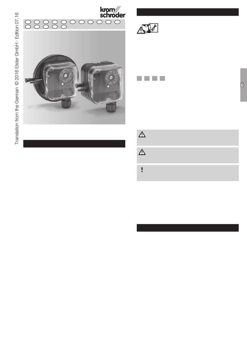
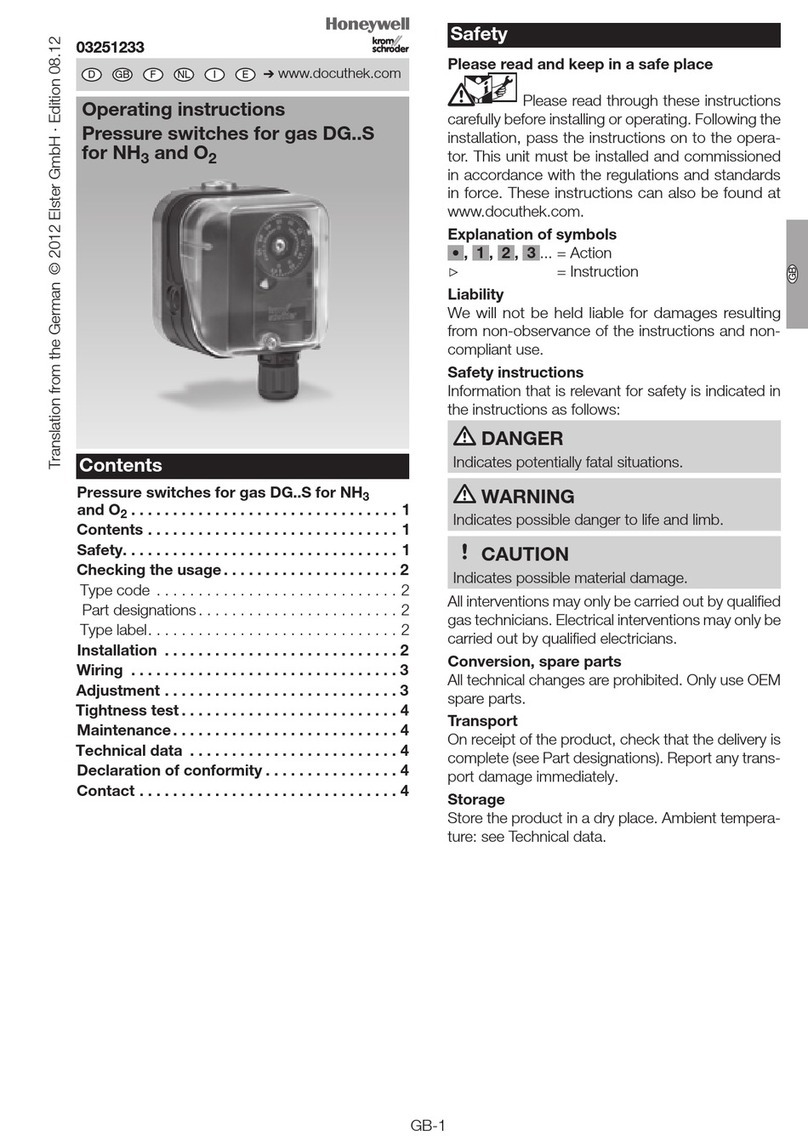
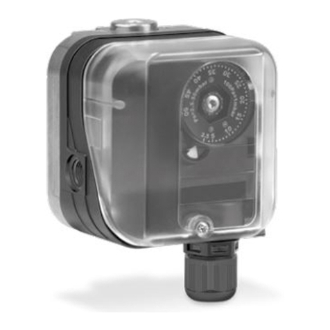
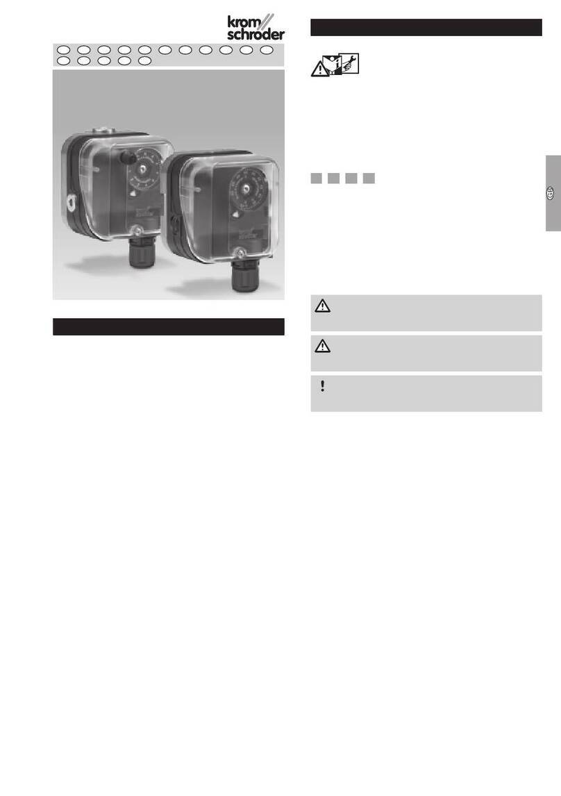
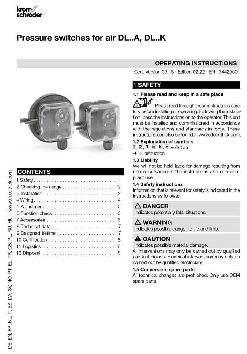
  9. Krom Schroder DL K Series User manual

Krom Schroder DL K Series User manual

DK S N P GR
➔www.docuthek.com
D GB F NL I E
TR CZ PL RUS H
Cert-Version 09.13
© 2013 Elster GmbH · Edition 09.13
Safety
Please read and keep in a safe place
Please read through these instructions
carefully before installing or operating. Following the
installation, pass the instructions on to the opera-
tor. This unit must be installed and commissioned
in accordance with the regulations and standards
in force. These instructions can also be found at
www.docuthek.com.
Explanation of symbols
• , 1 ,  , 3 ... = Action
▷= Instruction
Liability
We will not be held liable for damage resulting from
non-observance of the instructions and non-com-
pliant use.
Safety instructions
Information that is relevant for safety is indicated in
the instructions as follows:
DANGER
Indicates potentially fatal situations.
WARNING
Indicates possible danger to life and limb.
CAUTION
Indicates possible material damage.
All interventions may only be carried out by qualified
gas technicians. Electrical interventions may only be
carried out by qualified electricians.
Conversion, spare parts
All technical changes are prohibited. Only use OEM
spare parts.
Transport
On receipt of the product, check that the delivery is
complete (see Part designations). Report any trans-
port damage immediately.
Storage
Store the product in a dry place. Ambient tempera-
ture: see Technical data.
Changes to edition 10.1
The following chapters have been changed:
– New layout:
Installation
Wiring
Adjustment
Accessories
Technical data
Declaration of conformity
Contents
Operating instructions
D
GB
F
NL
I
E
GB-1
035005
Translation from the German
Pressure switches for air DL..K
Pressure switches for air DL..K ........... 1
Contents ..............................1
Safety.................................1
Checking the usage .....................
Type code .............................2
Part designations ........................2
Type label..............................2
Installation ............................
Wiring ................................3
Adjustment ............................3
Maintenance ...........................4
Accessories ...........................4
Technical data .........................4
Declaration of conformity ................4
Contact ...............................4
Safety
Contents
GB-2
D
GB
F
NL
I
E
Checking the usage
DL..K
For monitoring positive, negative or differential air or
flue gas pressures.
This function is only guaranteed when used within the
specified limits– see page4 (Technical data). Any
other use is considered as non-compliant.
Type code
Code Description
DL Pressure switch for air
3,3 – 40 Max. setting in Pa
KWith tube connection and hand wheel
for adjustment
TT-product
GGold contacts
-1
-3
Electrical connection
via AMP plugs
via screw terminals
K
N
T
T
Red/green pilot LED 24VDC/AC
Blue pilot lamp 120VAC
Blue pilot lamp 230VAC
Red/green pilot LED 230VAC
WZ-angle bracket
Part designations
1
2
3
4
1Upper housing section with cover
Lower housing section
3Hand wheel
4M16 cable gland
Type label
Mains voltage, switching pressure, ambient tempera-
ture and enclosure: see type label.
Osnabrück, Germany
DL..K
Installation
CAUTION
Please observe the following to ensure that the
DL..K is not damaged during installation and op-
eration:
– Condensation must not be allowed to get into
the housing (if possible, install pipework with an
ascending gradient). Otherwise, there is a risk of
icing of condensation at subzero temperatures,
the switching point shifting or corrosion in the
device which can lead to malfunctions.
– In the case of uneven ground, secure the pres-
sure switch to the mounting plate or air duct
with only two screws on the same side in order
to avoid subjecting the pressure switch to me-
chanical stress.
– Protect the connections against dirt or moisture
in the medium to be measured or the surround-
ing air. If necessary, install a filter.
– When using silicone tubes, only use silicone
tubes which have been sufficiently cured. Va-
pours containing silicone can adversely affect
the functioning of electrical contacts.
– In case of highly fluctuating pressures, install a
damping nozzle.
▷
Installation in the vertical or horizontal position, or
upside down, preferably with vertical diaphragm.
If installed in a vertical position, the switching
pointpSwill correspond to the scale valueSK.
If installed in another position, the switching
pointpSwill change and no longer correspond
to the set scale valueSK. Switching pointp
S
must be checked.
ps= SK SK + 13 Pa
[+ 0.052 "WC]
SK - 13 Pa
[- 0.052 "WC]
1 Install the DL using screws, a securing clip or an
angle bracket.
66 4,4
(0.14")
ø 6,1
(ø 0.24")
(2.6")
2 22
▷Tube connection: Ø 6 mm (0.236").
▷Max. inlet presure pmax. = 5000 Pa (20"WC).
GB-3
D
GB
F
NL
I
E
Wiring
CAUTION
Please observe the following to ensure that the
DL..K is not damaged during operation:
– If the DL..G (DL..TG) has switched a volt-
age >24V (>30V) and a current >0.1A at
cosφ=1 or >0.05A at cosφ=0.6 once,
the gold plating on the contacts will have been
burnt through. It can then only be operated at
this power rating or higher power rating.
– Note the switching capacity, see page 4
(Technical data).
▷
In the case of high humidity, we recommend
using a pressure switch with gold contact due to
its higher resistance to corrosion. Closed-circuit
current monitoring is recommended under dif-
ficult operating conditions.
▷In the case of low switching capacities, such as
24V, 8mA, for example, we recommend using
an RCmodule (22Ω, 1μF) in air containing
silicone or oil.
1 Disconnect the system from the electrical power
supply.
M16 x 1,5:
∅4,5 – 10 mm
COM
3
NC
1
NO
2
NO
2NC
1
COM
3
L1(+) 54
32
Adjustment
▷
The switching pressure can be adjusted using the
hand wheel and scale. The switching pressure
differs from the adjusted setpoint by a maximum
of ±15%, when it has been set for increasing
pressure and with a vertical diaphragm.
Type
Adjusting
range
[Pa]
Mean
switching
differential
at min. and
max. setting
[Pa]
Deviation from
the switching
point during
testing
pursuant to
EN 1854 or
by agreement
min. max. min. max.
DL 3,3K 20 330 820 ± 7 Pa/± 15%
DL 3,5K 30 350 10 20 ± 5 Pa/± 15%
DL 4,5K 30 500 12 25 ± 5 Pa/± 15%
DL 5,1K 100 510 15 30 ± 15%
DL 8K 50 800 17 30 ± 14
Pa/± 15%
DL 11K 100 1100 20 35 ± 20
Pa/± 15%
DL 16K 400 1600 30 40 ± 15%
DL 24K 200 2400 45 55 ± 40
Pa/± 15%
DL 40K 500 4000 70 90 ± 15%
Type
Adjusting
range
["WC]
Mean
switching
differential
at min.
and max.
setting
["WC]
Deviation from
the switching
point during
testing pursuant
to EN 1854 or
by agreement
min. max. min. max.
DL 3,5KT 0.12 1.4 0.04 0.08 ± 0.02
"WC/± 15%
DL 4,5KT 0.12 20.05 0.10 ± 0.02
"WC/± 15%
DL 8KT 0.20 3.2 0.07 0.12 ± 0.06
"WC/± 15%
DL 11KT 0.4 4.4 0.08 0.14 ± 0.08
"WC/± 15%
DL 16KT 1.6 6.4 0.12 0.16 ± 15%
DL 24KT 0.8 9.6 0.18 0.22 ± 0.16
"WC/± 15%
DL 40KT 2.0 16.0 0.28 0.36 ± 15%
1 Disconnect the system from the electrical power
supply.
+
+
1
NC
2
NO
3
COM
Ω
54
32
NO
2
NC
1
COM
3
Elster GmbH
Postfach 28 09, D-49018 Osnabrück
Strotheweg 1, D-49504 Lotte (Büren)
T +49 541 1214-0
F +49 541 1214-370
GB-4
D
GB
F
NL
I
E
Contact
If you have any technical questions, please contact
your local branch office/agent. The addresses are
available on the Internet or from ElsterGmbH.
We reserve the right to make technical modifications
in the interests of progress. info@kromschroeder.com, www.kromschroeder.com
Contact
Maintenance
▷We recommend a function check once a year.
Accessories
Angle brackets, securing clips and other acces-
sories, see Technical Information DL (D, GB, F)–
www.docuthek.com
Tube set
2m PVC tube, 2duct connection flanges with screws,
including angle connectors and extension. Order
No.: 74919272.
Technical data
Gas types: air or flue gas, no flammable gases, no
aggressive gases.
Micro switch to EN 61058-1,
switching capacity:
DL..K: 24 V (min. 0.05 A) to 250 V AC
(max. 5 A, at cos ϕ0.6 = 1 A),
DL..KG: 5 V (min. 0.01 A) to 250 V AC
(max. 5 A, at cos ϕ0.6 = 1 A),
5 V (min. 0.01 A)
to 48 V DC (max. 1 A),
DL..KT: 30 – 240 V AC, 50/60 Hz,
5 A resistive or
0.5 A inductive (cos ϕ= 0.6),
DL..KTG: < 30 V AC/DC,
0.1 A resistive or
0.05 A inductive (cos ϕ= 0.6).
Ambient temperatures:
DL..K: -15 to +85°C (+5 to +185°F),
DL..KT: -40 to +60°C (-40 to +140°F).
Line entrance: M16 × 1.5,
cable diameter: 4.5 to 10 mm.
Enclosure to IEC 60529: IP54.
Diaphragm: tempered LSR diaphragm system.
Max. inlet pressure puor differential pressure:
5kPa.
Permitted ambient temperature in operation:
DL..K: -15 to +85°C (+5 to +185°F),
DL..KT: -40 to +60°C (-40 to +140°F).
Storage and transport temperature:
-40 to +85°C (-40 to +185°F).
Weight: 125 g (4.4 oz).
Declaration of conformity
We, the manufacturer, hereby declare that the product
DL..K, marked with product ID No. CE-0085AP0466,
complies with the requirements of the listed Directives
and Standards.
Directives: 2009/142/EC, 2006/95/EC
Standards: EN 1854
The relevant product corresponds to the type tested
by the notified body 0085. The production is subject
to the surveillance procedure pursuant to annexII,
paragraph3 of Directive 2009/142/EC and pursuant
to DINENISO9001:2008.
Elster GmbH
Scan of the Declaration of conformity (D, GB) – see
www.docuthek.com
RoHS compliant

This manual suits for next models

9

Other Krom Schroder Switch manuals

Krom Schroder DG B Series User manual

Krom Schroder

Krom Schroder DG B Series User manual

Krom Schroder DG**H series User manual

Krom Schroder

Krom Schroder DG**H series User manual

Krom Schroder DL H Series User manual

Krom Schroder

Krom Schroder DL H Series User manual

Krom Schroder DG**H series User manual

Krom Schroder

Krom Schroder DG**H series User manual

Krom Schroder CPS 1000 User manual

Krom Schroder

Krom Schroder CPS 1000 User manual

Krom Schroder DL 1,5A User manual

Krom Schroder

Krom Schroder DL 1,5A User manual

Krom Schroder DL H Series User manual

Krom Schroder

Krom Schroder DL H Series User manual

Krom Schroder DL A Series User manual

Krom Schroder

Krom Schroder DL A Series User manual

Krom Schroder DG..S Series User manual

Krom Schroder

Krom Schroder DG..S Series User manual

Popular Switch manuals by other brands

enphase Enpower EP200G101-M240US00 Quick install guide

enphase

enphase Enpower EP200G101-M240US00 Quick install guide

TRENDnet TEG-2248WS - Gigabit Web Smart Switch Specifications

TRENDnet

TRENDnet TEG-2248WS - Gigabit Web Smart Switch Specifications

NETGEAR GS308PP installation guide

NETGEAR

NETGEAR GS308PP installation guide

Grizzly T26673 instructions

Grizzly

Grizzly T26673 instructions

HPE FlexFabric 5700 Series Network management and monitoring configuration guide

HPE

HPE FlexFabric 5700 Series Network management and monitoring configuration guide

SWI L-Series Installation and operation manual

SWI

SWI L-Series Installation and operation manual

Reliance Controls PRI/TRAN 2 RN Series Installation and operating instructions

Reliance Controls

Reliance Controls PRI/TRAN 2 RN Series Installation and operating instructions

IDK MSD-402 Command reference guide

IDK

IDK MSD-402 Command reference guide

Digitus DS-11402-1 user manual

Digitus

Digitus DS-11402-1 user manual

Lanberg RS Series Quick installation guide

Lanberg

Lanberg RS Series Quick installation guide

Seastar Solutions pro-trim PT1000 installation manual

Seastar Solutions

Seastar Solutions pro-trim PT1000 installation manual

ZyXEL Communications METRO 2000 datasheet

ZyXEL Communications

ZyXEL Communications METRO 2000 datasheet

ARMTEL IPN-8U user manual

ARMTEL

ARMTEL IPN-8U user manual

WEIGL ProCommander LX Wiring diagram

WEIGL

WEIGL ProCommander LX Wiring diagram

Endress+Hauser Nivotester FTL325N-1 1 manual

Endress+Hauser

Endress+Hauser Nivotester FTL325N-1 1 manual

KELCO D40 Installation and operating instructions

KELCO

KELCO D40 Installation and operating instructions

Lucent Technologies 4ESS manual

Lucent Technologies

Lucent Technologies 4ESS manual

CTS SWH-2108 user guide

CTS

CTS SWH-2108 user guide

manuals.online logo
manuals.online logoBrands
  • About & Mission
  • Contact us
  • Privacy Policy
  • Terms and Conditions

Copyright 2025 Manuals.Online. All Rights Reserved.