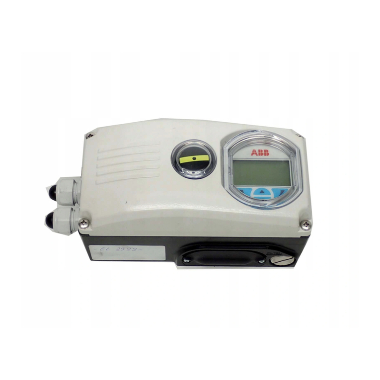
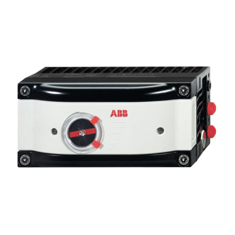
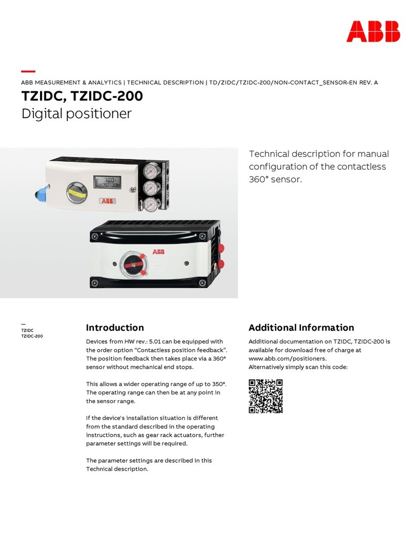
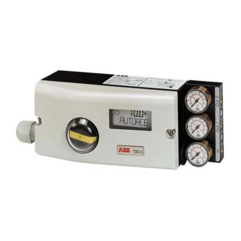
ABB TZIDC-200 User manual

—
ABB MEASUREMENT & ANALYTICS |
COMMISSIONING INSTRUCTION | CI/TZIDC-200/C-FM-US-EN REV. B
TZIDC
-200
Digital positioner
—
ABB Measurement & Analytics
For your local ABB contact, visit:
www.abb.com/contacts
For more product information, visit:
www.abb.com/positioners
cFMus
Digital positioner
for the
positioning of pneumatically
controlled final control elements.
CI/TZIDC
-200/C-FM-US-EN Rev. B 09.2023
—
TZIDC
-200
Introduction
The
TZIDC-200 has an integral mount design,
features a modular structure and offers an
outstanding price
-performance ratio. Fully
automatic determination of the control
parameters and adaptation to the final control
element allow for considerable time savings as
well a
s optimum control behavior.
Additional Information
Additional documentation on
TZIDC-200 is available
for download free of charge at
www.abb.com/
positioners.
Alternatively simply scan this code
:
—
We reserve the right to make technical changes or modify the contents of this
document without prior notice. With regard to purchase orders, the agreed particulars
shall prevail.
ABB does not accept any responsibility whatsoever for
potential errors or possible lack
of information in this document.
We reserve all rights in this document and in the subject matter and illustrations
contained therein. Any reproduction, disclosure to third parties or utilization of its
contents
– in whole or in parts – is forbidden without prior written consent of ABB.
© ABB 2023 3KXE341208R4401

2 TZIDC-200 DIGITAL POSITIONER | CI/TZIDC-200/C-FM-US-EN REV. B
Table of contents
1Safety.......................................................................... 3
General information and instructions................................... 3
Warnings...................................................................................... 3
Intended use ............................................................................... 3
Improper use............................................................................... 3
Cable glands................................................................................ 3
Cyber security disclaimer.........................................................4
Software downloads.................................................................4
Manufacturer’s address ...........................................................4
Service address ..........................................................................4
2Use in potentially explosive atmospheres .............5
General requirements ............................................................... 5
Approvals and certifications ...................................................5
Explosion protection approvals ........................................ 5
Standards applied ................................................................ 5
Product identification............................................................... 5
cFMus ...........................................................................................6
Ex marking..............................................................................6
Electrical Data........................................................................6
Commissioning, installation ..............................................6
Special conditions for the safe use of intrinsically safe
positioners ............................................................................. 7
Use, operation ....................................................................... 7
Maintenance, repair.............................................................. 8
Fault elimination ...................................................................8
Warning markings.................................................................9
FM installation drawing No. 901265 ...............................10
3Product identification ............................................ 15
Name plate ................................................................................ 15
4Transport and storage............................................ 16
Inspection.................................................................................. 16
Transporting the device......................................................... 16
Storing the device.................................................................... 16
Ambient conditions............................................................ 16
Returning devices .................................................................... 16
5Installation ............................................................... 17
Safety instructions .................................................................. 17
Mechanical mounting.............................................................. 17
Measurement and operating range to HW-Rev.: 5.0... 17
Measurement and operating range from HW-Rev.: 5.01
with optional contactless position feedback............... 19
Mounting on linear actuators ..........................................20
Mounting on rotary actuator............................................23
6Electrical connections .............................................25
Safety instructions.................................................................. 25
TZIDC-200 terminal assignment.......................................... 26
Electrical data for inputs and outputs ................................27
Option modules...................................................................27
Connection on the device...................................................... 28
Conductor cross-section.................................................. 29
7Pneumatic Connections ......................................... 30
Safety instructions.................................................................. 30
Information on double acting actuators with spring-
return mechanism.............................................................. 30
Notes on ABB pressure gauge blocks............................ 30
Connection on the device.......................................................31
Air supply....................................................................................31
8Commissioning ........................................................32
Operating modes .....................................................................32
Standard automatic adjustment..........................................33
Standard automatic adjustment for linear actuators*
.................................................................................................33
Standard automatic adjustment for rotary actuators*
.................................................................................................33
Sample parameters .................................................................33
Setting the mechanical position indication ................. 34
Setup of the feedback on the actuator position using
proximity switches............................................................. 34
Setup of the feedback on the actuator position using
microswitches..................................................................... 35
9Operation..................................................................35
Safety instructions.................................................................. 35
Parameterization of the device............................................ 35
Menu navigation ................................................................. 35
Menu levels ............................................................................... 36
10 Maintenance .............................................................37
11 Recycling and disposal............................................37
12 Additional documents.............................................37
13 Appendix .................................................................. 38
Return form .............................................................................. 38

TZIDC-200 DIGITAL POSITIONER | CI/TZIDC-200/C-FM-US-EN REV. B 3
1Safety
General information and instructions
These instructions are an important part of the product and
must be retained for future reference.
Installation, commissioning, and maintenance of the product
may only be performed by trained specialist personnel who have
been authorized by the plant operator accordingly. The specialist
personnel must have read and understood the manual and must
comply with its instructions.
For additional information or if specific problems occur that are
not discussed in these instructions, contact the manufacturer.
The content of these instructions is neither part of nor an
amendment to any previous or existing agreement, promise or
legal relationship.
Modifications and repairs to the product may only be performed
if expressly permitted by these instructions.
Information and symbols on the product must be observed.
These may not be removed and must be fully legible at all times.
The operating company must strictly observe the applicable
national regulations relating to the installation, function testing,
repair and maintenance of electrical products.
Warnings
The warnings in these instructions are structured as follows:
DANGER
The signal word ‘DANGER’ indicates an imminent danger.
Failure to observe this information will result in death or
severe injury.
WARNING
The signal word ‘WARNING’ indicates an imminent danger.
Failure to observe this information may result in death or
severe injury.
CAUTION
The signal word ‘CAUTION’ indicates an imminent danger.
Failure to observe this information may result in minor or
moderate injury.
NOTICE
The signal word
‘NOTICE’
indicates possible material damage.
Note
‘Note’ indicates useful or important information about the
product.
Intended use
Positioning of pneumatically controlled actuators; designed for
mounting on linear and rotary actuators.
The device is designed for use exclusively within the stated
values on the name plate and in the data sheet.
• The maximum operating temperature must not be exceeded.
• The maximum ambient temperature must not be exceeded.
• The housing's rating must be observed during operation.
Improper use
The following are considered to be instances of especially
improper use of the device:
• For use as a climbing aid, for example for mounting
purposes.
• For use as a bracket for external loads, for example as a
support for piping, etc.
• Material application, for example by painting over the
housing, name plate or welding/soldering on parts.
• Material removal, for example by spot drilling the
housing.
Cable glands
Cable glands should be selected and implemented by the
operator in accordance with their use and application
requirements.
The cable glands must comply with the requirements of
EN 60079-1, EN 60079-7, EN 60079-11 or EN 60079-15.
Especially in Ex applications, the requirements of the
appropriate type of protection should be observed.

4 TZIDC-200 DIGITAL POSITIONER | CI/TZIDC-200/C-FM-US-EN REV. B
… 1 Safety
Cyber security disclaimer
This product is designed to be connected to and to
communicate information and data via a network interface. It is
operator’s sole responsibility to provide and continuously ensure
a secure connection between the product and your network or
any other network (as the case may be).
Operator shall establish and maintain any appropriate measures
(such as but not limited to the installation of firewalls,
application of authentication measures, encryption of data,
installation of anti-virus programs, etc.) to protect the product,
the network, its system and the interface against any kind of
security breaches, unauthorized access, interference, intrusion,
leakage and/or theft of data or information.
ABB and its affiliates are not liable for damages and/or losses
related to such security breaches, any unauthorized access,
interference, intrusion, leakage and/or theft of data or
information.
Software downloads
By visiting the web pages indicated below, you will find
notifications about newly found software vulnerabilities and
options to download the latest software. It is recommended that
you visit this web pages regularly:
www.abb.com/cybersecurity
ABB Library – TZIDC-200 – Software downloads
Manufacturer’s address
ABB AG
Measurement & Analytics
Schillerstr. 72
32425 Minden
Germany
Tel: +49 571 830-0
Fax: +49 571 830-1806
Service address
To find your local ABB contact visit:
www.abb.com/contacts
For more information visit:
www.abb.com/measurement

TZIDC-200 DIGITAL POSITIONER | CI/TZIDC-200/C-FM-US-EN REV. B 5
2Use in potentially explosive atmospheres
General requirements
• The ABB positioner has been approved only for appropriate
and intended use in standard industrial atmospheres. Any
breach of this rule leads to a cancellation of warranty and
manufacturer's responsibility!
• Make sure that only devices which comply with the types of
protection relevant to the applicable zones and categories
are installed.
• All electric equipment has to be suited for the respective
intended use.
Approvals and certifications
The digital positioner TZIDC-200 has a variety of different
explosion protection approvals. The scope of these approvals
extends over the entire EU, Switzerland, and special countries.
They range from explosion protection approvals in accordance
with ATEX directives to internationally recognized approvals
such as IECEx, and additionally include country-specific
explosion protection approvals.
Explosion protection approvals
• cFMus, for details, see page 6.
Standards applied
The standards including the date of issue with the devices are in
compliance are specified in the EU Type examination certificate
and in the declaration of conformity of the manufacturer.
Product identification
Depending on the type of explosion protection, Ex-marking is
attached to the positioner on the left, next to the main name
plate.
This indicates the level of explosion protection and the device's
relevant Ex certificate.

6 TZIDC-200 DIGITAL POSITIONER | CI/TZIDC-200/C-FM-US-EN REV. B
… 2 Use in potentially explosive atmospheres
cFMus
Ex marking
TZIDC
-200
Model number: V18348-a0b2d3efghi
XP / I / 1 / CD / T5 Ta =
-40°C to +82°C;
DIP / II, III / 1 / EFG / T5 Ta =
-40°C to +82°C;
Type 4X
Certificate
FM20US0122X and FM20CA0061X
Model number details
a Housing / assembly: 1, 2, 3 or 4
b Operation: 0 or 1
d Set output / safety position: 1, 2, 3 or 4.
d Optional upgrade with plug-in module for analog / digital
feedback (option): 0, 1, 3 or 4
f Optional upgrade with mechanical digital feedback 0, 1, 2, 3.
g Parameterization / bus address: 1 or 2
h Design (paint / marking): 1, H, P or 2
i Measuring point tag plate: 0, 1 or 2
Electrical Data
Refer to FM installation drawing No. 901265 on page 10.
Commissioning, installation
The ABB positioner has to be mounted in a major system.
Depending on the degrees of IP-protection, an interval for
cleaning the equipment (dust settlement) has to be defined.
Strict care has to be taken that only such equipment is installed
that complies with the types of protection relevant to the
applicable zones and categories.
When installing the equipment, the locally applicable rules on
erection, have to be observed, see Page 4 of 5 on page 13 to
Page 5 of 5 on page 14.
Other important facts to be observed:
• The equipment is constructed for IP 66 and has to be
protected accordingly in adverse ambient conditions.
• The Certificates have to be taken into account including
any special conditions defined therein.
• The equipment shall only be used as intended.
• The equipment is only to be connected when de-
energized.
• The potential equalization of the system has to be
established according to the regulations of erection
applicable in the respective country of use, see Page 4 of
5on page 13 to Page 5 of 5 on page 14. For installation
according to the North American Zone concept the
external grounding is supplementary.
• Circulating currents shall not be led via the enclosures!
• It has to be ensured that the enclosure is properly
installed and that its IP protection is not impaired.
• Inside the potentially explosive atmospheres' assembly
shall only be performed taking the locally applicable rules
of erection into account.

TZIDC-200 DIGITAL POSITIONER | CI/TZIDC-200/C-FM-US-EN REV. B 7
The following conditions have to be observed (incomplete):
• Assembly and maintenance to be done only if atmosphere
is Ex-free and a permit for hot works is in place.
• The TZIDC-200 is only to be operated in a fully mounted
and intact enclosure.
• Outside of the housing is a connector for the
equipotential bonding.
The following opportunities are available:
– Direct connection of single-strand wires of up to
2.5 mm2or
– Direct connection of fine wires of up to 1.5 mm2or
– Connection of cross-sections of up to 6 mm2using a
ring or spade terminal with 4 mm drill hole.
• For proper selection of cables see electrical installation
instructions in the original manufacturer’s manual. Use
cables rated at least 20 K greater than the ambient
temperature.
• High / recurring charging processes in gas areas must be
excluded by the operator.
Notes for operation
• The positioner shall be included in the local equipotential
bonding system
• Either only intrinsically or non intrinsically safe circuits shall
be connected. A combination is not permitted.
• When the Positioner is operated with non intrinsically safe
circuits, the subsequent use for type of protection Intrinsic
Safety is not permitted.
Special conditions for the safe use of intrinsically safe
positioners
Special conditions
• The ‘Local communication interface (LCI)’ may only be used
outside of the explosion hazardous area with Um≤30 V DC.
• Measures of lightning protection have to be provided by the
user.
Special conditions for safe use of Positioners non I.S.
• Only devices which are suitable for the operation in explosion
hazardous areas declared as zone 2 and the conditions
available at the place of operation are allowed to be
connected to circuits in the zone 2.
• The connecting and disconnecting as well as the switching of
circuits under voltage are only permitted during installation,
for maintenance or repair purposes.
Note
The temporal coincidence of explosion hazardous atmosphere
and installation, maintenance resp. repair purposes is assessed
as improbably.
• For the circuit ‘Position feedback with proximity switches or
microswitches’ measures have to be taken outside the device
that the rated voltage is exceeded not more than 40 % by
transient disturbances.
• Only non combustible gases are allowed to be used as
pneumatic auxiliary energy.
• Only suitable cable entries which meet the requirements of
IEC 60079-15 are allowed to be used.
Use, operation
The TZIDC-200 is only approved for intended and appropriate
use. In case of non-compliance, the warranty and manufacturer’s
liability do no longer apply!
• In explosive atmospheres only such auxiliary components
shall be used that meet all requirements of the European and
the national standards.
• The ambient conditions specified in the instruction manual
have to be adhered to strictly.
• The TZIDC-200 has only been approved for its appropriate
and intended use in standard industrial atmospheres. Where
aggressive substances are present in the air, the
manufacturer has to be consulted.

8 TZIDC-200 DIGITAL POSITIONER | CI/TZIDC-200/C-FM-US-EN REV. B
… 2 Use in potentially explosive atmospheres
… cFMus
Maintenance, repair
Maintenance: defines a combination of any actions carried out to
retain an item in, or restore it to, conditions in which it is able to
meet the requirements of the relevant specification and perform
its required functions.
Inspection:
defines any action comprising careful scrutiny of an item
carried out either without dismantling, or with the addition
of partial dismantling as required, supplemented by means
such as measurement, in order to arrive at reliable conclusion
as to the condition of an item.
Visual inspection:
defines an inspection which identifies, without the use of
access equipment and tools, those defects, such as missing
bolts, which will be apparent to the eye.
Close inspection:
defines an inspection which encompasses those aspects
covered by a visual inspection and, in addition, identifies
those defects, such as loose bolts, which will be apparent
only be the use of access equipment, for example steps,
where necessary, and tools.
Detailed inspection:
defines an inspection which encompasses those aspects
covered by a close inspection and, in addition, identifies
those defects, such as loose terminations, which will only be
apparent by opening the enclosure, and/or using, where
necessary, tools and test equipment.
• Maintenance or replacement works are to be carried out by
qualified personnel only, i.e. personnel qualified according to
TRBS 1203 or similar.
• Only such auxiliary components may be used in explosive
atmospheres which meet all requirements of European and
national directives and legislation.
• Maintenance works that require a dismantling of the system
shall only be performed if the atmosphere is Ex-free. If that is
not possible, however, the usual precautions have to be
ensured according to local regulations.
• Components shall only be replaced by original spare parts
which are therefore approved for the use in ex- plosive
atmospheres.
• Inside the Ex-atmosphere the equipment has to be cleaned
regularly. The intervals are to be defined by the user in
compliance with the environmental conditions present at the
place of operation.
• After maintenance and repair works have been performed, all
barriers and notes removed for that purpose have to be put
back in their original place.
• The flameproof joints differ from the tables of IEC 60079-1
and should only be repaired by the manufacturer.
Activity
Activity
Visual
inspection
every 3 months
Close inspection
every 6 months
Detailed
inspection every
12 months
Visual inspection of
positioner for intactness,
removal of dust
settlements
•
Check of electrical system
for intactness and
functionality
•
Check of entire system
User's responsibility
Fault elimination
No changes or modifications may be performed on equipment
that is operated in conjunction with explosive atmospheres.
Such equipment shall only be repaired by expert personnel
trained and authorized to do so.

TZIDC-200 DIGITAL POSITIONER | CI/TZIDC-200/C-FM-US-EN REV. B 9
Warning markings
• ‘‘TO PREVENT IGNITION OF FLAMMABLE GASES OR VAPORS,
DO NOT REMOVE COVER WHILE CIRCUITS ARE LIVE’’
“POUR ÉVITER L'INFLAMMATION DE GAZ OU DE VAPEURS
INFLAMMABLES, NE PAS RETIRER LE COUVERCLE LORSQUE
LES CIRCUITS SONT SOUS TENSION.”
• “FOR PROPER SELECTION OF CABLES SEE ELECTRICAL
INSTALLATION INSTRUCTIONS IN THE MANUAL”
“POUR LA SÉLECTION APPROPRIÉE DES CÂBLES, VOIR LES
INSTRUCTIONS D'INSTALLATION ÉLECTRIQUE DANS LE
MANUEL”
If the equipment was tested according to the exception of table
5 from FM class 3615, the label shall contain the statement:
• ‘‘SEAL ALL CONDUITS WITHIN 18 INCHES’’
“SCELLER TOUS LES CONDUITS À MOINS DE 18 POUCES”
Equipment supplied with a factory-installed conduit seal shall be
marked with the words:
• ‘‘FACTORY SEALED, CONDUIT SEAL NOT REQUIRED’’
“SCELLÉ EN USINE, JOINT DE CONDUIT NON REQUIS”

10 TZIDC-200 DIGITAL POSITIONER | CI/TZIDC-200/C-FM-US-EN REV. B
… 2 Use in potentially explosive atmospheres
… cFMus
FM installation drawing No. 901265
Page 1 of 5

TZIDC-200 DIGITAL POSITIONER | CI/TZIDC-200/C-FM-US-EN REV. B 11
Page 2 of 5

12 TZIDC-200 DIGITAL POSITIONER | CI/TZIDC-200/C-FM-US-EN REV. B
… 2 Use in potentially explosive atmospheres
… cFMus
Page 3 of 5

TZIDC-200 DIGITAL POSITIONER | CI/TZIDC-200/C-FM-US-EN REV. B 13
Page 4 of 5

14 TZIDC-200 DIGITAL POSITIONER | CI/TZIDC-200/C-FM-US-EN REV. B
Page 5 of 5

TZIDC-200 DIGITAL POSITIONER | CI/TZIDC-200/C-FM-US-EN REV. B 15
3Product identification
Name plate
Name plate
Additional plate cFMus Ex marking
1
Type designation
2
Pneumatic system mode of action
3
Reaction in case of power failure
4
Additional options
5
Manufacturer address
6
IP rating
7
CE mark
8
Setpoint signal
9
Supply air pressure
0
Year of manufacture / Calendar week
k
Special request
l
Serial number
m
Software rev.
n
Order code
o
cFMus marking
p
Note: Observe product documentation
Figure 1: Name plate (example, TZIDC-200 with cFMus approval)

16 TZIDC-200 DIGITAL POSITIONER | CI/TZIDC-200/C-FM-US-EN REV. B
4Transport and storage
Inspection
Check the devices immediately after unpacking for possible
damage that may have occurred from improper transport.
Details of any damage that has occurred in transit must be
recorded on the transport documents.
All claims for damages must be submitted to the shipper
without delay and before installation.
Transporting the device
Observe the following instructions:
• Do not expose the device to humidity during transport.
Pack the device accordingly.
• Pack the device so that it is protected against vibrations
during transport, for example, by using air-cushioned
packing.
Storing the device
Bear the following points in mind when storing devices:
• Store the device in its original packaging in a dry and
dust-free location. The device is also protected by a
desiccant in the packaging.
• The storage temperature should be between −40 to 85 °C
(−40 to 185 °F).
• Avoid storing the device in permanent direct sunlight.
• In principle, the devices may be stored for an unlimited
period. However, the warranty conditions stipulated in
the order confirmation of the supplier apply.
Ambient conditions
The ambient conditions for the transport and storage of the
device correspond to the ambient conditions for operation of
the device.
Adhere to the device data sheet!
Returning devices
Use the original packaging or a secure transport container of an
appropriate type if you need to return the device for repair or
recalibration purposes.
Fill out the return form (see Return form on page 38) and include
this with the device.
In accordance with the EU Directive governing hazardous
materials, the owner of hazardous waste is responsible for its
disposal or must observe the following regulations for shipping
purposes:
All devices delivered to ABB must be free from any hazardous
materials (acids, alkalis, solvents, etc.).
Address for returns:
Please contact Customer Center Service acc. to page 4 for
nearest service location.

TZIDC-200 DIGITAL POSITIONER | CI/TZIDC-200/C-FM-US-EN REV. B 17
5Installation
Safety instructions
CAUTION
Risk of injury
Risk of injury from pressurized positioner / actuator.
• Before starting work on the positioner / actuator, switch
off the air supply and vent the positioner / actuator.
CAUTION
Risk of injury due to incorrect parameter values!
Incorrect parameter values can cause the valve to move
unexpectedly. This can lead to process failures and result in
injuries.
• Before recommissioning a positioner that was previously
in use at another location, always reset the device to its
factory settings.
• Never start automatic adjustment before restoring the
factory settings!
Note
Before assembly, check whether the positioner meets the
control and safety requirements for the installation location
(actuator or final control element).
Refer to the Specification in the data sheet.
Only qualified specialists who have been trained for these tasks
are authorized to mount and adjust the unit, and to make the
electrical connection.
When carrying out any work on the device, always observe the
local accident prevention regulations and the regulations
concerning the construction of technical installations.
Mechanical mounting
Measurement and operating range to HW-Rev.: 5.0
Figure 2: Operating range
Arrow 1on the device feedback shaft (position feedback point)
must move between the arrow marks 2.
1
Measuring range
2
Operating range
Figure 3: Measuring and operating ranges of the positioner

18 TZIDC-200 DIGITAL POSITIONER | CI/TZIDC-200/C-FM-US-EN REV. B
… 5 Installation
… Mechanical mounting
Operating range for linear actuators:
The operating range for linear actuators is maximum ±45°
symmetrically to the longitudinal axis.
The usable span within the operating range is ideally 40°, but at
least 25°. The usable span should run as symmetrically to the
longitudinal axis as possible.
Operating range of rotary actuators:
The usable span is +57° to −57°, which must be entirely within
the measuring range, but does not necessarily need to run
symmetrically to the longitudinal axis.
Note
During installation make sure that the actuator travel or rotation
angle for position feedback is implemented correctly.

TZIDC-200 DIGITAL POSITIONER | CI/TZIDC-200/C-FM-US-EN REV. B 19
Measurement and operating range from HW-Rev.: 5.01 with optional contactless position feedback
1
Device feedback shaft
2
Lever
A
Operating range 100% opening degree, OUT1 = supply pressure
B
Operating range 0% opening degree, OUT1 = ambient pressure
C
Operating range detected by the valve’s/actuator’s standard automatic adjustment. For rotary actuators, the operating range wi
thin each position can be up
to 340°.
D
Rotational direction for parameter “P6.3 – SPRNG_Y2” detected by the standard automatic adjustment (When venting OUT 1, the device feedback shaft 1
turns clockwise).
E
Rotational direction for parameter “P6.7 – ZERO_POS” set by the standard automatic adjustment (When venting OUT 1, the device feedback shaft 1 turns
clockwise).
Figure 4: Measurement and operating range with contactless position feedback (example for rotary actuators)
Devices from HW rev.: 5.01 can be equipped with the order
option “Contactless sensor – S1”.
The position feedback then takes place via a 360° sensor without
mechanical end stops.
This allows a wider operating range of up to 350°. The operating
range can then be at any point in the sensor range.
Automatic adjustment
The standard automatic adjustment for rotary and linear
actuators is performed as described in Standard automatic
adjustment on page 33.
Requirements for automatic adjustment:
• Mechanical end stops on valves
• Close valve by turning it to the right
For different installation situations such as: gear rack actuators,
further parameter settings are required. Observe the technical
description “TD/TZIDC/TZIDC-200/NON-CONTACT_SENSOR”
for detailed information.
M11557
0°
+90°
-90°
-180°
+180°
1
2
A
B
DE
C

20 TZIDC-200 DIGITAL POSITIONER | CI/TZIDC-200/C-FM-US-EN REV. B
… 5 Installation
… Mechanical mounting
Mounting on linear actuators
For mounting on a linear actuator in accordance with DIN /
IEC 60534 (lateral mounting as per NAMUR), the following
attachment kit is available.
1
Screw
2
Washer
3
Mounting bracket
4
Lever with follower pin (for travel
10 to 35 mm (0.39 to 1.38 in) or
20 to 100 mm (0.79 to 3.94 in)
5
Washers
6
Screws
7
U-bolt
8
Washers
9
Nuts
j
Screws
k
Spring washers
l
Clamp plates
m
Follower guide
Figure 5: Components of attachment kit
Figure 6: Attaching a follower guide to the actuator
1. Tighten the screws so that they are hand-tight.
2. Attach the follower guide 1and clamp plates 2with
screws 4and spring washers 3to the actuator stem.
Figure 7: Assemble lever (if not pre-assembled)
1. Insert spring 8on bolt with follower pin 9.
2. Slip the plastic washer 7onto the bolt and compress the
spring with it.
3. Insert the bolt with compressed spring into the oblong hole
in the lever 6and fasten it in the desired position using the
plain washer 5and nut 4at the lever. The scale on the
lever indicates the link point for the stroke range.
4. Place the washer 2on the screw 1. Insert the screw in the
lever and lock with the nut 3.
Other manuals for TZIDC-200
6
Table of contents
Other ABB Valve Positioner manuals

ABB
ABB TZIDC User manual

ABB
ABB PositionMaster EDP300 User manual

ABB
ABB TZIDC-210 User manual

ABB
ABB TZIDC-110 Training manual

ABB
ABB TZIDC Training manual

ABB
ABB TZIDC-200 User manual

ABB
ABB TZIDC User manual

ABB
ABB TZIDC Original operating manual

ABB
ABB HART Industrial IT enabled TZIDC User manual

ABB
ABB PositionMaster EDP300 Installation and operation manual
Popular Valve Positioner manuals by other brands

ITT
ITT GC31 Instruction and maintenance manual

PI
PI P753 user manual

Samson
Samson 3785 series Mounting and operating instructions

HALDER
HALDER 23111.0016 Short instruction manual

ESCO Technologies
ESCO Technologies ETS LINDGREN 2302-001 user manual

Siemens
Siemens SIPART PS2 6DR5 series Compact operating instructions