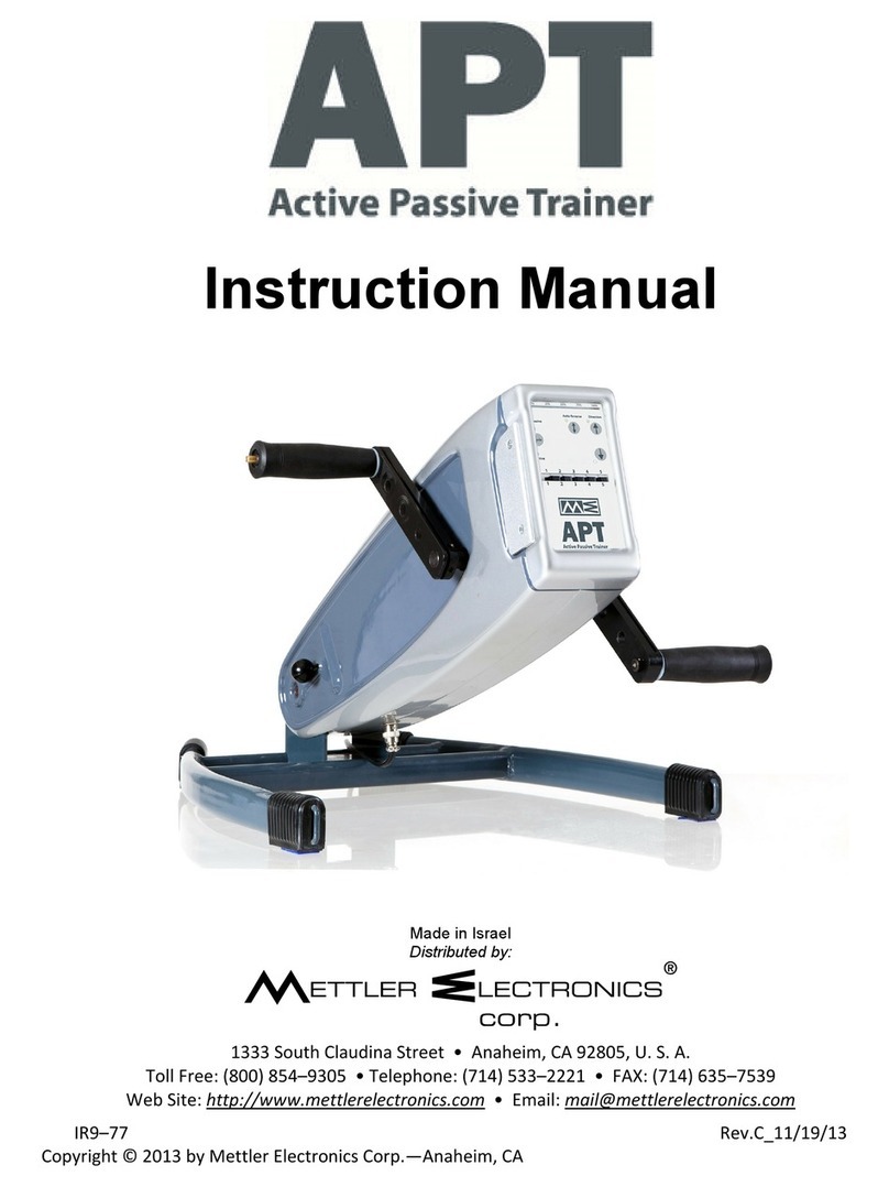
Mettler Electronics APT PLUS 8200 User manual

i
PLUS
Instruction Manual
Made in Israel
Distributed by:
1333 South Claudina Street • Anaheim, CA 92805, U. S. A.
Rev.B_8/2/13
Copyright © 2013 by Mettler Electronics Corp.—Anaheim, CA

APT PLUS – User’s Manual Rev.B_8/2/13 2

APT PLUS – User’s Manual Rev.B_8/2/13 3
Table of contents:
Page
Section A – Pre-sales Information 5
1. Introduction 5
2. Technical Data 6
3. Safety 7
4. System Components and Details 8
5. Accessories 12
Section B – User Information 13
6. Preparing the APT PLUS Hi-Lo 13
7. Installation for use – Arms exercise 14
8. Installation for use - Legs exercise 16
9. Operation instructions 19
10. Transportation and Storage 22
11. EMI – Electromagnetic Interference 23
Section C – Service Information 26
12. General Maintenance, Inspections and Storage 26
13. Disposing and Recycling 27
14. Trouble Shooting 27
15. Appendix – Exercise Parameter Values 28
NOTE: Design details may change without notice

APT PLUS – User’s Manual Rev.B_8/2/13 4

APT PLUS – User’s Manual Rev.B_8/2/13 5
SECTION A – PRE-SALES INFORMATION
1. INTRODUCTION
The APT PLUS is an electric exercise machine used for the improvement of physical abilities. The APT PLUS pro-
vides the user with a variety of exercise options and modes of operation that meet a broad range of physical needs.
A wide range of accessories are available that offer many exercise options and make the APT PLUS suitable for the
maintenance of fitness and physical well being.
The APT PLUS can be operated in either the ACTIVE mode at varying degrees of resistance or in the PASSIVE
mode at adjustable speed and torque levels. In the PASSIVE mode it is also possible to combine PASSIVE with AC-
TIVE training by using physical effort in conjunction with the electrical operation of the motor. The APT PLUS func-
tions forwards or backwards and is suitable for arm or leg exercises (upper or lower limbs). In case the user has lim-
ited strength in the arm, it is recommended to have an attendant present during exercise.
The APT PLUS’s light weight makes it portable, easy to store and convenient to use in the comfort of one’s home.
The unit is also suitable for use in healthcare institutions.
Use of the APT PLUS is recommended for the maintenance of muscle strength, flexibility, muscle tone, endurance
and general fitness for users of all ages.

APT PLUS – User’s Manual Rev.B_8/2/13 6
2. TECHNICAL DATA
APT Plus Unit
Model 8200
Weight 22 lbs.
Length 28 in. Overall
Width 18 in.
Height 6.5 in. Folded
Working voltage 24 VDC
Revolutions per minute 20 - 60 RPM
Rotation Radius 1.5, 3.0, 4.5, 6.0 in.
Exercising Positions 15°, 30°, 45°, 60°
Current Rating 4.16 A Max.
Accuracy of measurement display ±10%
Optional additional functions Remote control
Heart rate monitor
Type B equipment
Equipment not suitable for use in the presence of
flammable anaesthetic mixture with air or with oxygen
or nitrous oxide.
Continuous operation
External Power Supply
Weight 1.8 lbs.
Length 7.5 in.
Width 3.5 in.
Height 1.8 in.
Input: 100~240 V 47-63 Hz 1.25 A
Output: 24 VDC 100 W Max. 4.16 A
Class I equipment
APT Plus Hi Lo
Model 8400
Weight 86 lbs.
Base Dimensions 40 x 30 in.
Height 40 in.
Working Height from Ground Up 50 in.

APT PLUS – User’s Manual Rev.B_8/2/13 7
3. SAFETY
These safety considerations and tips will help you to operate the APT PLUS safely and prevent personal injury and
damage to your wheelchair.
1. Read this manual and all labels before operating. If you do not fully understand any part of this manual, please
contact your authorized dealer or service agent.
2. The APT PLUS should not be used in the vicinity of sensitive medical equipment.
3. Electromagnetic interference (“EMI”) can cause APT PLUS to behave erratically, which could be dangerous to
the user. For your safety and protection, it is imperative that you read the information on EMI before operating the
APT PLUS, see chapter 11.
4. EMC Warning: Radio wave sources such as radio and T.V. stations, transmitters and cellular telephones can af-
fect the performance of powered wheelchairs and mobility devices.
5. Do not operate the APT PLUS when under the influence of alcohol, medications or drugs that may impair your
safety.
6. Only the authorized dealer or service agent may perform specified set-up procedures and controller settings; pro-
gramming of the settings outside the limits as specified by the manufacturer may have adverse effects on the per-
formance.
7. Do not use the APT PLUS if it behaves abnormally or erratically, contrary to the usual performance as described
in this user manual.
8. CAUTION: Surface temperatures can increase when exposed to external sources of heat (e.g. sunlight).

APT PLUS – User’s Manual Rev.B_8/2/13 8
4. SYSTEM COMPONENTS AND DETAILS
4.1. APT PLUS unit (Figure 1)
1. Operator panel
2. Angle release knob
3. Angle securing knob
4. Crank-arm
5. Power input socket
6. Socket (not in use)
7. Height release knob (Hi-Lo only)
8. Height securing knob (Hi-Lo only)
4.2. Primary components (Figure 2):
1. Power supply unit (Provided)
2. Straight hand-grips (Optional accessory)
3. Footrests (Optional accessory)
4. Finger protection disks (Provided)
5. Securing straps (Optional accessory)

APT PLUS – User’s Manual Rev.B_8/2/13 9
When this equipment is no longer operational it must
be sent to a separate collection facility for recovery
and recycling.
CE approved Notified Body No. 0123.
Type B equipment.
Read this user manual and all labels before operating.

APT PLUS – User’s Manual Rev.B_8/2/13 10
10% 50%25% 75% 100%
The APT PLUS - Operator Panel
Figure 3
On/Off button: green indicator is lit when the APT PLUS is switched on.
Mode button: for selecting active or passive mode of operation.
Green indicator is lit when ACTIVE mode is selected by mode button.
Green indicator is lit when PASSIVE mode is selected by mode button.
Indicates actual load level as percentage of chosen load level (see 16).
Button for forward operation in the PASSIVE mode. The green indicator
is lit to indicate forward operation.
Button for backward operation in the PASSIVE mode. The green indica-
tor is lit to indicate backward operation.
Button activating Auto-Reverse function in the PASSIVE mode. In the
ACTIVE mode this button activates the constant force function. The
green indicator is lit when activated.
Button for selecting display of data, (see 10-13):
Green indicator is lit when Timer display is selected. The display will
show the time the APT PLUS has been used in the current exercise pe-
riod.
Green indicator is lit when Counter display is selected. The display will
show the total amount of revolutions of the crank arm in the current exer-
cise period.

APT PLUS – User’s Manual Rev.B_8/2/13 11
Green indicator is lit when Power display is selected. The display will
show the power during exercise in Watts – only in Active mode.
Heart rate monitor
Display for Timer, Counter and Energy.
Exercise speed level selection push buttons
+ – Increases speed level (up to 10)
- – Decreases speed level (down to 1)
Exercise load level selection push buttons
+ – Increases load level (up to 10)
- – Decreases load level (down to 1)

APT PLUS – User’s Manual Rev.B_8/2/13 12
5. ACCESSORIES
The following items are designed for use in combination with the APT PLUS.
CAUTION: The use of accessories other than these can be unsafe.
5.1 Hand grips and Footrests
# ACCESSORY USAGE DESCRIPTION FIGURE
a) Straight
Handgrips Used for most of the upper limb exercising.
b) Angled
Handgrips
Ergonomically designed, mainly for strength
exercising in the Active mode.
c) Hemi-glove
Used for securely supporting the wrist and
hand on the handgrips for users who have
little or no muscle strength.
d) Standard
Footrests Used for most of the lower limb exercising.
e) High support
for footrests
May be attached to footrests for supporting
the lower limbs of users that have little or
no muscle strength.
f) Strap
Used to secure the APT Plus to chair or
wheel chair to keep it from moving away
from patient during exercise
5.2 Optional added functions
# ACCESSORY USAGE DESCRIPTION FIGURE
a) Remote Con-
trol
Used mainly for lower limb ex-
ercising by users who have dif-
ficulty in reaching the operating
panel.
b) Pulse rate
monitor
Plugs into APT Plus and heart
beats are registered by indicator
on front panel.

APT PLUS – User’s Manual Rev.B_8/2/13 13
SECTION B – USER INFORMATION
6. PREPARING THE APT PLUS HI-LO
Figure 4 Figure 4A
6.1 Moving your APT PLUS Hi-Lo
The APT PLUS Hi-Lo can easily be moved by lifting the end of the frame and pushing the unit using its wheels,
see Figure 4.
6.2 Positioning the APT PLUS Hi-Lo
Position the APT PLUS Hi-Lo close to an electrical socket outlet. The adjustable feet on the underside keep the
APT PLUS Hi-Lo level and prevent it from sliding.
NOTE: Ensure that the APT PLUS Hi-Lo is level in order to prevent damage to the trainer or its components.
If readjustment of one of the feet is needed, open the contra nut (4A/1), turn the foot (4A/2) to the desired height
and secure the foot with the contra nut (4A/1).

APT PLUS – User’s Manual Rev.B_8/2/13 14
7. INSTALLATION FOR USE – ARMS EXERCISE
Step 1: Position the APT PLUS on a level table top close to an electrical socket outlet (Figure 5).
For the APT PLUS Hi-Lo: loosen the height securing knob (Figure 1A-8), pull the grey ring of the height re-
lease knob (Figure 1A-7) and adjust the unit to the required height. Release the grey ring and tighten the
height securing knob (Figure 1A-7).
Step 2: Loosen the angle-securing knob (Figure 5-1) and adjust the APT PLUS to the required angle. To increase
the angle, lift the body of the APT PLUS, allow it to “click” into one of the operating positions and retighten
the securing knob. To decrease the angle, pull the angle release knob (Figure 6), lower the body of the APT
PLUS, allow it to “click” into another operating position and tighten the securing knob.
CAUTION: Make sure that the minimum distance between crank arm and the table surface is approx-
imately 5 cm. / 2” (Figure 5-2).
Step 3: Connect the output connector (Figure 7-1) of the power supply (Figure 7-4) to the APT PLUS power input
socket (Figure 7-2a) while ensuring correct position of connector groove opposite the guide key of socket
(Figure 7-2b).
NOTE: The APT PLUS must be used only with an original APT PLUS Power Supply unit.

APT PLUS – User’s Manual Rev.B_8/2/13 15
Step 4: Install the finger protection discs (Fig. 8-1) by sliding them into the grooves on the outside edges of the crank
arms (Figure 8-2) in the direction shown.
NOTE: The finger protection discs are important for safe operation of the unit during hands exercise.
Step 5: Insert handgrip (Figure 9-1) in one of the four mounting holes (Figure 9-2) in each of the APT PLUS crank
arms. Installation or removal requires only a straight push or pull while simultaneously pressing on the re-
lease pin (Figure 9-3) at the end of the handle.
NOTE: The choice of mounting hole provides variable resistance levels and ranges of motion. See operation
instructions.
Figure 8 Figure 9
finger protection discs and crank handgrip and crank
Step 6: Plug the power supply mains power plug into the electrical socket outlet (Figure 5-3). To start operating,
press the button. The APT PLUS will enter the stand-by position. Then press the button. The
green ACTIVE mode indicator will light up. You may start exercising in the ACTIVE mode. For operation in-
structions, see 5.1 & 5.2.
NOTE: If the APT PLUS moves across the table during arm exercises, anti-slip pads (Figure 8-3) may re-
quire cleaning.

APT PLUS – User’s Manual Rev.B_8/2/13 16
8. INSTALLATION FOR USE – LEG EXERCISE
Step 1: Position the APT PLUS on the floor close to an electrical socket outlet (Figure 10).
Step 2: Loosen the angle-securing knob (Figure 10-1) and adjust the APT PLUS to the required angle. To increase
the angle, lift the body of the APT PLUS, allow it to “click” into one of the operating positions and retighten
the securing knob. To decrease the angle, pull the angle release knob (Figure 11), lower the body of the APT
PLUS, allow it to “click” into another operating position and tighten the securing knob.
CAUTION: Make sure that the minimum distance between crank arm and the floor surface is approx-
imately 5 cm. / 2” (Figure 10-2)
Step 3: Place a chair at the desired distance from the APT PLUS. If necessary, attach the Securing straps (Figure
10-6) between the APT PLUS base rings (Figure 10-5) and the chair legs to prevent any change in distance
between the APT PLUS and the chair during leg exercises.

APT PLUS – User’s Manual Rev.B_8/2/13 17
Step 4: Connect the power output connector (Figure 12-1) of the power supply (Figure 12-4) to the APT PLUS power
input socket (Figure 12-2a) while ensuring correct position of connector groove opposite the guide key of
socket (Figure 12-2b).
NOTE: The APT PLUS must be used only with an original APT PLUS Power Supply unit.
Step 5: Insert Footrest (Figure 13-1) in one of the four mounting holes (Figure 13-2) in each of the APT PLUS crank
arms. Installation or removal requires only a straight push or pull while simultaneously pressing on the re-
lease pin (Figure 13-3) as shown. Secure feet in place with straps fastened diagonally as shown in Figure 10.
NOTE: The choice of mounting hole provides variable resistance levels and ranges of motion. See operation
instructions.
Figure 13
Step 6: Plug the power supply mains power plug into the electrical socket outlet (Figure 10-3). The APT PLUS will
enter a stand-by position. To start operating, press the button. The APT PLUS will enter the stand-by
position. Then press the button. The green ACTIVE mode indicator will light up. You may start exercis-
ing in the ACTIVE mode. For operation instructions, see 5.1 & 5.2.
NOTE: If the APT PLUS moves across the floor during leg exercises, anti-slip pads (Figure 8-3) may require
cleaning. If possible – use the APT PLUS on a carpet or rubber mat.

APT PLUS – User’s Manual Rev.B_8/2/13 18
9. OPERATION INSTRUCTIONS
NOTE: Install APT PLUS for arms or legs exercise as described in the previous chapters.
9.1 Active mode - ISOKINETIC operation
Step 1: Insert the handgrips or footrests in one of the four mounting holes according to the radius and range of
motion required.
NOTE: As the effective crank arm length is reduced in the ACTIVE mode, the amount of effort required increases
while the range of motion decreases, and vice versa.
Step 2: To activate the active mode from the stand-by position (after the electrical power is supplied to the APT
PLUS and the button is pressed): press the button. The green ACTIVE mode indicator will
light up.
Step 3: Set the desired load level by pressing one of the selection push buttons, to increase the level or
to decrease the level.
Step 4: Rotate the APT PLUS handgrips or footrests forward or backward. Actual exercising force is displayed
as a percentage (%) on the Bar Indicator.
NOTE: In this mode, an increase in the rotation speed (RPM) will lead to an increase in the exercising force.
9.2 Active mode - CONSTANT FORCE Operation
Step 1: Press the button to activate the CONSTANT FORCE FUNCTION in the ACTIVE mode. The green
indicator will light up.
Step 2: Set the desired load level by pressing one of the selection push buttons, to increase the level or
to decrease the level.
Step 3: Rotate the APT PLUS handgrips or footrests forward or backwards. The exercising force as displayed on
the Bar Indicator will now remain constant at 50% for the selected load level, irrespective of the crank
arm rotation speed.

APT PLUS – User’s Manual Rev.B_8/2/13 19
9.3 PASSIVE mode
Step 1: Insert the handgrips or footrests in one of the four mounting holes according to the radius and range of
motion required.
NOTE: As the effective crank arm length is reduced in the PASSIVE mode, the range of movement is reduced
and the degree of resistance that the motor can overcome is increased.
Step 2: To activate the passive mode from the stand-by position (after the electrical power is supplied to the APT
PLUS and the button is pressed): press the button two times, until the green PASSIVE mode
indicator will light up. From the ACTIVE mode – press once only.
Step 3: Set the desired rotation speed by pressing one of the speed level push buttons and the desired force by
pressing one of the force load push buttons: to increase level, to decrease level.
Step 4: Hold onto the handgrips (for arm exercise) or secure both feet to the footrests (for legs exercise). Make
sure that APT PLUS is placed at a comfortable distance for exercise by turning the crank arms one com-
plete revolution.
Press the button for forward rotation.
Press the button for backward rotation.
NOTE: There will be a short delay before the APT PLUS begins to turn in the chosen direction.
Step 5: The operation force of the crank arms should rotate the arms or legs of with no effort on the part of the
user. This rotation force varies according to exercise level and crank arm mounting hole location select-
ed.
Step 6: To stop the rotation of the crank-arms and exit the PASSIVE mode, press the button. The indicators
will turn off and the APT PLUS will return to the stand-by position.

APT PLUS – User’s Manual Rev.B_8/2/13 20
9.4 COMBINED active/passive mode
Step 1: Operate the APT PLUS in the passive mode and work against the force of the motor by applying re-
sistance to the rotation of the crank arms.
Step 2: The resistance force to the rotation is displayed on the on the Bar Indicator as a percentage (%) at each
level.
Step 3: If the resistance force stops the crank arm rotation completely, the Bar Indicator reaches 100% and the
red indicator will light up. After holding this position for approximately 2 seconds, the crank arm rotation
will stop automatically.
NOTE: To restart, Press the button for forward rotation, or the button for backward rotation.
9.5 Passive mode – AUTO-REVERSE function
Step 1: Push the button to activate the AUTO-REVERSE function in the PASSIVE mode. The green indi-
cator will light up.
Step 2: Operate the APT PLUS as in usual passive or combined active/passive mode.
Step 3: When the resistance force stops the crank arm rotation completely, the Bar Indicator reaches 100% and
the red indicator will light up. After holding this position for approximately 2 seconds, the crank arm rota-
tion will stop automatically. After a short delay the DIRECTION OF ROTATION WILL BE REVERSED.
This feature also serves as an ANTI-SPASM function, stopping the motor in case of muscle spasm and
reversing the direction of rotation after a short delay.
Step 4: As long as the button indicator is lit, this function will continue to operate in the PASSIVE mode.
Table of contents
Other Mettler Electronics Fitness Equipment manuals
Popular Fitness Equipment manuals by other brands

Inflight Fitness
Inflight Fitness CT-ILPC Assembly instructions

Aqua Creek
Aqua Creek TIDAL WAVE F-TWPB-06 manual

Precor
Precor Discovery Plate Loaded Line Assembly guide

Titan Fitness
Titan Fitness NEMESIS CFNTLTNR210 Operator's manual

Pyle
Pyle SQUATZ THOR user guide

FRENCH FITNESS
FRENCH FITNESS FSR100 Assembly manual

AAT
AAT CargoMaster C120 V Original user manual

Crane
Crane BALANCE BOARD user guide

Impex
Impex CB-181 owner's manual

Insportline
Insportline R600i user manual

Merrithew Health & Fitness
Merrithew Health & Fitness STOTT PILATES Foam Roller quick start guide

Enraf Nonius
Enraf Nonius Crosswalker Instructions for use