Mettler Electronics SYS-STIM 206 User manual

Sys*Stim®206
Instruction Manual
®
1333 South Claudina Street • Anaheim, CA 92805, U. S. A.
Toll Free: (800) 854–9305 • Telephone: 1(714) 533–2221 • FAX: 1(714) 635–7539
IR6–05 Rev. E_4/4/13
Copyright © 1986, 2004 by Mettler Electronics Corp.—Anaheim, CA

Mettler Electronics Corp.— Rev. E_4/4/13
2

Sys*Stim 206 Instruction Manual— Rev. E_4/4/13
3
Table of Contents
Section Title Page
1 Introduction 5
1.1 Introduction to the Sys*Stim 206 5
1.2 Introduction to this Manual 5
1.3 Safety Precautions 6
1.4 Caution 6
1.5 Shipping Damage 6
1.6 Package Contents 7
1.7 Limited Warranty 7
2Control Descriptions and List of Abbreviations 9
2.1 Control Descriptions 9
2.2 List of Abbreviations 12
3Installation Instructions 13
4Operating Instructions 15
4.1 A Note About Electrodes 16
4.2 General Operating Instructions 16
4.3 Operating Instructions 17
5Indications, Contraindications, Precautions and
Adverse Reactions
19
5.1 Indications 19
5.2 Contraindications 19
5.3 Warnings 20
5.4 Precautions 21
5.5 Side Effects/Adverse Reactions 22
6Maintenance and Troubleshooting 23
6.1 Cleaning the Sys*Stim 206 23
6.2 Routine Maintenance 23
6.3 Troubleshooting the Sys*Stim 206 23
7 Specifications 25
7.1 General Specifications 25
7.2 Output Specifications 25
8Accessories 27
8.1 Ordering Information 27
8.2 Sys*Stim 206 Accessories 27

Mettler Electronics Corp.— Rev. E_4/4/13
4
List of Figures
No. Title Page
1.1 Sys*Stim 206 5
4.1 Front membrane panel and LED indicators 15
7.1 Narrow Pulse Illustration 25
7.2 Wide Pulse Illustration 26
7.3 AC Pulse Illustration 26

Sys*Stim 206 Instruction Manual— Rev. E_4/4/13
5
Section 1: Introduction
1.1 Introduction to the Sys*Stim 206
Thank you for purchasing the Sys*Stim 206 one-channel neuromuscular
stimulator. The microprocessor controlled Sys*Stim 206 produces
electrical stimulation currents through one channel.
There are four waveforms available—narrow, wide and AC pulses along
with continuous direct current. All pulsed waveforms are electrically
balanced with zero net charge.
There is a surge mode set at 6 seconds on and 18 seconds off at either 35
or 83 pulses per second.
The Sys*Stim 206 is portable and can be combined with any Sonicator®
therapeutic ultrasound unit for combination therapy.
Figure 1.1— Sys*Stim 206
1.2 Introduction to This Manual
Read the contents of this manual before treating patients with the
Sys*Stim 206.
This manual has been written to assist you with the safe operation of the
Sys*Stim 206. It is intended for use by the owners and operators of the
Sys*Stim 206. The goal of this manual is to direct the correct operation
and maintenance of this unit.

Mettler Electronics Corp.— Rev. E_4/4/13
6
The specifications and instructions presented in this manual are in effect
at the time of its publication. These instructions may be updated at any
time at the discretion of the manufacturer.
1.3 Safety Precautions
The Sys*Stim 206 operates with high voltages. Only qualified biomedical
technicians with training in neuromuscular stimulator service should
perform servicing of the Sys*Stim 206 or it should be returned directly to
the factory. To maximize safety during use, the unit should be plugged into
a grounded wall outlet. General safety guidelines for medical electronic
equipment should be followed.
Service may be obtained from the manufacturer by sending the Sys*Stim
206 in its original shipping container to Mettler Electronics Corp., 1333
South Claudina Street, Anaheim, CA 92805, ATTN: Service Department.
(Telephone toll free: (800) 854–9305, Email:
533–2221)
NOTE: All warranty repairs must be performed by Mettler Electronics
Corp. or by a service facility authorized by Mettler Electronics to perform
warranty repair work.
A service manual for the Sys*Stim 206 is available from Mettler Electronics
Corp. for a nominal charge.
1.4 Caution
Federal law restricts the sale of this device to, or on the order of, a
physician, dentist, veterinarian or any other practitioner licensed by law of
the state in which he practices.
Use of controls or adjustments or performance of procedures other than
those specified herein may result in hazardous exposure to electrical
energy. The electric energy delivered by this device may possibly be
lethal. Treatment should be administered only under the direct supervision
of a health care professional.
1.5 Shipping Damage
Your new Sys*Stim 206 is shipped complete in one carton. Upon receipt,
please inspect the carton and the unit for visible and hidden damage. If
you discover any damage, hold all shipping materials, including the carton,
and call the shipping agent who delivered the unit. They are responsible
for all damage in transit; therefore, all claims should be filed directly with
them. The factory will not be responsible for any damage in shipment, nor
allow any adjustments unless proper formal claim has been filed by the
receiver against the carrier.

Sys*Stim 206 Instruction Manual— Rev. E_4/4/13
7
The carton in which your new Sys*Stim 206 was received is specially
designed to protect the unit during shipping. Please retain all shipping
materials in the event that you will need to return your unit for servicing.
1.6 Package Contents
Your new Sys*Stim 206 comes complete with all the necessary
components to perform neuromuscular electrical stimulation. Below is a
list of items that are included in the shipping carton.
1. Sys*Stim 206
2. One electrode cable set, (ME 2260)
3. Four gray pin to banana adapters, (ME 2027)
4. Four (4" x 4") sponge electrodes (ME 2002),
5. One (3.5" x 7") sponge electrode (ME 2004)
6. One bifurcation cable set, 2 cables, one red and one black, pin
termination (ME 2030)
7. Two (48") electrode straps (ME 2009)
8. Mounting plate and screws (ME 1004)
9. Detachable U.L. listed, hospital–grade line cord, (ME 7293)
10. Instruction Manual
1.7 Limited Warranty
The Sys*Stim 206 neuromuscular electrical stimulator is warranted against
defects in materials and workmanship for a period of one year from date of
purchase. During the applicable warranty period Mettler Electronics Corp.
will, at its discretion, either repair or replace the Product without charge for
these types of defects.
For service under this warranty, the Product must be returned by the buyer
within the applicable warranty period to Mettler Electronics Corp.
Shipping charges to Mettler Electronics Corp. under this warranty
must be paid by the buyer. The buyer must also include a copy of the
sales receipt or other proof of the date of purchase. If the Product is
returned without proof of the date of purchase, it will be serviced as
an out–of–warranty product at Mettler Electronics Corp.'s prevailing
service rates.
Alteration, misuse, or neglect of the Product voids this warranty.
Except as specifically set forth above, Mettler Electronics Corp.
makes no warranties, express or implied, including without limitation
any implied warranty of merchantability or fitness for a particular
purpose, with respect to the Product. If any implied warranties apply
as a matter of law, they are limited in duration to one year.

Mettler Electronics Corp.— Rev. E_4/4/13
8
Mettler Electronics Corp. shall not be liable for any indirect, special,
consequential or incidental damages resulting from any defect in or
use of the Product.
Any legal action brought by the buyer relating to this warranty must be
commenced within one year from the date any claim arises and must be
brought only in the state or federal courts located in Orange County,
California.
Some states do not allow limitations on how long an implied warranty
lasts, or the exclusion or limitation of incidental or consequential damages,
so the above limitations or exclusions may not apply to the buyer. This
warranty gives the buyer specific legal rights, and the buyer may also have
other rights which vary from state to state.

Sys*Stim 206 Instruction Manual— Rev. E_4/4/13
9
Section 2—Control Descriptions
and List of Abbreviations
2.1 Control Descriptions
Mains power is controlled by an On/Off toggle switch. The
unit is off when the switch is pressed to the right and on
when pressed to the left.
00.00
Time display shows time in treatment in minutes and
seconds.
The timer keypad consists of eleven touch-type buttons
labeled 0-9 and timer bypass. Prior to starting an
operation, these buttons allow for entering the desired
treatment time from 1 to 29 minutes, or a continuous run
by depressing timer bypass. Either treatment time
remaining will be displayed on the treatment time
indicator, or elapsed time with flashing dashes when in
timer bypass mode. Bypass elapsed time is shown in
even seconds and restarts at 0:00 after each 29 minute
time period.
The “Go” button starts timer and begins the treatment by
providing the AC, pulse, or DC energy to the electrode
jack output if the intensity control is in fully
counterclockwise position (Reset) at the time the Go
switch is depressed.
The “Hold” button” halts the timer without disturbing the
remaining treatment time and stops the electrical output
when activated. The remaining treatment time will be
indicated.
Intensity is controlled by a three quarter turn adjustment
knob. This control varies the output voltage, or current, to
the patient during operation. Output increases with a
clockwise rotation, and decrease with a counterclockwise
rotation. Reset is achieved at the fully counterclockwise
position. Operation does not begin until the Intensity
control is returned to the Reset position.
This is the electrode output jack for plugging in electrode
cables. Use Mettler part number, ME 2260 to achieve best
results.

Mettler Electronics Corp.— Rev. E_4/4/13
10
000
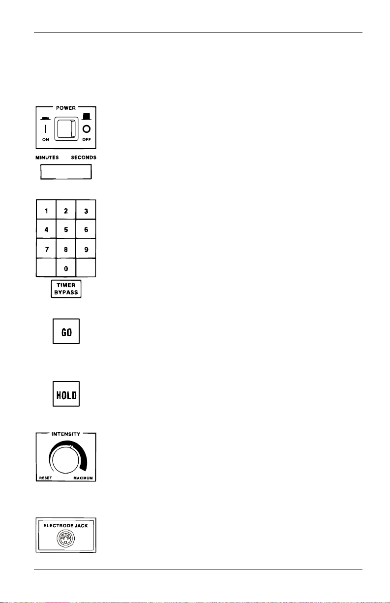
The three-digit output display shows the peak output
voltage for narrow, wide, and AC pulse modes, or the
electrical current (Milliamps) for the DC continuous mode
while treatment output is active. The meter function is
dependent upon the current mode selected prior to the
start of operation. Two green indicators, one for peak volts
and one for Milliamps specify what is being displayed by
the meter. When treatment output is inactive (Hold mode)
and when Surge is selected, the meter will display the
currently selected surge pulse frequency. (F35, for 35Hz,
or F83 for 83 Hz).
Press the “Narrow Pulse” button to enter the Narrow Pulse
mode. The green indicator to its left illuminates when
activated to show that the Narrow pulse is selected.
Selection of this current type provides electrical pulses
with current flow for 100 μs of one polarity followed by ¼
amplitude for 400 μs of reversed polarity. This results in a
net DC current flow of zero. The intensity is set by the
Intensity control. Frequency is set by the pulse frequency
control when not in Surge mode.
Press the “Wide Pulse” button to enter the Wide Pulse
mode. The green indicator to its left illuminates when
activated to show that the Wide pulse is selected. Its
shape is the same as the Narrow pulse shape except that
the pulse duration is 300 μs of one polarity followed by ¼
amplitude for 1200 μs of reversed polarity.
Press the “AC Pulse” button to enter the AC Pulse mode.
The green indicator to its left illuminates when activated to
show that the AC pulse is selected. Selection of this
current type provides electrical pulses that automatically
change current direction to achieve a net current flow of
zero. Each current cycle is 300 μs of one polarity followed
by 300 μs of the same amplitude of reversed polarity. The
intensity is set by the Intensity control. Frequency is set by
the Pulse frequency control when not in Surge mode.
Press the “DC Continuous” button to enter the DC
Continuous mode. The green indicator to its left
illuminates when activated to show that DC Continuous is
selected. Selection of this current type provides an output
current in one direction with the intensity set by the
Intensity Control up to a maximum of 30 milliamps (ma).
The frequency control is inoperative in this mode. Caution:
applications of galvanic (DC) current can produce skin
irritation. Please review contraindications.

Sys*Stim 206 Instruction Manual— Rev. E_4/4/13
11
Press the “Surge” button to enter the Surge mode. The
green indicator to its left illuminates when activated to
show that the Surge mode is selected. Selection of this
mode is in conjunction with selection of any one of the
pulse current types. The one time only initial 15-second
period of the Surge mode (after”Go” when the green pulse
frequency indicator is on) is intended for adjusting the
peak intensity to be attained during the Surge cycle. The
intensity level set during this period will not be exceeded
during the Surge cycle. At the end of this 15-second
period, the output level falls to zero and the Surge cycle
begins. The pulse current will rise linearly from 0 to a level
set by the Intensity Control (during the initial 15-second
adjustment period) in 3.06 seconds, hold at the intensity
for 5.88 seconds, and fall at a linear rate to 0 in 3.06
seconds. The output will remain at 0, or rest, for 18
seconds and repeat the cycle until the end of treatment, or
the Hold button is depressed. It is recommended that the
intensity be increased only during the initial 15-second
period described above. The green indicator next to Pulse
Frequency control is on during that period of time.
The pulse frequency in the Surge mode is displayed in the
meter when Surge is selected and output is inactive (Hold
mode). Two frequencies are available, 35Hz or 83 Hz by
depressing the button of the currently selected pulse
waveform. Each successive depression of the selected
waveform will cause the frequency to alternate between
the two frequencies. The frequency displayed (F83 or
F35) at the initiation of treatment (depressing the Go
button) will be the frequency used in treatment. The
selected frequency for the Surge mode will remain intact
until changed in the Hold mode by depressing the
currently selected waveform button or turning power off
and then on which will default to 83Hz.
Press the “Reverse Polarity” button to reverse polarity of
the treatment waveform. The indicator to its left indicates
normal polarity when Off and reverse polarity when On.
Normal polarity sets the patient output such that the red
wire (Anode) of the cable is positive with respect to the
black wire (Cathode). Reverse polarity sets the patient
output such that the red wire is negative (Cathode) with
respect to the black wire (Anode). The result is a change
of current flow direction.

Mettler Electronics Corp.— Rev. E_4/4/13
12
Frequency is controlled by a three quarter turn adjustment
knob. This control varies the repetition rate of pulses
applied to the patient during all pulse modes except when
the Surge mode is selected. It is inoperative in the DC
Continuous mode. At the fully counterclockwise position
the pulse frequency is approximately one pulse per
second. In the fully clockwise position the pulse frequency
is approximately 83 pulses per second. Frequency
increases with a clockwise rotation and decreases with a
counterclockwise rotation. A green indicator located under
the word pulse near the pulse frequency control is
illuminated when the pulse energy is present at the
electrode jack (output).
O Mains Off.
Attention, consult instruction manual.
2.2 List of Abbreviations
Hz — Hertz (pulses per second)
LED — Light Emitting Diode
μs — Microsecond (1 x 10⁻⁶ second)
mA — Milliampere (1 x 10⁻³ ampere)
S/N — Serial Number
VAC — Volts AC

Sys*Stim 206 Instruction Manual— Rev. E_4/4/13
13
Section 3—Installation
3.1 Installation Instructions
1. Plug the attached line cord into a grounded wall outlet that is rated at
120 VAC (±10%)/60Hz (220 VAC/50Hz for export models). Your
power supply must match the voltage requirements listed on the serial
number label of your device. Do not connect the Sys*Stim 206 to a
power supply rated differently than that described above.
2. The line cord comes equipped with a standard 3–prong plug. This plug
provides grounding for the Sys*Stim 206. Do not defeat its purpose by
using 3–to–2 prong adapters or any other means of attaching to a wall
outlet.
3. Plug the electrode cable (ME 2260) into the electrode jack.
4. The Sys*Stim 206 may be susceptible to interference originating from
shortwave diathermy units operating in close proximity to it. Avoid
operating the Sys*Stim 206 adjacent to and simultaneously with
operating shortwave devices.
5. Once you have verified proper functioning of your Sys*Stim 206, using
the instructions in Section 4, please register the warranty for your
Sys*Stim 206 on line at http://www.mettlerelectronics.com/product-
registration/ .

Mettler Electronics Corp.— Rev. E_4/4/13
14
Mode Indication Table
Waveform Current Function Output
Indication
Characteristics Use
AC
Pulse frequency
Peak
Volts
Pulse frequency
control, adjust
pulse repetition rate
from 1 – 83 Hz
Large
muscles or
muscle
groups
Surge
AC output will rise,
hold and fall at a
present rate when
Surge is selected.
The cycle will
continue to repeat
until Hold is
pressed or
treatment time
expires.
Polarity
Polarity is
reversible by
depressing the
Reverse Polarity
switch.
Narrow
Pulse
Pulse frequency
Peak
Volts
Same as AC. Small
muscles or
muscle
groups or
pain
management
Surge
Same as AC
except Narrow
Pulse is surged.
Polarity Same as AC.
Wide Pulse
Pulse frequency
Peak
Volts
Same as AC.
Medium
muscles or
muscle
groups
Surge
Same as AC
except Wide Pulse
is surged.
Polartiy Same as AC.
DC
Continuous Polarity Milliamps
Polarity is
reversible by
depressing the
Reverse Polarity
button.
Denervated
muscle or
iontophoresi
s

Sys*Stim 206 Instruction Manual— Rev. E_4/4/13
15
Section 4—Operating Instructions
00.00 000
Figure 4.1—Front membrane panel and LED indicators

Mettler Electronics Corp.— Rev. E_4/4/13
16
4.1 A Note about Electrodes
To ensure safe operation of the Sys*Stim 206, follow the
recommendations listed below:
1. Current is introduced to the body by means of two electrodes, one
Active (black and negative) and one Dispersive (red and positive). The
Dispersive electrode normally is three to four times larger than the
Active and acts as the exit point for the current path, whereas the
Active electrode, being smaller, has a greater current density, or
concentration, and is the entry point.
2. We strongly encourage careful maintenance of the electrode system.
This includes the lead wires as well as the pads themselves. Worn
cables and/or poor pads (or the wrong sized pads) can have a
significant impact upon treatment results.
3. When using self-adhesive electrodes, do not exceed the number of
recommended uses listed on the instructions for V Trodes or other
reusable self–adhesive electrodes.
4. Make sure that the entire surface of the electrode is contacting the
patient.
5. Do not use moist hot packs to secure electrodes.
6. To avoid skin irritation due to high current density, do not use
electrodes smaller in surface area than 2" in diameter.
7. Do not use conductive carbon electrodes with this product especially
in the DC Continuous mode.
8. Most self-adhesive electrodes are inappropriate for use with DC
Continuous stimulation and may be permanently rendered inoperable
if DC Continuous is used with them.
9. To insure efficient current conduction necessary for proper treatment,
certain preparations must be made. Any impairment to current
conduction on the patient’s skin such as an oily or dry surface, or
excessive hair coverage, should be eliminated by cleaning, wetting, or
use of sonigel couplant (supplied with each unit). Shaving may be
necessary depending upon the density of hair coverage. Failure to
provide for maximum current conduction efficiency could result in skin
irritation relating to an increase in current density at the electrode site.
10. Whenever clinically possible, utilize the largest possible pads to
reduce local increases in current density. In situations where small
pads are required, use the lowest stimulation intensity necessary to
achieve the desired clinical results.
4.2 General Operating Instructions:
Before you start.
a) Review precautions, contraindications and side
effects/adverse reactions listed in Section 5.

Sys*Stim 206 Instruction Manual— Rev. E_4/4/13
17
b) Use Mettler Electronics electrodes to ensure safe and
effective operation.
c) Verify connection of the line cord to a grounded wall
receptacle.
d) Connect the electrode cable (ME 2260) into the electrode
jack.
e) Note: Descriptions of the symbols used on controls are in
Section 2.
4.3 Operating Instructions
1. Set the Intensity control to reset (minimum).
2. Set the Pulse frequency control to Minimum.
3. Insert treatment cords into electrode pads and insert the dual cord
plug into the Sys*Stim 206 electrode jack. To assure conductivity
across the electrode-to-patient interface, saturate electrode sponges
with tap water or other conductive fluids (except when using carbon
flex Tens electrodes where the use of conductive gel is required).
4. Depress the Main power control to the On position. The following
indications should be present (if not, refer to the troubleshooting guide
at the end of this manual.):
Narrow pulse: green indicator lit.
Timer indicator: decimal point only.
Output meter: “0”
Peak volts: green indicator lit.
5. Place electrode pads over area to be treated using proper technique.
(Note: To reduce skin-to-pad resistance, strap the sponge electrode
firmly to the skin without impairing circulation.) Note: No straps are
necessary when using self-adhesive electrodes.
6. Enter the treatment time using the Treatment Time selector.
(Treatment time must be entered using two digits.)
a. For times up to 9 minutes, enter “0” followed by the second digit.
(Example: For 9 minutes, enter “0” then “9”.)
b. For 10 to 29 minutes, enter a “1” or “2” followed by the second
digit. (Example: For 15 minutes, enter a “1” then “5”.)
c. If an incorrect time is entered accidentally, or to change the
entered time, depress the Timer bypass switch (a row of dashed
lines should appear in the indicator) and reselect the desired
treatment time.
For combination ultrasound / stimulation treatment only – depress
Timer bypass to allow a straight 29-minute count up in even seconds.
The Sonicator treatment time selector is used for determining

Mettler Electronics Corp.— Rev. E_4/4/13
18
treatment time in combination treatment. However stimulation
continues until hold button is depressed on the Sys*stim 206.
7. Select the desired current mode by depressing one of four selector
keys: 1) Narrow pulse; 2) Wide pulse; 3) AC; or 5) DC Continuous. (a
green indicator light will come on next to the mode key that is
selected.)
8. The surge feature is available for AC and pulse modes only. Depress
the control once and F35 is displayed. Press the waveform button and
F83 is displayed. These codes indicate the set frequency for the
selected Surge Mode.
9. Reverse polarity is available for all modes.
10. After completing steps 1-8, depress “Go” to initiate the selected
treatment. Note: Refer to the mode/indication table for the specific
output indication display for each mode and option combination.
11. Rotate the Intensity Control clockwise to increase output to the desired
treatment level. (Adjust intensity in Surge mode only when the green
Pulse Frequency indicator shows pulses present during the first 15
seconds of initial Surge mode operation. After that you will only be
able to adjust the intensity level up during the “On” time of the Surge
cycle.)
12. Rotate the Pulse Frequency Control clockwise to increase pulse
repetition to desired rate (green indicator next to this control flashes
with every output pulse.) Note: The Pulse Frequency Control is
defeated in DC Continuous and Surge modes.
13. Treatment can be stopped at any time by pressing the Hold switch.
The output will fall to zero and the Timer will stop but hold its time
remaining. Restart treatment by rotating the Intensity Control fully
counterclockwise to reset position then pressing the Go switch.
Proceed from step 11. Note: A two-second beeper activates at the
end of treatment time except in timer bypass mode.

Sys*Stim 206 Instruction Manual— Rev. E_4/4/13
19
Section 5—Indications,
Contraindications, Precautions
and Adverse Reactions
5.1 Indications
The application of pulsating electric currents to the body via electrodes
elicits responses from nerves which conduct pain sensation and muscle
contraction information. Stimulation of sensory fibers will help block pain
while the stimulation of motor fibers will generate pulsatile contractions of
the muscle groups innervated by the nerves being stimulated.
Based on this information, some of the indications for use are as follow:
1. Symptomatic relief of chronic intractable pain, acute post traumatic
pain or acute post surgical pain. (Narrow pulse only)
2. Temporary relaxation of muscle spasm.
3. Prevention of post–surgical phlebo–thrombosis through immediate
stimulation of calf muscles.
4. Increasing local blood circulation.
5. Prevention or retardation of disuse atrophy.
6. Muscle re–education.
7. Maintaining or increasing range of motion.
8. Denervated or partially denervated muscles may be stimulated using
the pencil electrode to turn on and off the stimulus.
5.2 Contraindications
1. Application of galvanic (DC) current can produce skin irritation
leading to possible damage. (Knowledge of physiological effects of
continuous direct current is essential.)
2. Electrical neuromuscular stimulation should not be administered to
individuals who are or may be pregnant.
3. Do not stimulate a patient who has a cardiac demand pacemaker.
4. Patients with implanted electronic devices should not be subjected to
stimulation.
5. Placement of electrodes across the chest laterally or ante-
rior/posterior creates a possible hazard with cardiac patients and is
therefore not recommended. Do not use transthoracically in any
mode. Great care should be exercised in applying the electrical
stimulus current to any region of the thorax because the stimulus
current may produce cardiac arrhythmia. In patients with known heart

Mettler Electronics Corp.— Rev. E_4/4/13
20
disease, electrical stimulation should be used only after careful
physician evaluation and patient instruction.
6. Place electrodes in such a way to avoid stimulation of the carotid
sinus (neck) region.
7. Patients with arterial or venous thrombosis, or thrombophlebitis are at
risk of developing embolisms when electrical stimulation is applied
over or adjacent to the vessels containing the thrombus. If a patient
has a history of deep vein thrombosis, even many years past, the
affected area should not be stimulated.
8. Do not use over swollen, infected, or inflamed areas. Do not place
electrodes over skin eruptions.
9. Fresh fractures should not be stimulated in order to avoid unwanted
motion.
10. Do not apply stimulation transcerebrally (through the head).
11. Do not use on cancer patients.
12. Stimulation should not be applied immediately following trauma or to
tissues susceptible to hemorrhage.
13. Positioning electrodes over the neck or mouth may cause severe
spasm of the laryngeal or pharyngeal muscles. These contractions
may be strong enough to close the airway or cause difficulty in
breathing.
14. Do not apply stimulation for undiagnosed pain syndromes, until
etiology is established.
15. Do not apply electrodes directly over the eyes or inside body cavities.
16. Do not use electrical stimulation in conjunction with high frequency
surgical equipment or microwave therapy systems.
17. Denervated muscle stimulation must only be applied to the individual
extremities of the human body and in such a fashion that both
electrodes are located on the same extremity.
5.3 Warnings
1. Electrical stimulation is ineffective for pain of central origin, this
includes headache.
2. Electrical stimulation must be applied by a physician or other qualified
practitioner and should be used for only the prescribed purposes.
3. Electrical stimulation is of no curative value.
4. Electrical stimulation is a symptomatic treatment and as such
suppresses the sensation of pain, which could serve as a protective
mechanism.
5. The safety of electrical stimulators for use on children has not been
determined. Keep out of reach of children.
Table of contents
Other Mettler Electronics Fitness Equipment manuals