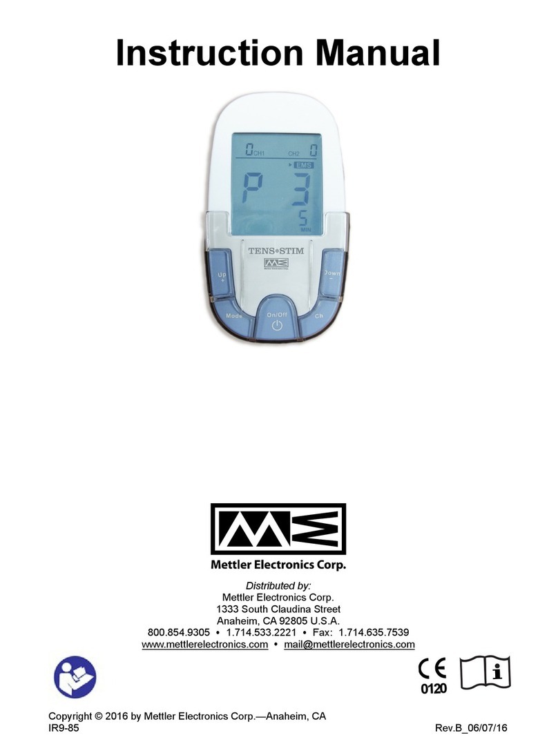
Mettler Electronics Sys Stim 240 User manual

Sys*Stim®240
Instruction Manual
1333 South Claudina Street • Anaheim, CA 92805, U. S. A.
Toll Free: (800) 854–9305 • Telephone: (714) 533–2221 • FAX: (714) 635–7539
IR9–58 Rev.I_09/23/19
Copyright © 2012 by Mettler Electronics Corp.—Anaheim, CA

Mettler Electronics Corp. — Rev.I_09/23/19
2

Sys*Stim 240 Instruction Manual — Rev.I_09/23/19
3
Table of Contents
Section Title Page
1 Introduction 5
1.1 Introduction to the Sys*Stim 240 5
1.2 Introduction to this Manual 6
1.3 Safety Precautions 6
1.4 Caution 7
1.5 Shipping Damage 7
1.6 Package Contents 8
1.7 Limited Warranty 8
2Symbol Glossary and List of Abbreviations 9
2.1 Symbol Glossary 9
2.2 Control descriptions 13
2.3 Laser and Cluster Applicators – Controls, Output aperture and Indicators 14
2.4 List of Abbreviations 15
3Installation 17
3.1 Installation Instructions 17
3.2 A Brief Operational Overview of the Sys*Stim 240 20
3.3 Optional setting 21
3.4 EMC Guidance 22
4Operating Instructions 27
4.1 A Note About Electrodes 27
4.2 General Operating Instructions 28
4.3 Quick Set-up for Electrical Stimulation 29
4.4 Set-up for Light Therapy 30
4.5 Using Preset Programs 32
4.6 Saving a Treatment Protocol 33
4.7 Interferential (IFC, 4-Pole) Procedure 34
4.8 Premodulated (IFC, 2-Pole) Procedure 35
4.9 Medium Frequency (Russian) Procedure 36
4.10 Biphasic Procedure 37
4.11 High Volt Procedure 38
4.12 Microcurrent Procedure 40
4.13 TENS, Symmetrical Biphasic Procedure 41
4.14 TENS, Asymmetrical Biphasic Procedure 42
4.15 DC Low Amplitude Procedure 43
4.16 Using the pencil electrode 43
4.17 Combination Therapy Setup Procedure 45
5Indications, Contraindications, Precautions and Adverse Reactions 47
5.1 Indications for Medium Frequency (Russian), Biphasic, High Volt Pulsed
Current (HVPC), Interferential (4P) and Premodulated (2P) waveforms
47
5.2 Additional Indications for Microcurrent, Interferential (4P), Premodulated
(2P), Biphasic and TENS waveforms
47
5.3 Indications for DC (Direct Current) Mode 47
5.4 The laser and cluster applicators of the Sys*Stim 240 emit infrared energy for: 47

Mettler Electronics Corp. — Rev.I_09/23/19
4
5.5 Contraindications for Neuromuscular Electrical Stimulation 47
5.6 Contraindications for Laser Light Therapy 48
5.7 Warnings for Neuromuscular Electrical Stimulation 48
5.8 Precautions for Laser Light Therapy 48
5.9 Precautions for Neuromuscular Electrical Stimulation 49
5.10 Side Effects/Adverse Reactions for Neuromuscular Electrical Stimulation 49
6Maintenance and Troubleshooting 51
6.1 Cleaning the Sys*Stim 240 51
6.2 Routine Maintenance 51
6.3 Troubleshooting the Sys*Stim 240 52
7 References 59
8 Specifications 61
8.1 General Specifications 61
8.2 Waveform Specifications 62
8.3 Optional Laser Performance 65
8.4 Optional Applicator Specifications 65
9Accessories 67
9.1 Ordering Information 67
9.2 Sys*Stim 240 Accessories 67
List of Figures
No. Title Page
1.1 Sys*Stim 240 5
2.1 Sys*Stim 240—Control Panel and Display 13
2.2 Laser Applicator Label Descriptions—Top 14
2.3 Laser Applicator Label Descriptions—Bottom 14
3.1 Sys*Stim 240, Bottom View Showing battery door 18
3.2 Sys*Stim 240, Bottom View—Installing the battery 19
3.3 Sys*Stim 240, Back View Showing the On/Off Switch and Power Cord and
Patient Safety Cable Connections
19
3.4 Sys*Stim 240, Side View Showing the Electrode Cable Connection 19
3.5 Sys*Stim 240, Side View Showing the Installation of the Applicator Holder 19
3.6 Sys*Stim 240, Front View Showing the Laser or Cluster Cable Connector 20
4.1 Touch Controls and Display 27
4.2 Electrode Sizes and Current Density 28
8.1 Interferential (IFC, 4-Pole) Waveform 62
8.2 Premodulated (IFC, 2-Pole) Waveform 62
8.3 Medium Frequency (Russian) Waveform 62
8.4 Biphasic Waveform 63
8.5 High Volt Waveform 63
8.6 Microcurrent Waveform 63
8.7 TENS, Sym. Waveform 64
8.8 TENS, Asym. Waveform 64

Sys*Stim 240 Instruction Manual — Rev.I_09/23/19
5
Section 1: Introduction
1.1 Introduction to the Sys*Stim 240
Thank you for purchasing the Sys*Stim 240 two-channel neuromuscular stimulator with optional
light therapy capability. The technically advanced Sys*Stim 240 provides Interferential (4 pole),
Premodulated (2 pole), Medium Frequency (Russian), Biphasic, High Volt Pulsed Galvanic,
Microcurrent, TENS-Asymmetrical Biphasic, TENS-Symmetrical Biphasic and Galvanic (Continuous
DC) waveforms.
New touch-sensitive technology has been used to make starting a treatment easy. The high-
resolution color display allows you to monitor all treatment parameters continuously. The
patented M Wheel™ provides easy navigation through all of the menus.
Figure 1.1— Sys*Stim 240
Treatment protocols complete with electrode placement guidance, allow you to quickly program
treatment parameters for your patients. There is even space to save your own special treatment
protocols for each waveform.
The Sys*Stim 240 has an optional battery pack so that you can take either electrical stimulation or
light therapy to your patient. A carrying case is also available which holds the units and all the
accessories necessary for therapy on the road.
The Sys*Stim 240 has been certified by Intertek Testing Services to meet the requirements for ETL
Listing per the following standards:
UL 60601-1 Standard for Safety Medical Electrical Equipment, Part 1: General
Requirements for Safety.
CSA C22.2.601.1 M90 Medical Electrical Equipment – Part 1 General
Requirements for Safety
IEC / EN 60601-1 Standard for Safety Medical Electrical Equipment, Part 1:
General Requirements for Safety
IEC / EN 60601-2-10 Medical Electrical Equipment Part 2: Particular
Requirements for the Safety of Nerve and Muscle Stimulators

Mettler Electronics Corp. — Rev.I_09/23/19
6
IEC / EN 60601-2-22 Medical Electrical Equipment – Part 2-22: Particular
Requirements for Safety and Essential Performance of Surgical, Cosmetic,
Therapeutic and Diagnostic Laser Equipment
IEC / EN 60825-1 Safety of Laser Products Part 1: Equipment Classification and
Requirement
IEC / EN 62471 Photobiological Safety of Lamps and Lamp Systems
In addition, the Sys*Stim 240 also meets the following standards for radio frequency emissions
and immunity:
IEC / EN 60601-1-2 Medical Electrical Equipment—Part 1-2: General
Requirements for safety—Collateral Standard Electromagnetic Compatibility
Requirements and Test
FCC 47 CFR, FCC Sub Part 18 Industrial, Scientific and Medical (ISM) Equipment
Mettler Electronics Corp. has been certified by VTT Expert Services LTD to be compliant
with EN ISO 13485:2003 and MDD 93/42/EEC Annex II requirements. In addition, Mettler is
certified by DQS Medizinprodukte GMBH to be compliant with ISO 13485:2003 (CMDCAS)
Canadian Medical Device requirements.
1.2 Introduction to This Manual
Read the contents of this manual before treating patients with the Sys*Stim 240.
This manual has been written to assist you with the safe operation of the Sys*Stim 240. It is
intended for use by the owners and operators of the Sys*Stim 240. The goal of this manual is to
direct the correct operation and maintenance of this unit.
The specifications and instructions presented in this manual are in effect at the time of its
publication. These instructions may be updated at any time at the discretion of the manufacturer.
The operating manual is required for safe use of the unit. If you lend or transfer the unit to
another party such as a facility, be sure to provide this manual with the unit.
Carefully read the Safety Precautions before operating the unit. Follow the precautions given.
To prevent injury to the operator or patient or property damage, the manual uses the
following terms and symbols to represent varying levels of danger. Make sure you understand
what these symbols mean before reading the manual.
Improper handling may result in a high risk of death or serious
injury.
Improper handling may result in a risk of death or serious injury.
Improper handling may result in injury or property damage.
Calls attention to Danger, Warning, or Caution items
This particular symbol means "Electric Shock Hazard."
Indicates an action to be avoided.
This particular symbol means: "Do Not Disassemble."

Sys*Stim 240 Instruction Manual — Rev.I_09/23/19
7
Indicates a mandatory action.
This particular symbol means "Remove the plug from the power
outlet."
1.3 Safety Precautions
The Sys*Stim 240 operates with high voltages. Qualified biomedical technicians with training in
neuromuscular stimulator and light therapy service should perform servicing of the Sys*Stim 240
or it should be returned directly to the factory. To maximize safety during use, the unit should be
plugged into a grounded wall outlet. General safety guidelines for medical electronic equipment
should be followed.
Service may be obtained from the manufacturer by sending the Sys*Stim 240 in its original
shipping container to Mettler Electronics Corp., 1333 South Claudina Street, Anaheim, CA 92805,
ATTN: Service Department. (Telephone toll free: (800) 854–9305, Alternate telephone number: 1
(714) 533–2221)
NOTE: All warranty repairs must be performed by Mettler Electronics Corp. or by a service facility
authorized by Mettler Electronics to perform warranty repair work.
A service manual for the Sys*Stim 240 is available from Mettler Electronics Corp. for a nominal
charge.
1.4 Caution
Rx only. Federal law restricts the sale of this device to, or on the order of a physician, dentist,
veterinarian or any other practitioner licensed by law of the state in which he practices.
The electric energy delivered by this device may possibly be lethal. Treatment should be
administered only under the direct supervision of a health care professional. The stimulus
delivered by this device may be sufficient to cause electrocution. Electrical current above 25 µC
must not flow through the thorax because it may cause a cardiac arrhythmia.
If you choose to use either the optional cluster or laser applicator, use the protective glasses on
both you and your patient to prevent eye exposure to infrared light.
1.5 Shipping Damage
Your new Sys*Stim 240 is shipped complete in one carton. Upon receipt, please inspect the carton
and the unit for visible and hidden damage. If you discover any damage, hold all shipping
materials, including the carton, and call the shipping agent who delivered the unit. They are
responsible for all damage in transit; therefore, all claims should be filed directly with them. The
factory will not be responsible for any damage in shipment, nor allow any adjustments unless
proper formal claim has been filed by the receiver against the carrier.
The carton in which your new Sys*Stim 240 was received is specially designed to protect the unit
during shipping. Please retain all shipping materials in the event that you will need to return
your unit for servicing. NOTE: All warranty repairs are to be performed by Mettler Electronics
Corp. or an authorized Mettler Electronics warranty repair center.

Mettler Electronics Corp. — Rev.I_09/23/19
8
1.6 Package Contents
Your new Sys*Stim 240 comes complete with all the necessary components to perform
neuromuscular electrical stimulation. Below is a list of items that are included in the shipping
carton.
1. Sys*Stim 240
2. Two electrode cable sets, (ME 2260)
3. One package V Trodes, 2" diameter (ME 2702)
4. One package V Trodes, 2.75" diameter )ME2703)
5. Two pin to banana adapters, (ME 2027)
6. One patient safety switch, (ME 2403)
7. Detachable U.L. listed, hospital–grade line cord (ME 7293)
8. Instruction Manual on a CD ROM
1.7 Limited Warranty
The Sys*Stim 240 neuromuscular electrical stimulation with optional light therapy is warranted
against defects in materials and workmanship for a period of two years from date of purchase. The
Sys*Stim 240 cluster and laser applicators are warranted against defects in materials and
workmanship for a period of one year from date of purchase. The battery is warranted against
defects in materials and workmanship for a period of 90 days from date of purchase. During the
applicable warranty period Mettler Electronics Corp. will, at its discretion, either repair or replace
the Product without charge for these types of defects.
For service under this warranty, the Product must be returned by the buyer within the applicable
warranty period to Mettler Electronics Corp. Shipping charges to Mettler Electronics Corp. under
this warranty must be paid by the buyer. The buyer must also include a copy of the sales receipt
or other proof of the date of purchase. If the Product is returned without proof of the date of
purchase, it will be serviced as an out–of–warranty product at Mettler Electronics Corp.'s
prevailing service rates.
Alteration, misuse, or neglect of the Product voids this warranty. Except as specifically set forth
above, Mettler Electronics Corp. makes no warranties, express or implied, including without
limitation any implied warranty of merchantability or fitness for a particular purpose, with
respect to the Product. If any implied warranties apply as a matter of law, they are limited in
duration to one year.
Mettler Electronics Corp. shall not be liable for any indirect, special, consequential or incidental
damages resulting from any defect in or use of the Product.
Any legal action brought by the buyer relating to this warranty must be commenced within one
year from the date any claim arises and must be brought only in the state or federal courts located
in Orange County, California.
Some states do not allow limitations on how long an implied warranty lasts, or the exclusion or
limitation of incidental or consequential damages, so the above limitations or exclusions may not
apply to the buyer. This warranty gives the buyer specific legal rights, and the buyer may also have
other rights which vary from state to state.

Sys*Stim 240 Instruction Manual — Rev.I_09/23/19
9
Section 2—Symbol Glossary, Control
Descriptions and List of Abbreviations
2.1 Symbol Glossary
Stop all treatments selector
Start or pause a treatment
Enter control used to select an item.
Channel one selector
Channel two selector
Light (laser) therapy selector
Information selector
Interferential (4-pole) symbol
Select a preset protocol
Medium Frequency (Russian)
Biphasic

Mettler Electronics Corp. — Rev.I_09/23/19
10
High Volt Pulsed Galvanic
Microcurrent
TENS-Symmetrical Biphasic
TENS-Asymmetrical Biphasic
Galvanic (Continuous DC)
Amplitude Modulation (Vector, Surge and Reciprocation)
Pulse width and frequency
Frequency Modulation
Polarity functions
Time
Output intensity
Laser applicator in use
Cluster applicator in use
No light therapy applicator installed

Sys*Stim 240 Instruction Manual — Rev.I_09/23/19
11
Enter passcode
Begin or forward (not selected)
Begin or forward (selected)
Back (not selected)
Back (selected)
Time in status bar
Output in status bar
Pencil electrode function active
Battery status
Device plugged in and running on mains power supply.
Info options
System check being conducted
AC power
Attention, consult instruction manual.
Warning symbol indicates that the device emits laser energy and that proper
precautions listed in this manual need to be taken.
Type BF Equipment—Class I

Mettler Electronics Corp. — Rev.I_09/23/19
12
Mains On.
Mains Off.
Fuse rating symbol
Patient safety switch symbol
Recycle the rechargeable lithium ion battery.
Rechargeable lithium ion battery, dispose of separately from other trash.
UL Recognized Component Mark
Tested to comply with FCC standards
CE mark on battery
ETL and C–ETL Listed

Sys*Stim 240 Instruction Manual — Rev.I_09/23/19
13
2.2 Control Descriptions
Figure 2.1— Sys*Stim 240, control panel and display
1. Back-lit LCD display
2. Stop all treatments button
3. Channel 1 selector button
4. Enter button
5. Light (Laser) selector button
6. Information selector button
7. Channel 2 selector button
8. M Wheel™ rotary control dial
9. Start / Pause treatment button

Mettler Electronics Corp. — Rev.I_09/23/19
14
2.3 Laser and Cluster Applicators – Controls, Output aperture and
Indicators
1
3
5
2
4
6
Figure 2.2— Laser Applicator Label Descriptions—Top
1. Laser Output Aperture 4. “Laser Activate” Capacitance Switch
2. Aperture Warning Label 5. Increase Output Energy (repeat dosage)
3. Laser On Indicator 6. Decrease Output Energy
Laser Warning Labels
The laser applicator has four warning labels; two of these labels are visible on figure 2.2. These
two labels are the international Laser Hazard symbol which is located on the “Laser Activate”
capacitance switch pad, and the other is the yellow Laser Aperture label which has an arrow
pointing to the laser aperture at the front of the laser applicator.
The two other labels are shown in figure 2.3 below.
1 2
Figure 2.3—Laser Applicator Label Descriptions—Bottom
1. Laser Aperture Label 2. Explanatory Label

Sys*Stim 240 Instruction Manual — Rev.I_09/23/19
15
Laser On Indicator
The green Laser On indicator illuminates when the laser is lasing. When the laser beam is turned
off after the treatment time has elapsed, the Laser On indicator will turn off.
Note: When the Sys*Stim 240 turned on, the Green Indicator will flash momentarily and you will
hear a brief beep, this is normal and is provided as a start-up lamp test.
Please Note: When there is a problem with the laser applicator, the Laser On indicator will glow
an amber color. The blue LEDs will not be illuminated, but it is possible that the laser diode will be
active and therefore eye protection is still warranted. If the amber indicator light comes on and
stays on when the capacitive switch is activated, return the laser applicator for service.
Laser Activate Capacitance Switch
The “Laser Activate” capacitance switch is located on the handle section of the laser applicator
membrane. The capacitance switch works by measuring the practitioner's body capacitance across
a sensing ‘Pad’. The ‘Pad’ is a rectangular shaped area and has the words “Laser Activate” on it. By
placing a finger or thumb over the ‘Pad’, the capacitance is increased and the switch is activated.
The advantage is that it requires no force to actuate, and therefore reduces the strain a
practitioner may experience holding down a mechanical switch for possibly long periods of time.
Increase/Decrease Output Energy Keys
The two membrane keys on the handle section of the applicator are used to increase or decrease
the dosage energy. During the laser treatment, these keys are locked out so that the dosage
cannot be accidentally increased.
2.4 List of Abbreviations
AM — Amplitude Modulation (intensity is changed over time)
CC — Constant Current
CV — Constant Voltage
FM — Frequency Modulation (frequency is changed over time)
Hz — Hertz (pulses per second)
J — Joules
J/cm² — Joules per square centimeter
LCD — Liquid crystal display
A — Microampere (1 x 10⁻⁶ ampere)
mA — Milliampere (1 x 10⁻³ ampere)
s — Microsecond (1 x 10⁻⁶ second)
ms — Millisecond (1 x 10⁻³ second)
mm:ss — Minutes and seconds in timer
bps — Bursts per second
pps — Pulses per second
s — Seconds
Ser. No. — Serial Number
V — Volts
AC — Alternating Current

Mettler Electronics Corp. — Rev.I_09/23/19
16

Sys*Stim 240 Instruction Manual — Rev.I_09/23/19
17
Section 3—Installation
3.1 Installation Instructions
1. When installing the unit, pay attention to the following:
Install the unit beyond the reach of possible water splashes.
Install the unit where it will not be adversely affected by atmospheric pressure,
temperature, humidity, sunlight, dust, ventilation, salt air, sulfur, or other such harmful
substances.
Protect the unit against instability, vibration, or impact (including during transportation).
Do not leave the unit in locations with combustible airborne materials such as combustible
anesthetic gases mixed with oxygen, nitrogen suboxide and air, or combustible disinfecting
agents or cleaning agents mixed with air.
Do not install the unit where chemical products are stored or where gases may be emitted.
2. The Sys*Stim 240 may be susceptible to interference originating from shortwave diathermy
units operating in close proximity to it. Avoid operating the Sys*Stim 240 adjacent to and
simultaneously with operating shortwave devices.
3. If you have chosen the optional battery pack, install the battery as seen in Figures 3.1 and 3.2.
4. To install the optional battery first remove the power cord. Then, remove the screws located
on the back panel of the Sys*Stim 240 on either side of the specification label using a Phillips
screw driver, Figure 3.1.
5. Place the battery into the compartment as shown in Figure 3.2. Turn the unit upside down
while installing the battery.
6. Close the battery compartment lid and reattach it by tightening the Phillips head screws.
7. Connect the line cord to the back of the Sys*Stim 240. (See Figure 3.3)
8. Plug the line cord into a grounded wall outlet that is rated at 100-240 VAC 50/60 Hz. Your
mains power supply must match the voltage requirements listed on the serial number label of
your device. Do not connect the Sys*Stim 240 to a power supply rated differently than that
described above.
9. The line cord comes equipped with a standard 3–prong plug. This plug provides grounding for
the Sys*Stim 240. Do not defeat its purpose by using 3–to–2 prong adapters or any other
means of attaching to a wall outlet.
10. If the optional battery is installed, it will begin charging as soon as the line cord is plugged into
the wall and the Sys*Stim 240 is turned on using the switch on the back of the unit. The
charging status will be displayed on the display. Full charging takes up to four hours. The unit
may be used while it is charging.
11. Plug the electrode cables (ME 2260) into the electrode cable connections as seen in Figure 3.4.
12. If you have chosen to purchase either the optional laser or cluster kit, then install the
applicator holders in Figure 3.5 on the side of the unit using the Phillips head screws included
with the holders. Plug in the applicator into the front of the device as seen in Figure 3.6 and
insert into the holder on the side of the unit. When using either the cluster or the laser

Mettler Electronics Corp. — Rev.I_09/23/19
18
applicator, you must wear the protective glasses and instruct your patient to wear the glasses
during treatment to prevent exposing the eyes to infrared energy.
13. Finally, plug the patient safety cable into the back of the unit as shown in Figure 3.3.
14. Once you have verified proper functioning of your Sys*Stim 240, using the instructions in
Section 4, please go online to www.mettlerelectronics.com to register your product.
15. The optional battery pack may only be used in the Sys*Stim 240 or Sonicator 740. Do not
attempt to use other batteries than Mettler part number ME7401. The batter is a lithium ion
battery. Additional precautions for handling the optional battery include:
• Do not store the Sys*Stim 240 for long periods with the battery installed.
• Keep the Sys*Stim 240 plugged into the mains to assure full battery charge when
needed.
• Do not ship the Sys*Stim 240 with the battery installed.
• Avoid shorting the battery
• Do not immerse in water.
• Do not disassemble or deform the battery
• Do not expose the battery to fire.
• Do not dispose of the battery in fire.
• Avoid excessive physical shock or vibration.
• Keep out of the reach of children.
• Never use a battery that appears to have suffered abuse.
• Lithium ion batteries are recyclable.
• Regulations for disposal vary for different countries. Dispose of in accordance with local
regulations.
• Batteries are shipped with between 30% and 50% rated capacity and this provides a
minimum of 90 days shelf life when stored at 25°C. If the temperature exceeds 25°C over
this time then the shelf life will be reduced and provisions should be made to recharge
the battery periodically.
• In order to prevent parasitic drain on the battery, the electronics will go into a shutdown
mode at 2.4±0.08V/parallel-cell-group. If this should happen, the battery pack will
require an initial low charge to activate the electronics prior to the implementation of the
normal charge. Any SMBus version 1.0, or higher, compatible charger is capable of
providing this initial pre-charge.
Figure 3.1— Sys*Stim 240, Bottom View
Showing battery door

Sys*Stim 240 Instruction Manual — Rev.I_09/23/19
19
Figure 3.2— Sys*Stim 240, Bottom View—
Installing the battery
Figure 3.3— Sys*Stim 240, Back View
Showing the On/Off Switch and Power Cord and Patient Safety Cable Connections
Figure 3.4— Sys*Stim 240, Side View
Showing the Electrode Cable Connection
Figure 3.5— Sys*Stim 240, Side View
Showing the Installation of the Applicator Holder

Mettler Electronics Corp. — Rev.I_09/23/19
20
Figure 3.6— Sys*Stim 240, Front View
Showing the Laser or Cluster Cable Connector
3.2 A Brief Operational Overview of the Sys*Stim 240
The Sys*Stim 240 has touch sensitive controls that include the patented M Wheel which is used to
scroll through menu selections and increase or decrease treatment time, stimulation intensity or
laser dosage. Below are listed some of the other features of the product.
1. Each menu item is color coded so that the clinician can determine
the status of a particular menu item. A white background denotes
an item that can be selected. A yellow background shows where
the curser is. A dark blue background indicates that you have
selected the item and now you can change its value. If a menu item
is grayed out, it cannot be selected or edited.
2. Press either the Channel 1 or Channel 2 key to go to the Electrical
Stimulation screen.
3. Press the Laser key to go to the Light Therapy screen.
4. Press the Info key to go to the Information menu.
5. Use the M Wheel to move through menu options or
increase/decrease parameter values. Sliding your finger clockwise
will move the cursor down or increase parameter values. Sliding
you finger counterclockwise will move the cursor up or decrease
parameter values.
6. Press the enter key to select a menu item.
Table of contents
Other Mettler Electronics Fitness Equipment manuals
Popular Fitness Equipment manuals by other brands

Tunturi
Tunturi RC20 Cross Fit Rack user manual

Vibrapower HIIT
Vibrapower HIIT ETF010C manual

Stairmaster
Stairmaster Core Health & Fitness 10G owner's manual

Huffy
Huffy 211972B owner's manual

Matrix
Matrix JOHNNY G KRANKCYCLE owner's manual

Peak Pilates
Peak Pilates High/Low Combination Chair Assembly guide