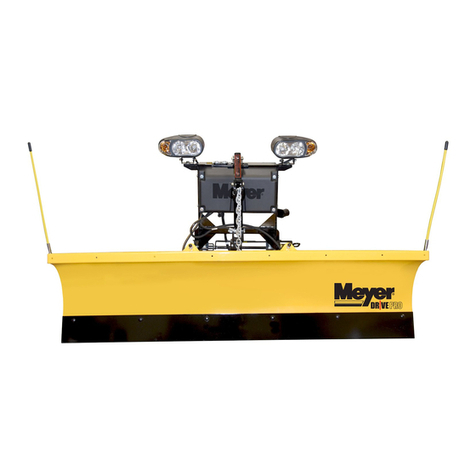
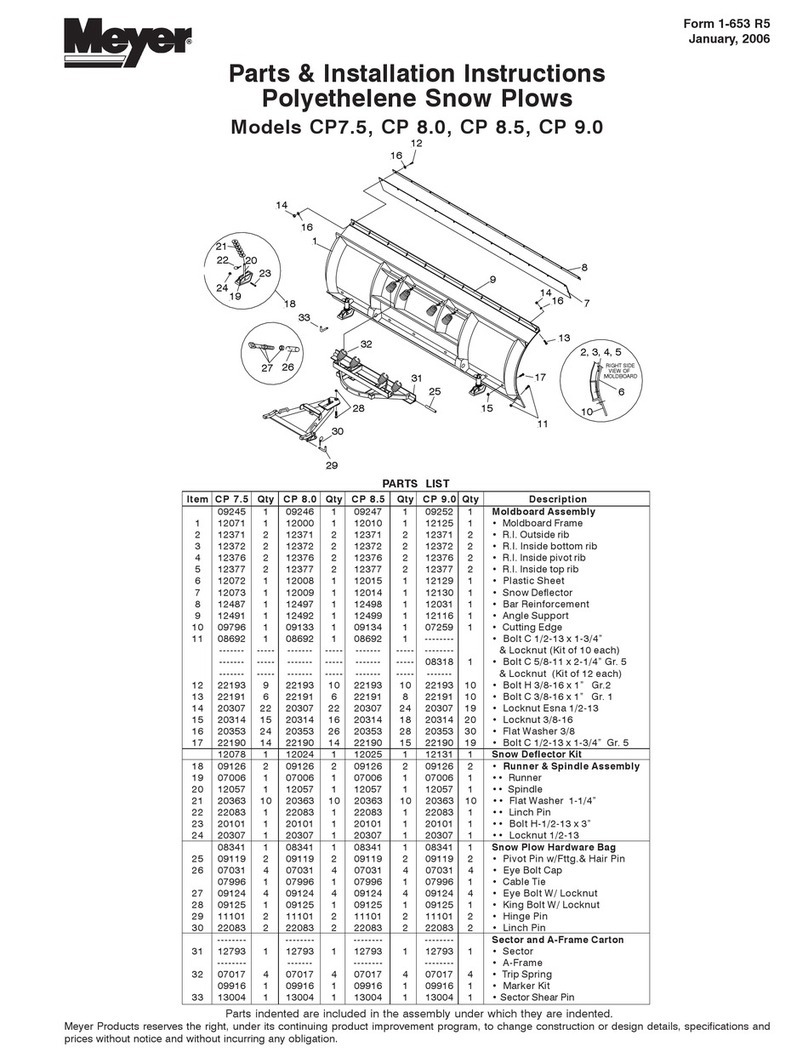
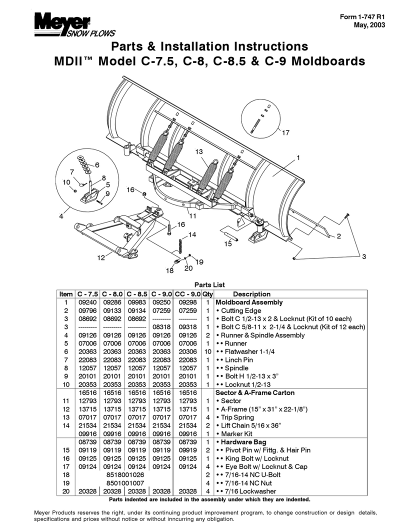
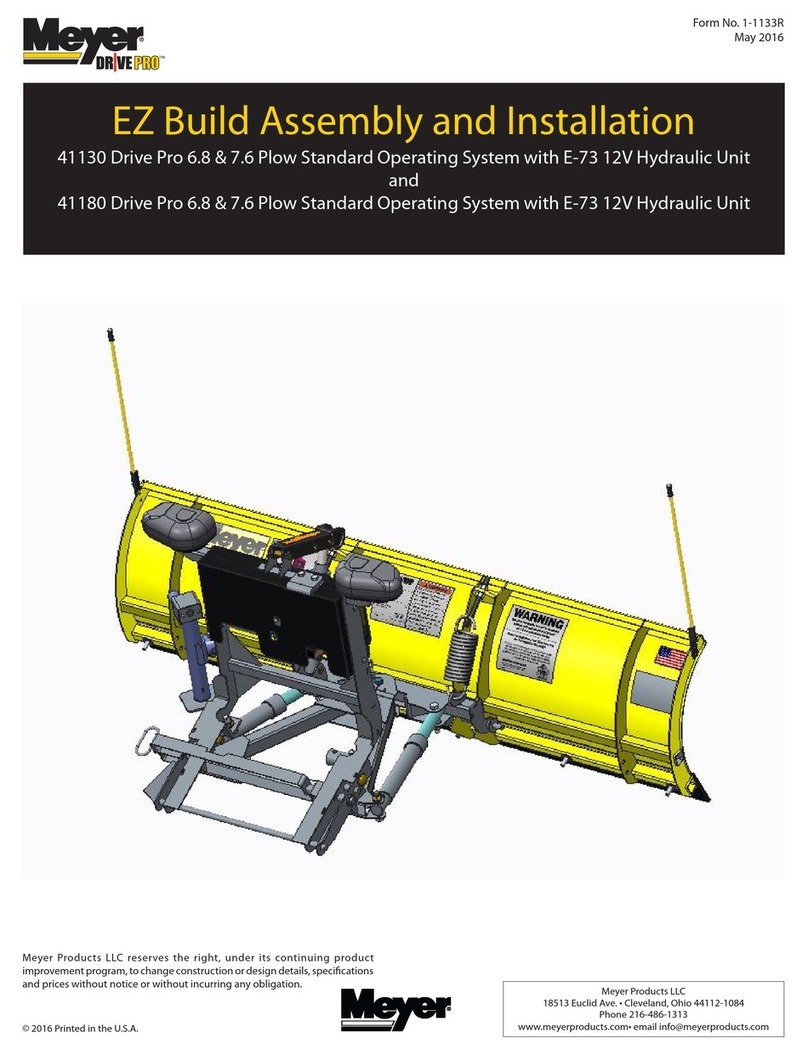
Meyer TRIMLINE Series User manual

OPERATION and
MAINTENANCE MANUAL
Insist on genuine Meyer Parts & Accessories
SNOW PLOWS

Introduction
Snow, despite the beauty it may impart to a bleak winter landscape,
poses the dual threat of inconvenience and danger. The
environmental conditions associated with snow, not to mention the
health hazards and economic loss it may impose, seriously endanger
thousands of lives annually. Business and industry suffer, and millions
of snowbelt residents may be affected by a single snowstorm.
Meyer Products Inc. has published this manual to help you get
maximum performance from your Meyer Snow Plow and
familiarize you with the features designed for efficiency and
safety; be sure you recognize and understand them. Follow
recommended operation and maintenance instructions, so when
the storm hits, your Meyer Snow Plow will be ready and you will
know how to plow like a pro. DO NOT EQUIP ANY VEHICLE WITH
A SNOW PLOW WITHOUT CONSULTING MANUFACTURER'S
RECOMMENDATIONS.
Vehicles with Meyer Snow Plows installed may be so equipped as to
meet vehicle manufacturers' specifications and recommended options
for snow plowing use. Most vehicle manufacturers insist that
vehicles which are to be used for snow plowing be equipped with
certain options and accessories, and it is so stated in vehicle
manufacturer specifications for snow plow application.
WARNING: Deployment of an air bag while using a Meyer snow
plow will not be covered under Meyer Products Inc. warranty.
We also recommend that, for optimum performance, vehicles used for
snow plowing be equipped with:
•Four-Wheel Drive
•Minimum 100 Amp Alternator or larger
•Minimum 600 C.C.A. Battery
•Mud and Snow Tires
•Increased Radiator Cooling
•Automatic Transmission
•Transmission Cooler
•Power Brakes
•Power Steering
Under the continuing Meyer Product Improvement Plan, Meyer
Products reserves the right to change design details and construction
without prior notice and without incurring any obligation.
Meyer snow plow equipment should only be used on vehicles equipped with the manufacturer's snow plow preparation packages. Snow plowing without the
original snow plow preparation package may damage your vehicle and the added weight of the equipment may impair the operation and control of the vehicle.
Snow plowing with a vehicle that the manufacturer does not recommend for that purpose may void your new vehicle warranty. If your vehicle is not originally
equipped with the snow plow preparation package, additional equipment may be necessary before snow plowing. Owners of these vehicles should consult
their truck dealers before purchase or installation of equipment. CAUTION: The installation, on any vehicle, of these parts is not a full substitute for the original
equipment snow plow preparation package.

SAFETY FIRST
Meyer Products Inc. recommends that this manual be read
cover to cover so that you, the consumer, are completely
aware of all important safety recommendations.
Table of Contents Page
Get to Know Your Meyer Snow Plow 2-7
Models of Meyer Snow Plows 8-12
Meyer MDII Snow Plow Instructions 13-16
Snow Plow Operation 17-18
General Maintenance & Adjustments 18-20
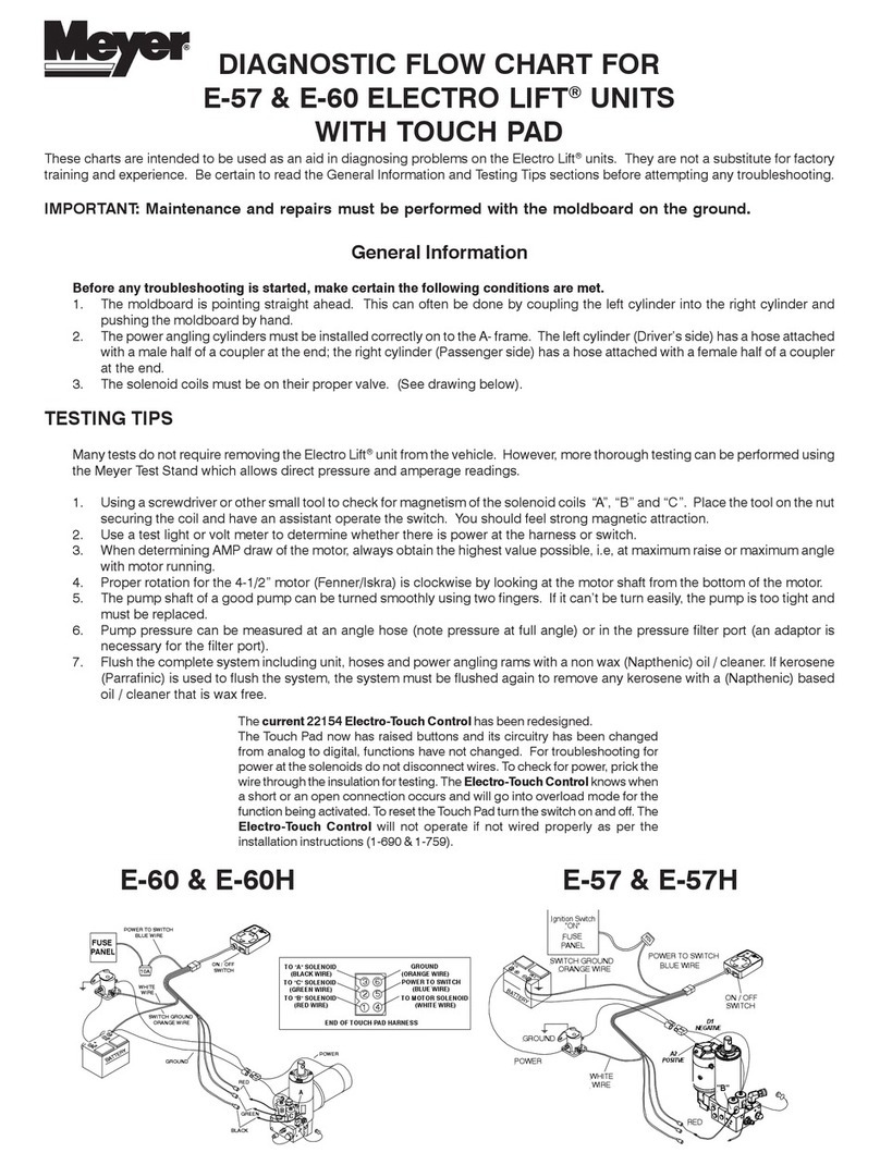
Hydraulic Power Unit Diagnosis Charts 21-23
Efficient Snow Clearance Starts with Planning 24
Keep Snow Under Control 24
Selecting Proper Size Snow Plowing Equipment 25
Hourly Snow Clearing Capacities 25
Plow with the Storm 26
Establishing Snow Clearance Plans 27
Snow Plowing Tips from the Pros 28
Snow Plowing in Open Areas 28
Parking Lots and Wide Driveways 28-29
Stacking Snow 30
Trapped and Residential Areas 30
Chemicals for Snow & Ice Control 31
Meyer Products Spreaders 32-33
Meyer Accessories 34-35
Genuine Meyer Parts 36-40
INSIST ON
GENUINE MEYER
PARTS & ACCESSORIES
• Protect your warranty
• Made to Meyer specifications
• Fit right
• Wear longer
• Perform better
• Your best value
www.meyerproducts.com
e-mail [email protected]
1

Get to know your Meyer®™ Snow Plow
2
1. Moldboard
Steel or Polyethylene sheet is bump and corrosion resistant. Built
to last.
2. Cutting Edge
Replaceable high carbon steel provides extra long operating life;
should be 1/2” above ground in plowing position. (Can be higher
when used on gravel driveways.)
3. Runners
Adjustable and replaceable runners hold cutting edge at proper
height.
4. Trip Springs
Allow moldboard to trip forward and ride over obstructions, this
protects the snow plow, vehicle, and operator.
5. Sector
High quality steel - positions moldboard straight across, or angle
right or left.
6. Pivot Pin
Pin that attaches the moldboard to the sector.
7. A-Frame
Designedtoattachthesnowplowtothevehicle,topivotmoldboard
for angle plowing, and to hold plow at proper distance in front of
vehicle.
8. Power Angling Cylinders (1-1/2” x 10”)
Hydraulically positions the moldboard straight, or to right or left.
9. Clevis Frame
Allowssnowplowassemblytobeattachedordetachedfromvehicle
in minutes.
10. MDII Lift Frame
Allowsfor fast, complete removaloffrontendhardware, snow plow
lights and hydraulic unit in one complete module.
11. Attaching Pins
Pull 4 blue pins to remove complete assembly or pull 2 yellow pins
to remove moldboard assembly.
12. Lift Arm
Dual Chain locks in position to lift snow plow.
WARNING: LIFT ARM EXTENDS BEYOND BUMPER OF
VEHICLE. TO MINIMIZE DAMAGE FROM A FRONT END
COLLISION, LIFT ARM SHOULD BE REMOVED FROM VEHICLE
WHEN SNOW PLOW IS REMOVED.
13. Meyer Snow Plow Lights
Complies with the Federal Motor Vehicle Safety Standards.
14. Electric Hydraulic Power Unit (E-60H, E-57H)
Operatessnowplowhydraulically-raises,lowers,angles,holdsand
floats moldboard in plowing position.
15. Sno-Flo® Powder Coat
Baked on finish that looks like glass, provides an extremely hard,
low friction surface that outlasts ordinary paint by a large margin.
16. Crankstand
Positions Moldboard and Lift Frame for easy attaching and
detaching.
17. Hydraulic Cover
Protects the Hydraulic Unit from the elements and also enhances
the appearance of your vehicle.

3

CRANKSTAND STORAGE
To store Crankstand on the Lift Frame slide the tube that is attached to the
side of the Crankstand over the receiver tube on the driver’s side of the Lift
Frame. Insert the chain locking pin through the vertical holes on both the
tubes. Note: Crankstand should always be fully retracted (up) and be
pinned in the vertical transport position when not in use. Receiver Tube
Cap may be placed over the driver side transport tube while the Crankstand
is in use on the A-Frame. The Receiver Tube Cap may also be switched over
to the Adjustment Tube of the A-Frame when the Crankstand is mounted to
the Lift Frame.
Storage of the Crankstand is the responsibility of the operator. The
stand can be stored on the lift frame in the retracted position to the
driver’s side transport tube or inside the vehicle cab.
HYDRAULIC COVER
Install Black Hydraulic Cover before installing the Lift Assembly to the Lift
Frame. Begin by sliding the Hydraulic Cover down over the Lift Ram. Slide
the side covering the motor carefully over the motor, do not force or stretch
the Hydraulic Cover it will fit comfortably over all parts of the Hydraulic Unit.
Feed the three coil wires (red, green and black) through the hole located on
backside of cover. Route coupler weather plugs through holes in cover where
power angling hoses enter. Snap Cover together. Caution: Care should be
taken with the installation and or removal of the Hydraulic Cover, including
partial removal when repairs are performed on the Hydraulic Lift Unit. Tearing
of the Hydraulic Cover for any reason will not be covered under the Meyer
Warranty.
ATTACHING MOLDBOARD ASSEMBLY ONLY
Attach A-Frame to Lift Frame by connecting Crankstand to the adjustment
tube in the center of the A-Frame Frame. Insert the chained locking pin all
the way through the vertical holes on both the tubes. Crank up A-Frame until
the holes on the back ears of the A-Frame are about 12" off the ground. Pull
out the Yellow Handle Pins on both sides of the Lift Frame. Twist handle
slightly to the right or left disengaging the pin. Pull truck up to the A-Frame/
Moldboard assembly aligning the A-Frame ears between the two lift frame
plates until contact is made with the Clevis Frame. Once you feel contact,
push the moldboard assembly a few inches forward, this insures proper
alignment so that the A-Frame is square to the Clevis Frame. Adjust the
Crankstand up until the front of the truck raises slightly. Rotate the Yellow
Handled Pins so that the small leg realigns with the slot, engaging the pin.
The spring loaded pin should snap into place locking the A- frame to the lift
frame. Note: If pins do not properly engage move the truck slightly forward
a few more inches and/or adjust (raise or lower) the Crankstand until pins
lock into place. If only one pin should engage, retract the stand to the full
upright position. Remove the Crankstand from the A-frame by removing the
chained locking pin. Reattach the Crankstand to the transport tube on the
driver’s side of the Lift Frame in the vertical transport position. Attach the
Lift Chain to the Lift Arm through the two hooks on the lift arm. Adjust the lift
chain at the lift arm so that there are 2-3 links of slack. This ensures that the
plow blade will lift fully and be able to follow the ground contour while plowing.
Raise the plow with the hydraulics and swing the moldboard slightly left or
right until the pin engages.
4
DETACHING THE COMPLETE ASSEMBLY
Leave control switch in lower float position and push down on the Lift Arm.
Disconnect the electrical plug and slip on weather caps over the both ends.
Attach Crankstand to the adjustment tube in the center of the A-Frame using
the chained locking pin. Caution: Crankstand must be secured at all times.
Adjust the Crankstand down until the bottom of stand touches the ground.
Pull and twist the two rear Blue Handle Pins to disengage. Next pull and
twist the two front Blue Handle Pins to disengage. If the pins do not pull
easily, adjust stand up or down slightly to remove tension on the pins until
they disengage. At this time the lift frame should be leaning forward slightly,
at rest on the top of the Crankstand. Pull truck away.
DETACHING MOLDBOARD ASSEMBLY ONLY
Leave control switch in lower float position and push down on the Lift Arm.
Disconnect hydraulic couplers and Lift Chain from Lift Arm. Attach Crankstand
to the adjustment tube in the center of the A-Frame using the chained locking
pin. Caution: Crankstand must be secured at all times. Adjust the
Crankstand down until the bottom of stand touches the ground. Pull and
twist the Yellow Handled Pins to disengage. If the pins do not pull easily,
adjust stand up or down slightly to remove tension on the pins until they
disengage. Pull truck away.
ATTACHING THE COMPLETE ASSEMBLY
Check that all four Blue Handle Pins are disengaged. Drive the truck up to
the MDII assembly centering the hood of the truck to the lift arm to assure
proper alignment with lift frame guide plates until contact is made. Once
contact is made drive forward, pushing the assembly a few inches. This
insures the A-Frame is square to the Clevis Frame for proper pin attachment.
Adjust the Crankstand up until the front of the truck raises slightly. The rear
Blue Handle Pins should now be aligned with the rear holes on the clevis
frame. Twist all Blue Handle Pins so that the small leg re-aligns with the slot,
engaging the pins. The rear spring loaded pins should snap into place. Note:
If pins do not lock immediately the A-Frame is not square to the Clevis Frame.
Move truck slightly forward and/or adjust the Crankstand up or down until
rear pins engage. Once the back pins are locked push the top of the Lift
Frame towards the truck locking the front pins to the clevis frame. Remove
the Crankstand from the A-frame by removing the chained locking pin.
Reattach the Crankstand to the transport tube on the driver’s side of the Lift
Frame in the vertical, retracted position. Caution: Crankstand must be
secured at all times. Reattach the one step electrical connection.
5

1. Moldboard
Steel or polyethylene sheet is bump and corrosion-resistant. Built
to last.
2. Cutting Edge
Replaceable, high carbon steel provides extra long operating life;
should be 1/2” above ground in plowing position. (Can be higher
when used on gravel driveways.)
3. Runners
Full-swivel adjustable and replaceable runners hold cutting edge at
proper height.
4. Trip Springs
Allow moldboard to trip forward and ride over obstructions without
losing snow load—protects snow plow, vehicle, and operator.
5. Sector/5A Pivot Bar
High quality steel—positions moldboard straight across, or angle
right or left.
6. Pivot Pin
Pin that attaches moldboard to sector.
7. A-Frame
Designed to attach snow plow to vehicle, to pivot moldboard for
angle plowing, and to hold plow at proper distance in front of
vehicle.
8. Power Angling Cylinders
Hydraulically positions the moldboard straight, or to right or left.
9. Sector-Shear Pin
Only on E-46 Electro-Lift®manual angling plows.
Self-locking pin for locking moldboard in a straight or angled
position. The sector shear pin is designed to shear under hard
impact with a curb or other obstruction, thus protecting the snow
plow and vehicle.
Get to know your Meyer®EZ Mount Snow Plow
10. Clevis Frame
Allows adjustment of the Snow Plow A-Frame attaching point
(clevis height) for transfer of power from the vehicle frame to the
snow plow. Clevis frame weather plugs (Item 17) protect receiver
tubes from dirt and moisture when lift frame (Item 12) is removed.
Note: Adjustment bolt threads should be coated with chassis
grease or anti-seize lubricant. Adjust bolts for minimum
clearance between lift frame and receiver tubes while still
allowing for ease of lift frame removal.
11. Linch Pins
Allow snow plow assembly to be attached or detached from
vehicle in minutes.
12. Tubular Lift Frame (EZ Mount®only)
Allows for fast, complete removal of front end hardware, snow
plow lights and hydraulic unit in one complete module.
13. Lift Arm
Chain locks in position to lift snow plow.
WARNING: LIFT ARM EXTENDS BEYOND BUMPER OF
VEHICLE. TO MINIMIZE DAMAGE FROM A FRONT-END
COLLISION, LIFT ARM SHOULD BE REMOVED FROM
VEHICLE WHEN SNOW PLOW IS REMOVED.
14. Meyer Nite Saber Lights
Complies with the Federal Motor Vehicle Safety Standards.
15. Electric Hydraulic Power Unit
Operates snow plow hydraulically—raises, lowers, angles, holds
and floats moldboard in plowing position.
16. Sno-Flo®Powder Coat
Baked on finish that looks like glass, provides an extremely hard,
low friction surface that outlasts ordinary paint by a large margin.
6

16
1
3
2
8
4
9
11
6
5
7
14
13 10
12
17
15
16
4
2
1387
5A
11
7
15
E-60 E-57

Models TM-6,TM-6.5
For 4x4 Down Sized Pickups
and Sport UtilityVehicles
STEEL MOLDBOARD SPECIFICATIONS
SNOW PLOW MODEL TM-6 TM-6.5
MOLDBOARD LENGTH 6' 6 1/2'
MOLDBOARD HEIGHT 23" 23"
MOLDBOARD GAUGE 14 14
VERTICAL RIBS 4 4
NO.OF TRIP SPRINGS 2 2
CUTTING EDGE 3/8" x 6" 3/8" x 6"
PLOWINGWIDTH 64" 69"
AT FULLANGLE
SECTOR - -
POWER ANGLING RAMS 1 1/2" x 10" 1 1/2" x 10"
*AVERAGE PLOW 380 lbs. 400 lbs.
WEIGHT COMPLETE
*weight is based on average depending on specific mounting
Models TMP-6.5,TMP-7
For Down Sized Pickups
and Sport UtilityVehicles
MAX POLYETHYLENE SPECIFICATIONS
SNOW PLOW MODEL TMP-6.5 TMP-7
MOLDBOARD LENGTH 6 1/2' 7'
MOLDBOARD HEIGHT 23" 23"
MOLDBOARD GAUGE 3/8" 3/8"
Polyethylene Polyethylene
VERTICAL RIBS 4 4
NO.OF TRIP SPRINGS 2 2
CUTTING EDGE 3/8" x 6" 3/8" x 6"
PLOWINGWIDTH 69" 74"
AT FULLANGLE
SECTOR - -
POWERANGLING RAMS 1 1/2" x 10" 1 1/2" x 10"
*AVERAGE PLOW 400 lbs. 424 lbs.
WEIGHT COMPLETE
*weight is based on average depending on specific mounting
TRIMLINE SERIES
8
6’, 6 1/2’, 7’, 7 1/2’ Diamond Blade
For Skid-Steer
Vehicles
STEEL MOLDBOARD SPECIFICATIONS
SNOW PLOW MODEL DTE-6 DTE-6.5 DTE-7 DTE-7.5
MOLDBOARD LENGTH 6' 6 1/2' 7' 7 1/2'
MOLDBOARD HEIGHT 26 1/2" 26 1/2" 26 1/2" 26 1/2"
MOLDBOARD GAUGE 12 12 12 12
VERTICAL RIBS 6666
NO. OF TRIP SPRINGS 4
extension
4
extension
4
extension
4
extension
CUTTING EDGE 1/2" x 6" 1/2" x 6" 1/2" x 6" 1/2" x 6"
PLOWING WIDTH 62" 68" 73" 78"
AT FULL ANGLE
SECTOR ----
POWER ANGLING RAMS
1 1/2" x 10" 1 1/2" x 10"1 1/2" x 10" 1 1/2" x 10"
*AVERAGE PLOW 529 lbs. 543 lbs. 557 lbs. 578 lbs.
WEIGHT COMPLETE
*weight is based on average depending on specific mounting

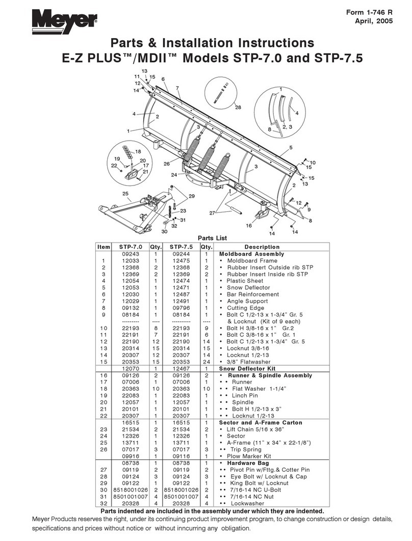
Models STP-7, STP-7.5
For 4x4 Standard Duty Pickups
and Sport Utility Vehicles
NOTE: STP-7 available with 2 trip springs.
MAX POLYETHYLENE SPECIFICATIONS
SNOW PLOW MODEL STP-7 STP-7.5
MOLDBOARD LENGTH 7' 7 1/2'
MOLDBOARD HEIGHT 27" 27"
MOLDBOARD GAUGE 3/8" 3/8"
Polyethylene Polyethylene
VERTICAL RIBS 4 4
NO. OF TRIP SPRINGS 2 3
CUTTING EDGE 3/8" x 6" 3/8" x 6"
PLOWING WIDTH 74" 79"
AT FULL ANGLE
SECTOR 11" 11"
POWER ANGLING RAMS 1 1/2" x 10" 1 1/2" x 10"
*AVERAGE PLOW 621 lbs. 660 lbs.
WEIGHT COMPLETE
*weight is based on average depending on specific mounting
Models ST-7, ST-7.5, STL-7.5
For 4x4 Standard Duty Pickups
and Sport Utility Vehicles
NOTE: ST-7 available with 2 trip springs.
STEEL MOLDBOARD SPECIFICATIONS
SNOW PLOW MODEL ST-7 ST-7.5 STL-7.5
MOLDBOARD LENGTH 7' 7 1/2' 7 1/2'
MOLDBOARD HEIGHT 25" 25" 25"
MOLDBOARD GAUGE 12 12 14
VERTICAL RIBS 4 4 4
NO. OF TRIP SPRINGS 2 3 3
CUTTING EDGE 3/8" x 6" 3/8" x 6" 3/8" x 6"
PLOWING WIDTH 74" 79" 79"
AT FULL ANGLE
SECTOR 11" 11" 11"
POWER ANGLING RAMS 1 1/2" x 10" 1 1/2" x 10" 1 1/2" x 10"
*AVERAGE PLOW 580 lbs. 606 lbs. 469 lbs.
WEIGHT COMPLETE
*weight is based on average depending on specific mounting
STANDARD SERIES
9

Models CP-7.5, CP-8, CP-8.5, CP-9.0
For 4x4 Heavy Duty 3/4 ton, 1 ton Pickups,
and 1 ton Cab Chassis
MAX POLYETHYLENE SPECIFICATIONS
SNOW PLOW MODEL CP-7.5 CP-8 CP-8.5 CP-9.0
MOLDBOARD LENGTH 7 1/2' 8' 8 1/2' 9'
MOLDBOARD HEIGHT 30" 30" 30" 30"
MOLDBOARD GAUGE 3/8" 3/8" 3/8" 3/8"
Polyethylene
VERTICAL RIBS 6 6 6 6
NO. OF TRIP SPRINGS 4 4 4 4
CUTTING EDGE 3/8" x 6" 1/2" x 6" 1/2" x 6" 1/2" x 6"
PLOWING WIDTH 79" 84" 88" 93"
AT FULL ANGLE
SECTOR 15" 15" 15" 15"
POWER ANGLING RAMS 1 1/2" x 12" 1 1/2" x 12" 1 1/2" x 12" 1-1/2" x 12"
*AVERAGE PLOW 791 lbs. 821 lbs. 840 lbs. 868 lbs.
WEIGHT COMPLETE
*weight is based on average depending on specific mounting
Models C-7.5, C-8, C-8.5, C-9
For 4x4 Heavy Duty 3/4 ton, 1 ton Pickups,
and 1 ton Cab Chassis
STEEL MOLDBOARD SPECIFICATIONS
SNOW PLOW MODEL C-7.5 C-8 C-8.5 C-9
MOLDBOARD LENGTH 7 1/2' 8' 8 1/2' 9'
MOLDBOARD HEIGHT 28" 28" 28" 28"
MOLDBOARD GAUGE 12 12 12 12
VERTICAL RIBS 6 6 6 6
NO. OF TRIP SPRINGS 4 4 4 4
CUTTING EDGE 3/8"x 6" 1/2" x 6" 1/2" x 6" 1/2" x 6"
PLOWING WIDTH 79" 84" 88" 93"
AT FULL ANGLE
SECTOR 15" 15" 15" 15"
POWER ANGLING RAMS 1 1/2" x 12" 1 1/2" x 12" 1 1/2" x 12" 1 1/2" x 12"
*AVERAGE PLOW 729 lbs. 759 lbs. 797 lbs. 802 lbs.
WEIGHT COMPLETE
*weight is based on average depending on specific mounting
HUSKY SERIES
10

Models HMP-9, HMP-10
For trucks with a G.V.W. of 16,000 to 27,000
MAX POLYETHYLENE SPECIFICATIONS
SNOW PLOW MODEL HMP-9 HMP-10
MOLDBOARD LENGTH 9' 10'
MOLDBOARD HEIGHT 36" 36"
MOLDBOARD GAUGE 3/8 POLY 3/8 POLY
VERTICAL RIBS 7 7
NO. OF TRIP SPRINGS 6 6
CUTTING EDGE 1/2" x 6" 1/2" x 6"
PLOWING WIDTH 93" 103"
AT FULL ANGLE
SECTOR 15" 15"
POWER ANGLING RAMS 2" x 12" 2" x 12"
*AVERAGE PLOW 1222 lbs. 1271 lbs.
WEIGHT COMPLETE
*weight is based on average depending on specific mounting
Models HM-9, HM-10
For trucks with a G.V.W. of 16,000 to 27,000
STEEL MOLDBOARD SPECIFICATIONS
SNOW PLOW MODEL HM-9 HM-10
MOLDBOARD LENGTH 9' 10'
MOLDBOARD HEIGHT 32" 32"
MOLDBOARD GAUGE 7 7
VERTICAL RIBS 7 7
NO. OF TRIP SPRINGS 6 6
CUTTING EDGE 1/2" x 6" 1/2" x 6"
PLOWING WIDTH 93" 103"
AT FULL ANGLE
SECTOR 15" 15"
POWER ANGLING RAMS 2" x 12" 2" x 12"
*AVERAGE PLOW 1205 lbs. 1254 lbs.
WEIGHT COMPLETE
*weight is based on average depending on specific mounting
HEAVY MUNICIPAL SERIES
11

SNOW PLOW MODEL AG-10 AGP-10 AGC-10
MOLDBOARD LENGTH 120” 120” 120”
MOLDBOARD HEIGHT 36" 36" 36"
MOLDBOARD GAUGE 10 3/8" POLY 10
VERTICAL RIBS 8 8 8
NO. OF TRIP SPRINGS 6 6 6
CUTTING EDGE 1/2" x 6" 1/2" x 6" 1/2" x 6"
PLOWING WIDTH 98" 98" 98"
AT 35°ANGLE
POWER ANGLING RAMS
2-1/2" x 11-1/2" 2-1/2" x 11-1/2" 2-1/2" x 11-1/2"
*AVERAGE PLOW 1600 lbs. 1590 lbs. 1610 lbs.
WEIGHT COMPLETE w/o options w/o options w/o options
*weight is based on average depending on specific mounting
Model HML-10
For Chevy/GMC trucks model HD3500 and 4500/5500
and Ford F-450, F-550
SPECIFICATIONS
HEAVY MUNICIPAL SERIES
12
Aggressor Models AG-10, AGP-10, AGC-10
For vehicles up to 33,000 GVW
SPECIFICATIONS
SNOW PLOW MODEL HML-10
MOLDBOARD LENGTH 10'
MOLDBOARD HEIGHT 32"
MOLDBOARD GAUGE 7
VERTICAL RIBS 7
NO. OF TRIP SPRINGS 6
CUTTING EDGE 1/2"x 6
PLOWING WIDTH 103"
AT FULL ANGLE
SECTOR 15"
POWER ANGLING RAMS 1 1/2" x 10"
1 1/2" x 12"
WEIGHT COMPLETE 1,020 lbs.
*weight is based on average depending on specific mounting
*for use with MDII and EZ Mount Systems

Meyer®™ Snow Plow Instructions
CHOICE 1: Removing MDII (Entire Mount)
13

CHOICE 1: Attaching MDII (Entire Mount)
14

CHOICE 2: Removing MDII (Moldboard Only)
15

CHOICE 2: Attaching MDII (Moldboard Only)
16

The snow plow should only be in operation when the vehicle ignition
switch and the Electro-Touch® control switch are in the "ON"
position. Care should be taken to insure that the Electro-Touch®
control switch is kept dry and free from moisture during normal
operation.
When the Electro-Touch® control switch is turned "On," yellow lights
illuminate the location of the individual touch pads for the functions of
the snow plow: (Up), (Angle Left), (Angle Right), and (Down).
Lowering of the snow plow an inch at a time is possible by tapping
the down arrow in short intervals. Holding down the down arrow will
activate a green light located in the upper left corner of the Electro-
Touch® switch. This green light indicates the snow plow is now in
the Lower/Float position. In this position the snow
plow will be able to follow the contour of the road
and the snow plow can also be angled to the left or
right. Touching the up arrow automatically cancels
the Lower/Float position.
This switch is short circuit and temperature
protected. All wire connections must be securely
plugged together. If any of these conditions exist,
the red overload LED will light. The overload LED
(red light) is located in the upper left corner below the float light of the
Electro-Touch® switch. Reset is accomplished by turning off the
ignition switch or by turning the power switch off momentarily and
then back on. If an overheating temperature condition exists, it will
17
Snow Plow Operation
Removing Moldboard Assembly
(EZ Mount)
1. Be sure moldboard is on ground! The
chain can have a small amount of tension
to help support the back of the A-Frame.
2. Remove two hinge pins from A-frame at
center hole in clevis frame.
3. On snow plows equipped with power
angling, uncouple hydraulic hoses and
interconnect hydraulic quick couplers to
prevent contamination.
4. Lower lift ram all the way and detach chain from lift arm. Reverse
the above procedure to reattach snow plow to vehicle.
5. WARNING: LIFT ARM EXTENDS BEYOND BUMPER OF
VEHICLE. TO MINIMIZE DAMAGE FROM A FRONT-END
COLLISION, LIFT ARM SHOULD BE REMOVED FROM VEHICLE
WHEN SNOW PLOW IS REMOVED.
ADJUSTING CHAIN FOR PROPER SLACK WHEN PLOWING
SNOW
1. Be sure moldboard is on ground and A-frame is reattached at
center hole in clevis frame.
2. Be sure lift piston is fully retracted.
3. Hold chain taut and choose the third link above lift arm, place that
link in lift arm locking groove. This procedure will provide the
proper amount of slack when snow plowing for the moldboard to
follow the contour of the ground. You may wish to mark that link
with paint or tape for easy identification. Due to the differences in
vehicle ride heights, extra chain links may vary in length. To
prevent the extra chain links from causing damage, remove or
secure the chain links together using an electrical tie strap.
Electro-Touch Control

be necessary to allow the unit to cool down for approximately 2
minutes. If the overload light is still illuminated after attempts to reset
the switch have failed, contact your nearest authorized Meyer
Distributor for repairs.
Note: On Model E-60 only to regulate the lower speed, locate the lower
adj. screw on Page 20, Fig. 0-3. Turn adj. screw in to slow down or out
for faster lower speed. Adjustments must be made with moldboard
on the ground. This feature is not available on model E-57.
CAUTION: When the snow plow is not in operation, the Electro
Touch® Control Switch should be in the "OFF" position.
Over-the-Road Operation
WARNING
Based on the experience of our representatives and other background,
we advise a maximum transporting speed of 40 m.p.h. or locally
regulated speeds, whichever is less, dependent upon road conditions.
The operators should, of course, maintain a safe stopping distance and
adequate passing clearance at all times.
When transporting the snow plow to avoid engine overheating, angle
the moldboard completely, carrying it as low as permitted for safety by
road and surface conditions.
General Maintenance
Meyer Products recommends this maintenance information for regular
service. Sustained heavy operation may call for more frequent
service. Snow plowing subjects a vehicle to exceptionally rugged use.
As a result, it is important to inspect and bring the snow plow and
vehicle up to maximum operating conditions. Inspection should be
made of both the vehicle and snow plow prior to the plowing
season and after each use.
IMPORTANT: Maintenance and repairs should be performed with
the moldboard on the ground.
Pre-Season Maintenance
Scheduled vehicle maintenance should be performed as
recommended by the manufacturer.
Don't forget that in addition to keeping equipment in order:
1. Keep windshield wipers, heaters and lights working.
2. Use emergency flasher lights for increased visibility and safety.
Meyer offers as standard equipment quartz halogen snow plow
lights for even brighter illumination.
3. Equip vehicles with chains where necessary.
4. Provide operators with protective clothing and with rubber gloves
for handling snow melting chemicals.
VEHICLE ELECTRICAL SYSTEM — For maximum efficiency, the
vehicle supporting the snow plow must be properly serviced. The
system should consist of at least a 70 amp/hr. battery and a 60 amp
alternator. Be sure to check regularly:
1. Battery terminals to assure they're clean and free of corrosion.
2. Electrical connections, to assure they're tight and corrosion-free.
Taping may be called for. All wires must be held clear of moving or
hot engine parts or sharp sheet metal.
3. Battery must be in top operating condition.
4. Alternator and regulator, to assure maximum electrical output.
SNOW PLOW
NOTE: Always lower moldboard to ground when vehicle is not in
use. Check the Electro-Touch® Diagnosis Chart, page 16-17, and
Post Season Maintenance, page 19, for advice on maintaining the
unit.
18
This manual suits for next models
34
Table of contents
Other Meyer Snow Blower Accessories manuals

Meyer
Meyer Drive Pro EZ Build 41130 Instruction Manual

Meyer
Meyer MDII C-7.5 User manual

Meyer
Meyer CP7.5 User manual

Meyer
Meyer Lot Pro LP-7.5 User manual

Meyer
Meyer EZ-Mount Plus User manual

Meyer
Meyer Lot Pro Light Duty User manual

Meyer
Meyer Lot Pro 41675 User manual

Meyer
Meyer 08888 User manual

Meyer
Meyer ELECTRO LIFT E-57 User manual

Meyer
Meyer Drive Pro User manual