CAUTION
• Minor electric shock may occasionally occur. Do not disassemble the
Product or touch the interior of the Product.
• Minor burns may occasionally occur. Do not touch the Product while power
is being supplied or immediately after power is turned OFF.
• Minor fires may occasionally occur. Tighten terminal screws to a torque of
9.6 in-lb (1.08 N•m) so that they do not become loose.
• Minor electric shock may occasionally occur during operation. Install the
terminal cover.
• The Product may occasionally be damaged. Do not allow any clippings or
cuttings to enter the Product during installation work.
(1) Installing/Storage Environment
1. Store the product with ambient temperature –25 to +65C (-13 to +149F), and relative humidity 25 to 90%.
2. To maintain the function of the Maintenance forecast monitor function during storage over an extended period of time,
satisfy the following conditions.
• Store the product with temperature –25 to +30C (-13 to +86F) and humidity 25 to 70% if
the storage period exceeds three months.
3. The internal parts may occasionally deteriorate and be broken due to adverse heat radiation depending on the
mounting status. The maintenance forecast monitor function may not work correctly. Do not use the product in any way
.noitcerid gnitnuom dradnats eht naht rehto
4. Use the product where the relative humidity is 25 to 85%.
5. Avoid places where the product is subjected to direct sunlight.
6. Avoid places where the product is subjected to penetration of liquid, foreign substance, or corrosive gas.
7. Avoid places subject to shock or vibration.
A device such as a contact breaker may be a vibration source. Set the Power Supply as far as possible from possible
sources of shock or vibration.
8. If the Power Supply is used in an area with excessive electronic noise, be sure to separate the Power Supply as far as
possible from the noise sources.
9. The internal parts may occasionally deteriorate and be broken due to adverse heat radiation. Do not loosen the screw
on the side face of the main body.
(2) Arrangement/Wiring
1. The light electric shock may possibly be caused. Connect the ground completely.
2.
The light ignition may possibly be caused. Ensure that input and output terminals are wired correctly.
3. Use the following material to the wire to be applied to the product for preventing from the occurrence of the smoking or
ignition caused by the abnormal load.
Recommended Wire Type:
Recommended Wire TypeTerminal
AWG14 to 20 (Cross section 0.517 to 2.081mm
2
)
AWG18 to 28 (Cross section 0.081 to 0.823mm
2
)
(wires to be stripped: 9 to 10mm)
Input
Output
Ground terminal
Alaram output terminal
AWG14 to 18 (Cross section 0.823 to 2.081mm
2
)
AWG14 or more (2.081mm
2
or more)
4. Do not apply more than 100N force to the terminal block when tightening it.
5. Be sure to remove the sheet covering the product for machining before power-on.
(3) Output Voltage Adjustment
1. The output voltage adjuster (V.ADJ) may possibly be damaged. Do not add unnecessary power.
2. Do not exceed the rated output capacity and current after adjusting the output voltage.
(4) See Specification Sheets for details.
www.mgco.jp
INSTRUCTION MANUAL
CAUTION
Indicates a potentially hazardous situation which, if not avoided, may result
in minor or moderate injury or in property damage.
1.DC output terminals ( ) are galvanically isolated from the Power input terminals ( ).
2.Overvoltage category III.
3.This equipment is for protection class 1.
4.Climatic class: 3K3
:According to EN62477-1.
Surrounding Air Temperature / Ambient Temperature : 40 C
Use in pollution degree2 environment.
Safety standards
EN
Fig. 1
MODEL
MDC6
Thank you for purchasing our product.
This manual primarily describes precautions
required in installing and wiring the power supply.
Before operating the product, read this manual
thoroughly to acquire sufficient knowledge of the
product to use it safely and correctly. Keep this
manual close at hand and use for reference during
operation.
When using MDC6-12024A-M2, read the
“MDC6 Operation Manual” together without fail.
EN
MG CO., LTD.
DC POWER
SUPPLY
• Warning Symbols
Key to Warning Symbols
Precautions for Safe Use
EN
Suitability for Use
We shall not be responsible for conformity with any standards, codes, or
regulations that apply to the combination of the products in the customer's application
or use of the product.
Take all necessary steps to determine the suitability of the product for the systems,
machines, and equipment with which it will be used.
Know and observe all prohibitions of use applicable to this product.
NEVER USE THE PRODUCTS FOR AN APPLICATION INVOLVING SERIOUS RISK
TO LIFE OR PROPERTY WITHOUT ENSURING THAT THE SYSTEM AS A WHOLE
HAS BEEN DESIGNED TO ADDRESS THE RISKS, AND THAT OUR
PRODUCT IS PROPERLY RATED AND INSTALLED FOR THE INTENDED USE
WITHIN THE OVERALL EQUIPMENT OR SYSTEM.
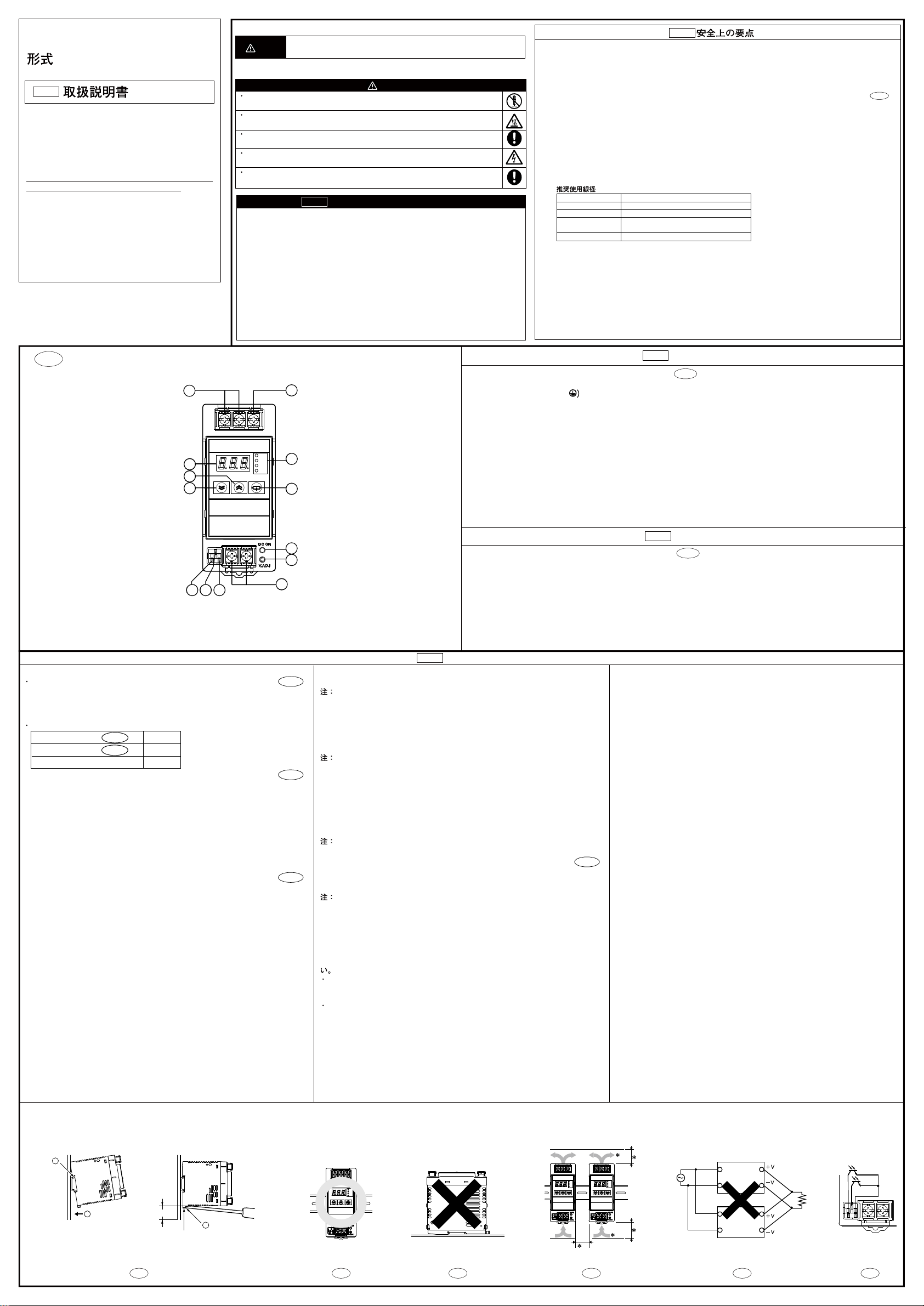
Nomenclature
Power input terminal (L),(N)
(The fuse is located on the (L) side.)
Protective Earth terminal (PE) ( )
DC output terminal (–V), (+V)
Output indicator (DC ON: green)
Output voltage adjuster (V. ADJ)
Main display unit
Operation display unit
Mode key
Up key
Down key
Alarm output terminal: Undervoltage alarm output terminals (DC LOW)
Alarm output terminal: Maintenance forecast monitor terminal (Yrs)
Common terminal for alarm output
Nomenclature
EN
Fig.1
11 12 13
12
4
5
3
6
10
9
7
8
MDC6-12024A-M2
EN
Fig.1
30 mm (1.18 inch) min.
Track stopper
B
A
C
Fig. 2
DC LOW
Yrs
Contact address
MG CO., LTD.
5-2-55, Minamitsumori, Nishinari-ku, Osaka 557-0063 JAPAN
www.mgco.jp
Precautions for Correct Use
Fig. 6
Fig. 4Fig. 3 Fig. 5
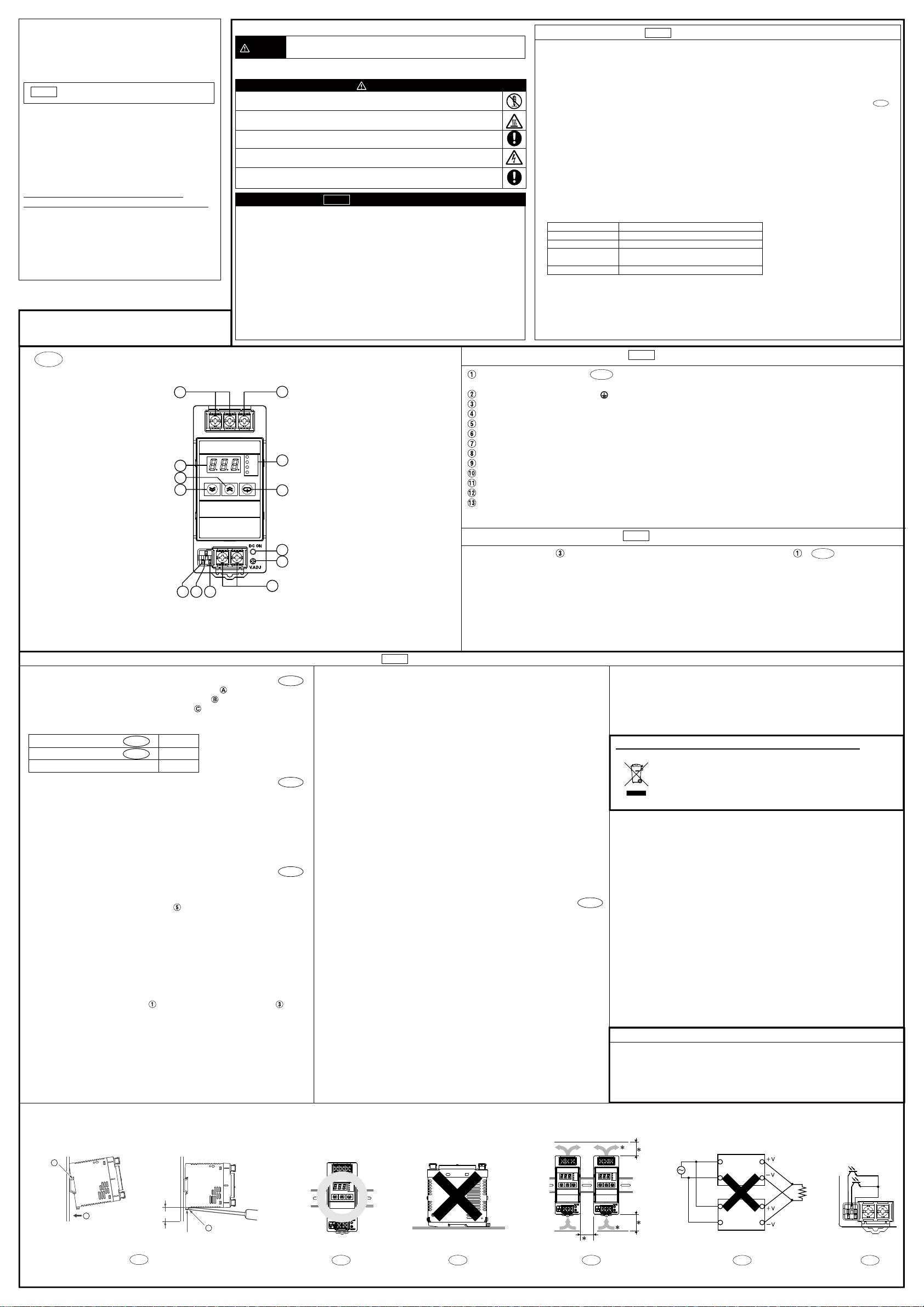
■Mounting
•DIN Track Mounting
Fig.2
To mount the power supply on a DIN track, hook portion of the power supply
onto the track and press the power supply in direction .
To dismount the power supply, pull down portion with a flat-blade screwdriver
and pull out the power supply.
•Mounting Direction
Standard Mounting
Horizontal Mounting
Others Mounting
Valid
Invalid
Invalid
Fig.3
Fig.4
•Mounting Space
Fig.5
Install the power supply so that the air flow circulates around the power supply, as
the power supply is designed to radiate heat by means of natural air flow.
*1 Direction of air circulation
*2 75 mm (2.95 inch) or more
*3 75 mm (2.95 inch) or more
*4 20 mm (0.79 inch) or more
■Rated Power Input Voltage
100 to 240 VAC Universal input
■Parallel Operation
Fig.6
The product is not designed for parallel operation.
■Output Voltage Adjustment
Default Setting: Set at the rated voltage
Adjustable Range: Adjustable with "V.ADJ " on the front
surface of the product from –10% to +15% of the rated output voltage.
Turning clockwise increases the output voltage, and turning counterclockwise
decreases the output voltage.
Notes:
1. If the output voltage is adjusted to less than 20V (factory setting), the
undervoltage alarm function may be activated.
2. Do not exceed the rated output capacity and current after adjusting the output
voltage.
■Dielectric Strength Test
Rated dielectric strength:
3000VAC between <input terminals together > and <output terminals ,⑪,
⑫ , ⑬ together > for 1 minute.
When testing, set the cutoff current for the withstand voltage test device to 20mA.
Notes:
1.Sudden switching of 3000VAC may possibly cause a voltage surge, damaging
the power supply. Increase/decrease test voltage gradually.
2.Be sure to short-circuit all the output terminals and the Alarm output terminals of
the power supply to protect the power supply from damage.
1
1
4
■Insulation Resistance Test
When testing the insulation resistance of the power supply, use a DC ohmmeter at
500VDC.
Note:
Be sure to short-circuit all the output terminals and the Alarm output terminals of the
power supply to protect the power supply from damage.
■Overload Protection
The load and the power supply are automatically protected from overcurrent damage
by this function.
Overload protection is activated if the output current rises above 105% of the rated
current.
When the output current returns within the rated range, overload protection is
automatically cleared.
Notes:
1.If the power supply has been short-circuited or supplied with an overcurrent longer
than 20 seconds, the internal parts of the power supply may occasionally be
deteriorated or damaged.
2.The internal parts may possibly be deteriorated or damaged. Do not use the
product for applications where the load causes frequent inrush current and
overload.
■Overvoltage Protection
This power supply automatically protects itself and the load from overvoltage.
Overvoltage protection is activated if the output voltage rises above approx. 130% of
the rated output voltage.
To reset the power supply, leave the power supply off for more than 3 minutes and
then turn it on again.
Note:
Be sure to clear the cause of the overvoltage, before turning on the power supply.
■Alarm Output
Fig.7
Transistor Output:Sink type (NPN type)
DC30V max. ,50mA max.
Residual voltage upon power-on: 2V or smaller.
Leakage current upon shutoff: 0.1mA or smaller.
Note:
For the undervoltage alarm function, and maintenance forecast monitor function,
refer to the “MDC6 Operation Manual”.
■In Case there is No Output Voltage
The possible cause for no output voltage may be the presence of an overload or
overvoltage condition, or may be due to the functioning of an latching protective
device. The latching protection may operate if a large amount of surge voltage such
as a lightening surge occurs while turning on the power supply.
In case there is no output voltage, please check the following points before
contacting us:
Check the Overload Protected Status:
• Check whether the load is in overload status or is short-circuited. Remove wires to
load when checking.
• Attempt to clear the overvoltage or latching protection function:
Turn the power supply off once, and leave it off for at least 3 minutes. Then turn it
on again to see if this clears the condition.
AC(L)
AC(N)
AC(L)
AC(N)
Parallel Operation
EN
MountingHorizontal
Mounting(face up)
Standard mounting
0967521-8F(SideA)
DIN Track Mounting
Fig. 7
Alarm Output
■Conformance to EU Directives
Refer to Specification Sheets and this instruction manual for details on the operating
condition for EMC-compliance.
Warning: This is a class A product. In a residential, commercial or light industrial
environment it may cause radio interference. This product is not intended to be
installed in a residential environment; in a commercial and light industrial environ-
ment with connection to the public mains supply, the user may be required to take
adequate measures to reduce interference.
CAUTION : FOR USE IN A CONTROLLED ENVIRONMENT.REFER TO MANUAL
FOR ENVIRONMENTAL CONDITIONS.
ATTENTION : POUR UTILISATION EN ATMOSPHÈRE CONTRÔLÉE.
CONSULTER LA NOTICE TECHNIQUE.
Information on waste electrical and electronic equipment
Dispose in accordance with applicable regulations.