Mi Solar Monitor-ISO SNMP User manual

1 | P a g e
Solar Monitor -ISO SNMP
Mi
Innovative Electronics for a Changing World
Solar Monitor –ISO - Remote Solar Regulator Monitor
Isolated non-contact DC current sensors –for 12V and 24V Battery systems
With Optional external relay module
INDEX
1. SYSTEM DESCRIPTION
2. SYSTEM CONNECTIONS
3. RESET TO DEFAULTS AND PASSWORDS
4. OPTIONAL 5 WAY RELAY MODULE
5. WEB PAGES
6. TFTP –REMOTE FIRMWARE UPGRADE VIA A NETWORK
7. OID TABLE
8. Mi-SNMP- MONITOR ***Freeware monitor software for Microsoft Windows
9. Physical dimensions
10. Technical Specifications

2 | P a g e
Solar Monitor -ISO SNMP
Mi
1. SYSTEM DESCRIPTION
Main Unit
Relay Board (optional)
1. SYSTEM DESCRIPTION.
The Solar monitor was designed to assist network specialist with power related
information from solar sites through Ethernet and SNMP protocol.
The system changes any existing solar regulator into a smart monitoring
device.
Solar Panel input current, Battery charge current, Load current, battery voltage and
temperature data is available via embedded web pages and SNMP V1/2C.
The Solar monitor have 3 x 75Amp isolated hall-effect non-contact current sensors
for current monitoring with no physical connection to terminals that can cause hot
connections, the cables is simply pushed through the relevant current sensor.

3 | P a g e
Solar Monitor -ISO SNMP
Mi
The unit supports SNMP V1 and SNMP V2C communication platform to be
compatible with SNMP monitoring software platforms and the free Mi-SNMP Monitor
software for Microsoft Windows.(download from
https://microinstruments.co.za/software.html)
The Solar Monitor system functions on 12V and 24V battery bank systems only
The Solar Monitor can also be easily connected to the external optional 5 way relay
module to reset or control equipment at the remote site through the Relay port.
The unit also have a potential free normally closed alarm contact input, this can
assist with attempted solar panel theft by connecting an Alarm magnetic reed switch
to the alarm input.
The system can also report both battery voltages separately as well as the total
voltage for a 24V system if the 12V centre tap wire is connected-**see system
connections page.
Solar Panel voltage not monitored !
Some Solar Regulators are common negative regulators where the positive line
from the PV input is being controlled to the charge output, other regulators are
common positive regulators where the negative line is being controlled from the PV
input to the charge output.
The problem comes in with Common positive regulators that controls the negative
input line of the solar panel, the moment the negative from the solar panel is
connected to the system ground in order to measure the solar panel input voltage, a
direct path between negative coming from the solar panel and the battery negative is
established resulting in a direct connection between the solar panel and the battery
and is actually “Bridging out” the control regulator resulting in over charging of the
batteries.
Thus we don’t measure the PV input voltage but the PV input amps only.

4 | P a g e
Solar Monitor -ISO SNMP
Mi
2. SYSTEM CONNECTIONS –(USING LOAD OUTPUT FROM REGULATOR)
SYSTEM CONNECTIONS –(NO LOAD OUTPUT USED FROM REGULATOR)

5 | P a g e
Solar Monitor -ISO SNMP
Mi
SYSTEM CONNECTIONS
The Battery wires can be a thin as the device only monitors the battery from this line
and draws very little current from this battery input line.
Current consumption in total with LAN port connected 110mA @ 12Vcdc / 55mA @
24Vdc
in order to measure the 2 individual battery voltages and the total voltage if
connected to a 24V battery system the centre tap (blue wire in drawing) have to be
connected.
**** IMPORTANT NOTE****
The Alarm input is a potential free contact input only and NO voltages should be
injected here- Permanent Damage to the unit will occur.
The 5 Way Relay board connects via 10Way IDC cable supplied with the -Relay
board
The Alarm SNMP (OID) data will change from a 0 to a 1, as soon as the Alarm input
is triggered and will stay at data 1for about 7minutes after the alarm condition was
restored , making sure polling SNMP software does not miss the alarm condition.

6 | P a g e
Solar Monitor -ISO SNMP
Mi
3. Reset to factory defaults–reset switch on the left side of the LAN port,
press the switch, keep it pressed, apply power to the unit, wait 10 sec, release
the switch, unit will be reachable on the default IP 192.168.1.2
Username: admin
Default password: admin
4. OPTIONAL 5 WAY RELAY MODULE
The 5 Relay expansion module connects to the Solar Monitor via a 10way ribbon
cable supplied with the relay module, Relay’s is rated at 10Amps 220Vac.
Relay 1,2,3 can only be toggled to activate for 10sec then return to the off position
again and is used to reset devices.
Relay 4 and 5 can be controlled to the ON or OFF position by the user and will keep
the selected position until changed by the user.
The status of all 5 relays is displayed on the home page of the unit by means of
green dots.
In the “Relay” control page the user can assign names to the relays to help
remember what is connected to the relays at the remote site.

7 | P a g e
Solar Monitor -ISO SNMP
Mi
4. WEB PAGES
HOME PAGE
The Stack version is displayed, the build date of the firmware programmed on to the
device, the units serial number as well as the model number.
A visual indication of the status of Relays 5 to 1 is given and indicated by a green dot
if the relay is active (powered)
A “module heartbeat” indication by a yellow dot flashes once per second as the
software runs through the TCPIP applications.
Alarm –ON/OFF is displayed
Left hand menu will navigate to different applications on the unit.
Home and Status page viewable without password
Password protected : Relay control page , Network page and SNMP
page
8 | P a g e
Solar Monitor -ISO SNMP
Mi
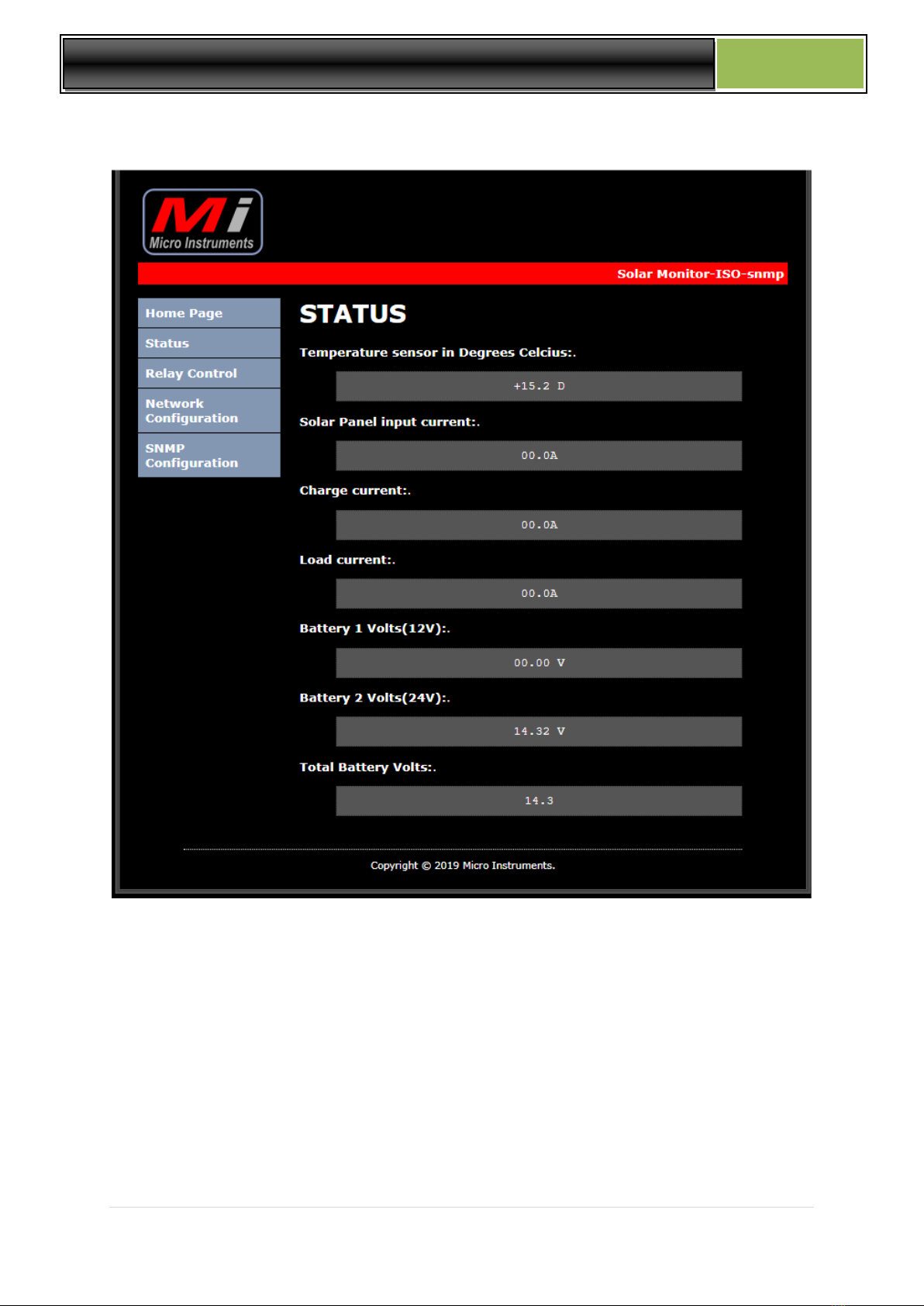
STATUS PAGE
Temperature sensor is displayed in degrees Celsius.
Solar panel input current
Charge current
Load current
Battery 1 voltage
Battery 2 voltage (24V system )
Total battery voltage

9 | P a g e
Solar Monitor -ISO SNMP
Mi
RELAY CONTROL PAGE
Admin and admin or admin and user defined password to access
Relay 4 and 5 can be controlled to the on/off status and will keep their positions,
Relay 1 to 3 can only be toggled for 10 second periods and is typically used to reset
radios or routers without logging yourself out completely from the remote site after a
relay was accidently switched , relay 1 to 3 will return automatically after 10 seconds
to the off position. Names can be assigned to relays to help the user remember what
is connected to the relays in the field.
Relays can also be activated via SNMP SET Commands over Ethernet.

10 | P a g e
Solar Monitor -ISO SNMP
Mi
SNMP CONFIG PAGE
Configure read and write communities
This can usually be left unaltered.
NETWORK CONFIGURATION PAGE
MAC address is displayed and cannot be changed / Setup IP address, Gateway and
Subnet Mask and user password
After the configuration was saved the “ Reboot in Progress” page will load
The unit will reboot and configure itself and should be live in about 5 seconds

11 | P a g e
Solar Monitor -ISO SNMP
Mi
6. TFTP Boot-loader
The Solar Monitor supports remote software upgrade over the network via
TFTP (Trivial file transfer protocol)
Should there be a firmware update or the user wants to make specific
changes to the units and we have changed the software accordingly to the
customer needs the software can be remotely upgraded over the network.
7. OID TABLE and MI-SNMP Manager software
OID table / number of services = 11
1.3.6.1.4.1.45501.1.3.1.0 = Relay 4 status (integer) 0 off / 1 on
1.3.6.1.4.1.45501.1.3.2.0 = Relay 5 status (integer) 0 off/1 on
1.3.6.1.4.1.45501.1.3.3.0 = Total Battery volts
1.3.6.1.4.1.45501.1.3.4.0 = Battery Charge Amps
1.3.6.1.4.1.45501.1.3.5.0 = Load amps
1.3.6.1.4.1.45501.1.3.6.0 = NOT USED
1.3.6.1.4.1.45501.1.3.7.0 = Temperature
1.3.6.1.4.1.45501.1.3.8.0 = Alarm status 0 off / 1 on
1.3.6.1.4.1.45501.1.3.9.0 = **Reserved / not used
1.3.6.1.4.1.45501.1.3.10.0 = Battery 1 (12V) value
1.3.6.1.4.1.45501.1.3.11.0 = Battery 2 (24v) value
1.3.6.1.4.1.45501.1.3.12.0 = Solar panel input Amps

12 | P a g e
Solar Monitor -ISO SNMP
Mi
8. MI SNMP Monitor software for Microsoft Windows
Mi SNMP Monitor is a FREE to download standalone Microsoft
Windows SNMP (simple Network Management Protocol) software
application to monitor all Remote power monitoring products
manufactured by Micro Instruments. It will also be future compatible with
all new products supporting SNMP.
Features:
Plug and Play setup –Quick and easy setup of Mi remote monitoring devices
Can add 3rd party devices to ping the equipment to indicate online / offline
status
Graphing –each device added will have its own graphical presentation of all
measured data and is unit specific.
Email alerts –Multiple email addresses can be added to the system for all alarm
notifications, units going offline and online etc. via email
Import and Export –Easily import and export all devices & application settings for
easy restore of all information.
Mi SNMP Monitor can be downloaded FREE from
https://microinstruments.co.za/software.html as a fully functional SNMP monitor
application for windows. The software package monitors all Mi remote power
monitors and also include a ping feature for other devices on the network

13 | P a g e
Solar Monitor -ISO SNMP
Mi
9. Physical Dimensions
Solar Monitor 0.500 Kg L = 163mm / W = 58mm / H = 30mm
Relay module 0.570 Kg L = 154mm / W = 55mm / H = 29mm
10. Technical Specifications
Supply Voltage :
12Vdc to 24Vdc battery systems maximum
Current consumption
with LAN port active:
110mA @ 12Vdc / 50mA @ 24Vdc
Current sensors on Charge, Load and Solar panel
75 Amp isolated non-invasive current sensors
9mm OD cables max –current sensors accept 9mm cable max
Alarm:
Potential free alarm contact input ! –no voltage injection on the
terminal
Relay I/o:
10way IDC connector / Relay module supplied with cable
Temperature sensor:
Internal / -10 to +140deg C
Enclosure:
Non waterproof
LAN Port speed:
10Mb/s
Table of contents
Other Mi Measuring Instrument manuals


