manuals.online logo
Brands
  1. Home
  2. •
  3. Brands
  4. •
  5. Nikon
  6. •
  7. Measuring Instrument
  8. •
  9. Nikon NR-5500 Operating instructions

Nikon NR-5500 Operating instructions

Other Nikon Measuring Instrument manuals
Nikon Monarch 7iVR User manual

Nikon

Nikon Monarch 7iVR User manual

Nikon PROSTAFF 1000 User manual

Nikon

Nikon PROSTAFF 1000 User manual

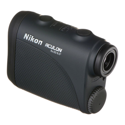
Nikon Aculon User manual

Nikon

Nikon Aculon User manual

Nikon NPL-632 User manual

Nikon

Nikon NPL-632 User manual

Nikon LASER 550A S User manual

Nikon

Nikon LASER 550A S User manual

Nikon ProStaff LASER 440 User manual

Nikon

Nikon ProStaff LASER 440 User manual

Nikon Coolshot 40i User manual

Nikon

Nikon Coolshot 40i User manual

Nikon DTM-350 User manual

Nikon

Nikon DTM-350 User manual

Nikon PROSTAFF 3i User manual

Nikon

Nikon PROSTAFF 3i User manual

Nikon Callaway iQ User manual

Nikon

Nikon Callaway iQ User manual

Nikon Coolshot 40i User manual

Nikon

Nikon Coolshot 40i User manual

Nikon Forestry Pro User manual

Nikon

Nikon Forestry Pro User manual

Nikon Forestry Pro II User manual

Nikon

Nikon Forestry Pro II User manual

Nikon MONARCH 2000 User manual

Nikon

Nikon MONARCH 2000 User manual

Nikon NPL-302 Series User manual

Nikon

Nikon NPL-302 Series User manual

Nikon ARROW ID 3000 User manual

Nikon

Nikon ARROW ID 3000 User manual

Nikon 8431 - Monarch - Dot User manual

Nikon

Nikon 8431 - Monarch - Dot User manual

Nikon Black Range X 4K User manual

Nikon

Nikon Black Range X 4K User manual

Nikon CoolShot 80 i VR User manual

Nikon

Nikon CoolShot 80 i VR User manual

Nikon Total Station DTM-322 User manual

Nikon

Nikon Total Station DTM-322 User manual

Nikon CoolShot Pro Stabilized User manual

Nikon

Nikon CoolShot Pro Stabilized User manual

Nikon Callaway LR550 User manual

Nikon

Nikon Callaway LR550 User manual

Nikon Laser 550 User manual

Nikon

Nikon Laser 550 User manual

Nikon LASER 30 User manual

Nikon

Nikon LASER 30 User manual

Popular Measuring Instrument manuals by other brands

Powerfix Profi 278296 Operation and safety notes

Powerfix Profi

Powerfix Profi 278296 Operation and safety notes

Test Equipment Depot GVT-427B user manual

Test Equipment Depot

Test Equipment Depot GVT-427B user manual

Fieldpiece ACH Operator's manual

Fieldpiece

Fieldpiece ACH Operator's manual

FLYSURFER VIRON3 user manual

FLYSURFER

FLYSURFER VIRON3 user manual

GMW TG uni 1 operating manual

GMW

GMW TG uni 1 operating manual

Downeaster Wind & Weather Medallion Series instruction manual

Downeaster

Downeaster Wind & Weather Medallion Series instruction manual

Hanna Instruments HI96725C instruction manual

Hanna Instruments

Hanna Instruments HI96725C instruction manual

Nokeval KMR260 quick guide

Nokeval

Nokeval KMR260 quick guide

HOKUYO AUTOMATIC UBG-05LN instruction manual

HOKUYO AUTOMATIC

HOKUYO AUTOMATIC UBG-05LN instruction manual

Fluke 96000 Series Operator's manual

Fluke

Fluke 96000 Series Operator's manual

Test Products International SP565 user manual

Test Products International

Test Products International SP565 user manual

General Sleep Zmachine Insight+ DT-200 Service manual

General Sleep

General Sleep Zmachine Insight+ DT-200 Service manual

Sensa Core Lacto Spark user manual

Sensa Core

Sensa Core Lacto Spark user manual

VOLTCRAFT UTS-1980 operating instructions

VOLTCRAFT

VOLTCRAFT UTS-1980 operating instructions

EBCHQ 94915 Operation manual

EBCHQ

EBCHQ 94915 Operation manual

Balluff BIP LD2-T017-01-EP-S4 Series user guide

Balluff

Balluff BIP LD2-T017-01-EP-S4 Series user guide

Pulsar IMP Lite Series instruction manual

Pulsar

Pulsar IMP Lite Series instruction manual

ETCR 6800 user manual

ETCR

ETCR 6800 user manual

manuals.online logo
manuals.online logoBrands
  • About & Mission
  • Contact us
  • Privacy Policy
  • Terms and Conditions

Copyright 2025 Manuals.Online. All Rights Reserved.

Nikon
Repair
Manual
NIKON
CORPORATION
,
JAPAN
TOKYO
ptical
System
n-n
C
3
]
NR-5
50
0
Repair
tool
list
J
-
3
5
0
5
6
Centering
too
J
-
3
8
0
7
5
Centering
tool
attachment
J-38054A
Optical
adjustment
TV
tool
J-38054B
TV
camera
(NTSC
type
&
C
mount)
Sketch
Remarks
Use
with
J-38075
Centering
tool
attachment
Use
with
J-35056
Centering
tool
Useful
for
NR-5100
&
NRK-8000
For
C
mount
TV
camera
Use
with
J-38054A
Optical
adjustment
TV
tool
With
DC12V
power
supply
cord
k
BNC
cable
J
-
3
8
0
5
7
LED
iIluminater
Use
with
J-38075
Centering
tool
attachment
A
pair
of
Infrared
ray
LED
for
TV
tool
Visibler
ray
LED
for
eyepiece
(3
-
l]
Repair
ManuaI
Sketch
Remarks
J
-
3
8
0
5
5
Supplement
lens
set
For
Slit
diaphragm
k
Chopper
slit
Use
with
J-38054A
Optical
adjustment
TV
tool
or
J-35050
Eyepiece
with
reticle
J
-
3
5
0
5
8
Model
eye
attachint
tool
J-35058A
Model
eye
adapter
J-
3
5
0
5
0
Eyepiece
with
reticle
(15x)
J
-
3
5
0
5
7
Eyepiece
retaining
ring
Use
with
J-35056
Centering
tool
Use
with
J-35058
Model
eye
attaching
tool
Use
with
J-35057
Eyepiece
retaining
ring
and
J-35056
Centering
tool
Use
with
J-35050
Eyepiece
with
reticle
and
J-35056
Centering
tool
C3
-
21
Repair
ManuaI
Tool
number
Name
J
-
3
8
0
5
3
Centering
telescope
Sketch
J
-
3
9
0
1
1
Inspecting
telescope
holder
J
-
3
9
0
1
4
Inspecting
telescope
J
-
3
9
0
1
5
Inspecting
lens
(—
10Dpt.)
J
-
3
9
0
1
6
Inspecting
lens
(-MODpt.)
Remarks
Use
with
J-35057
Eyepiece
retaining
ring
and
J-35056
Centering
tool
Use
with
J-35056
Centering
tool
A:for
J-39014
Inspecting
tele.
B:for
J-35058A
Model
eye
ada.
C:For
J-39011A
Holder
Use
with
J-39011A
Inspecting
telescope
holder
A
and
J-35056
Centering
tool
Use
with
J-3
9
11A
Inspecting
telescope
holder
A
Use
with
J-39011A
Inspecting
telescope
holder
A
[3-31
Repair
Manua
I
Tool
number
Name
J
-
3
5
0
6
6
Blackout
curtain
Sketch
Remarks
J
-
3
9
0
2
9
Model
eye
for
Main
LED
power
check
J
-
3
9
0
3
3
Model
eye
set
J-38052A
High
power
model
eye
±22.
OODpt.
J
-
3
8
0
5
6
Cly.
model
eye
Use
with
J-35058A
Model
eye
adapter
and
J-35058
Model
eye
attaching
tool
Also
use
with
J-35058A
Model
eye
adapter
and
J-35058
Model
eye
attaching
tool
Use
with
J-35058A
Model
eye
adapter
and
J-35058
Model
eye
attaching
tool
[3-43
Repa
i
r
ManuaI
TEST
PROGRAM
[6]
TEST
PROGRAM
1
.
Entering
the
Test
Program
Mode
(T)
After
turning
on
the
Main
switch,
press
the
[PRINT]
key
while
the
sound
“do,
mi,
so,
do”
is
being
heard.
(2)
After
you
hear
the
sound
“do,
mi,
so,
do,
do,
so,
mi,
do”
followed
by
three
beeps,
press
the
measurement
button
three
times
in
succession.
(3)
The
NR
-
5500
will
enter
the
test
program
mode
and
display
the
test
program
select
menu
screen.
(The
NR
-
5500
will
display
the
ordinary
measurement
mode
screen
if
you
do
not
press
the
key
at
the
proper
time.)
RTST
0
1
0
5
0
A
0
F
EXIT
0
2
0
6
0
B
1
0
0
3
0
7
0
C
1
1
VER
1.0
0
0
4
0
8
0D
1
2
0
5
0
9
0
E
1
3
ROM
version
number
2
.
Exiting
the
test
mode
Press
the
[EXIT]
key
in
the
refractometer
test
mode
select
screen,
and
the
NR
-
5500
will
exit
the
test
mode
and
enter
the
measurement
mode
with
the
ordinary
measurement
mode
screen.
C
6
-
13
Repair
Manual
3
.
Refractometer
Test
Items
TEST
PROGRAM
Check
chopper
frequency
and
R/L.
FOG
and
AX
sensors.
Turn
on
M.
LED.
Rotate
IRM.
Not
used.
Adjust
alignment
mark.
Turn
on
C.
LED.
Turn
on
M.
LED.
Not
used.
Measure
count
offset
value.
Measure
CHA-FIL.
CHB-FIL
peak
values.
Not
used.
Check
monitor
background
color.
Test
printer
operation.
Adjust
automatic
fogging
target
position.
Adjust
key
display
position.
Making
of
model
eye
count
table.
Adjust
alignment
offset.
Check
a
measurement
system.
Initialize
memory.
Check
touch
panel
switches.
Adjust
cylindrical
axis
offset.
Check
1C
card
reader/writer.
Selection
model
eye
mode
and
human
eye
mode.
CHOP=524
±1.0
Light
occlusion
=
LO
MLED
ON:
M.
LED
lights
up
continuously.
IRM
ROT:
Rotates
continuously.
TOT=80—85:
Dust-proof
glass
is
instal
led.
TOT=90—95:
Dust-proof
glass
is
not
installed.
CLED
ON:
C.
LED
lights
up
continuously.
MLED
ON:
M.
LED
lights
up
continuously.
PHASE
COUNT
OFFSET=-200~+200
CHA=CHB=150
—200
0
V=000
Measurement
switch
[PRINT]
key
+:
PRINT
switch
-:
Joy
stickCmeasurement
button)
Use
the
model
eye
set
(-18D-
+22D).
Set
to
T
=
R±10.
Set
to
X
=
R±
10.
Set
to
Y
=
R±10.
R=1
2
0-1
3
5
A
=
B
=
1
5
0
-
2
0
0
0
=
000
[X]
[Y]
=
60
when
checking
[X]
[Y]
=
30
when
adjusting
When
EEPROM
is
replaced.
Verify
that
the
switches
can
be
turned
on
and
off
normally.
Use
J38056
cylindrical
model
eye.
Valid
only
when
an
1C
card
reader/writer
is
built-in.
HUMN
EYE
=
Human
eye
MODL
EYE
=
Model
eye
+
1.00-1.00
Dpt.
VR3
GAIN
VR6
TOT
VR5
XAL
VR4
YAL
VR7
CAL
C6-
2]
Repair
Manual
6
.
Test
Item
Description
TEST
PROGRAM
®
TEST
-
00
:
Displaying
the
chopper
frequency
and
its
variation,
as
well
as
R/L,
FOG
and
AX
sensor
status
information
TEST-0
0
CH0P=5
2
4.
1
000.
2
R/L
=
L
O
FOG
=
L
O
AX
=LO
Press
this
key
to
quit
TEST-00.
Chopper
frequency:
CH0P=524,1
000.2
-Chopper
frequency
variation
Chopper
frequency:
OK
if
524.0
±
1.0
is
obtained.
•
R/L,
FOG
and
AX
sensors
L
O
(Low)
:
The
sensor
light
is
cut
by
the
sensor
plate.
H
I
(High)
:
The
sensor
light
is
not
cut
by
the
sensor
plate.
(2)
TEST
-
01
:
Turning
on
the
main
LED
and
rotating
the
IRM
(image
rotator
motor)
continuously
END
TEST-01
MLED
1
RM
OFF
STOP
Main
LED
-
-
IR
motor
Press
this
key
to
quit
TEST-01.
•
Turning
on
the
main
LED
(M.
LED)
Press
the
[MLED
OFF]
key
to
change
the
display
into
[MLED
ON],
and
the
M.
LED
will
turn
on
continuously.
Press
the
[MLED
ON]
key
again
to
change
the
display
into
[MLED
OFF],
and
the
M.
LED
will
go
off.
Keep
the
LED
on
for
as
short
a
time
as
possible
because
extended
LED
lighting
will
shorten
the
LED
life.
[6-31
Repair
Manual
TEST
PROGRAM
♦
Continuous
IRM
rotation
Press
the
[IRM
STOP]
key
to
change
the
display
into
[IRM
ROT],
and
the
IR
motor
will
rotate
continuously.
Press
the
[IRM
ROT]
key
again
to
change
the
display
into
[IRM
STOP],
and
the
IR
motor
will
stop.
*
*
*
When
a
motor
have
been
stopped
and
noised
because
of
the
depth
of
gearing,
set
the
power
to
OFF
once
and
start
to
rotate
again.
*
*
*
After
turning
on
the
M.
LED
and
rotating
the
IR
motor,
make
optical
adjustments
on
the
IR
(image
rotator),
and
check
the
accuracy
of
the
rotation
and
the
position
of
the
photo
detector
unit.
Connect
the
oscilloscpe
to
TP18
(XAL)
and
TP17
(YAL).
(3)
TEST
-03
:
Model
eye
alignment
and
adjusting
the
alignment
mark
position
I-Alignment
I
position
display
T
E
ST-0
3
XAL
:+
0
0
0
YAL
:+0
0
0
TOT
:
0
0
0
END
-Alignment
mark
fyH
SET
Press
this
key
to
quit
TEST-03.
•
Adjusting
the
model
eye
position
Adjust
the
position
of
the
model
eye
tool
installed
on
the
centering
tool
so
that
the
following
readings
are
obtained:
XAL
=
+000
YAL
=
+000
TOT
=
093
approx.
(OK
if
read-out
is
between
60
and
105)
Adjust
the
center
position
roughly
while
referring
to
the
position
of
the
asterisk
“
*
”
mark
in
the
alignment
position
display
located
at
the
upper
left
corner.
(Set
the
focus
point
to
the
fifth
graduation
of
the
scale
in
the
model
eye
attaching
tool.)
Finally,
install
the
dust
-
proof
glass
and
adjust
VR3
GAIN
until
TOT=080
~085
reading
is
obtained.
•
Adjusting
the
alignment
mark
position
After
adjusting
the
model
eye
position,
do
the
following
if
the
blinking
dot
of
the
M.LED
is
misaligned
slightly
from
the
alignment
mark:
Move
the
alignment
mark
vertically
with
the
[U]
and
[D]
keys
and
horizontally
with
the
[L]
and
[R]
keys
until
the
blinking
dot
of
the
M.
LED
falls
at
the
center
of
the
alignment
mark.
After
the
adjustment
is
complete,
turn
DIP
switch
No.
5
located
on
the
right
side
of
the
Main
body
to
the
ON
position
and
press
the
[SET]
key.
The
alignment
mark
position
is
then
stored
in
the
EEPROM
and
the
message
“SET
DIP
SW5
TO
OFF”
is
displayed.
Return
DIP
switch
No.
5
to
the
OFF
position.
[6-4]
Repair
Manual