Hioki FT3432 User manual

EN
FT3432
SOUND LEVEL METER
Instruction Manual
Feb. 2017 Revised edition 3
FT3432A981-03 17-02H
www. .com information@itm.com1.800.561.8187

i
Conrming Package Contents
•When you receive the instrument, inspect it carefully
to ensure that no damage occurred during shipping. If
damage is evident, or if it fails to operate according to the
specications, contact your dealer or Hioki representative.
Conrm that these contents are provided.
• FT3432SoundLevelMeter (1)
• WS-14Windscreen (1)
• NL-27-089Siliconcover (1)
• VM-63-017Handstrap (1)
• NL-27-014Windscreenfallout
preventionrubber (1)
• 9757Carryingcase (1)
• SizeAAAalkalinebatteries
(IECLR03) (2)
• InstructionManual (1)
FT3432A981-03
www. .com information@itm.com1.800.561.8187

ii
FOR SAFETY
In this manual, important safety instructions are specially marked
as shown below. To prevent the risk of death or injury to persons
and severe damage to the unit or peripheral equipment, make sure
that all instructions are fully understood and observed.
Important
Note
Disregarding instructions
printed here incurs the risk of
damage to the product.
Mentioned about the tips to
use this unit properly. (This
messages do not have to do
wit h safety.)
This product can be used in any areas including resi-
dential areas.
To conform to the EU requirement of the Directive
on Waste Electrical and Electronic Equipment, the
symbol mark on the right is shown on the instrument.
This symbol indicates that the product conforms to
safety regulations set out by the EC Directive.
Chinese RoHS:
The mark for the Directive on the restriction of the
use of certain hazardous substances in electrical and
electronic equipment (only for China)
www. .com information@itm.com1.800.561.8187

iii
Contents
Precautions......................................................................................... iv
Outline ................................................................................................ 1
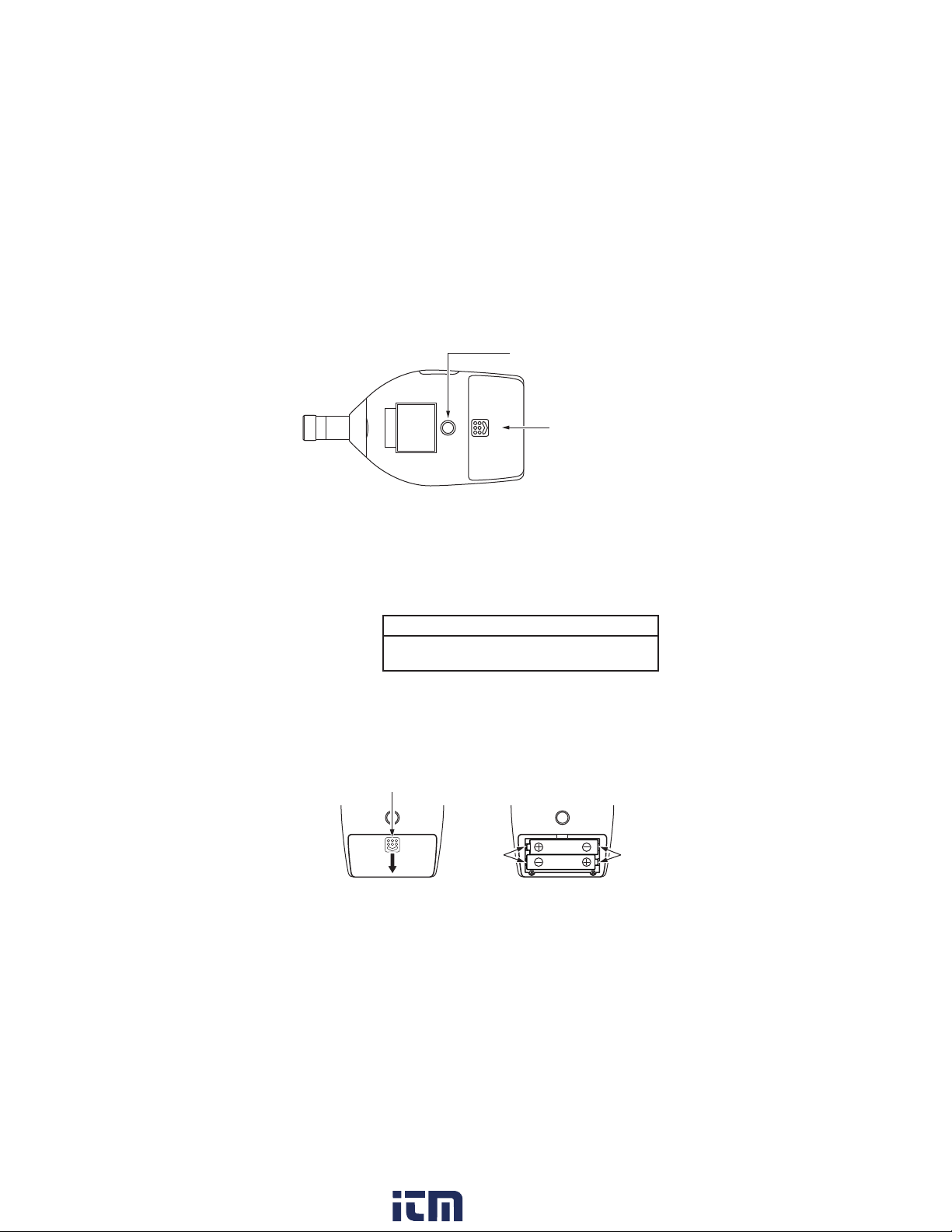
Controls and Functions........................................................................ 2
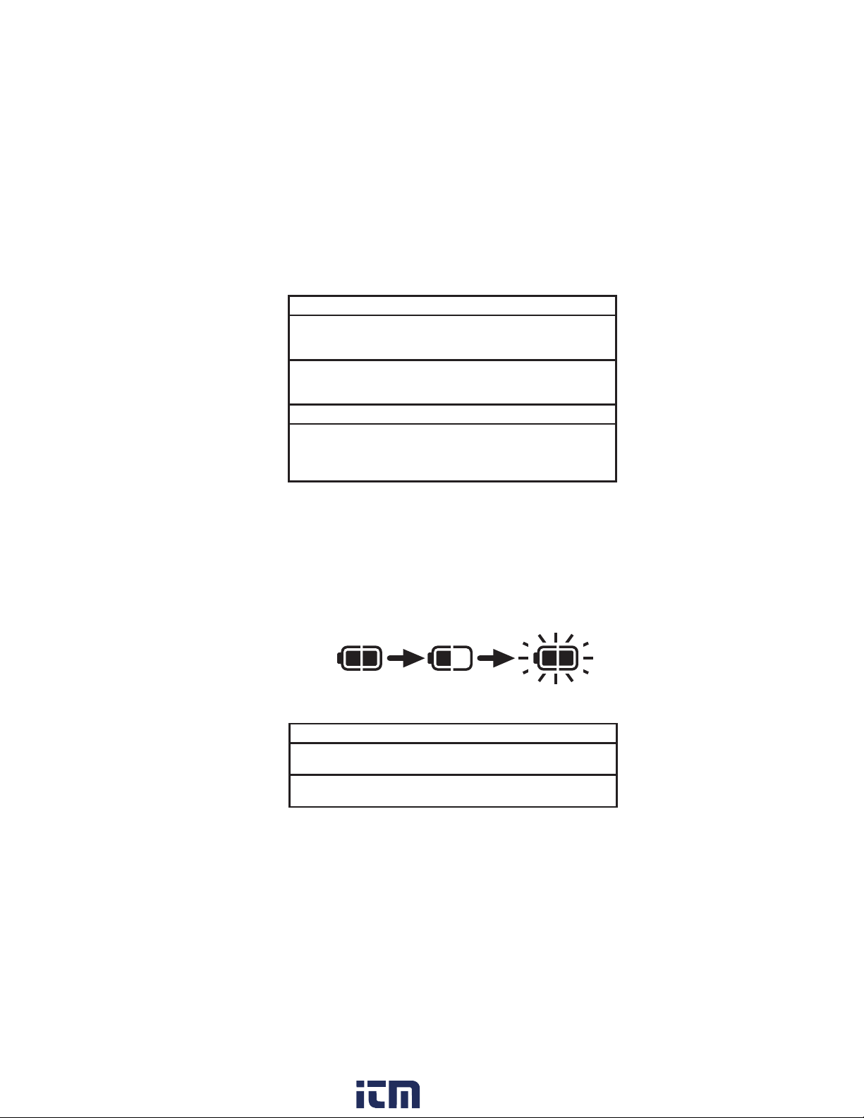
Batteries .............................................................................................. 4
Attachments ........................................................................................ 6
Windscreen .................................................................................... 6
Windscreen fall out prevention rubber........................................... 6
Silicon cover................................................................................... 7
Hand strap ...................................................................................... 8
Connecting external equipment ..................................................... 9
State transition diagram (functions and operation keys) ................... 10
Measurement screen and processing screen...................................... 12
Power on and off ............................................................................... 14
Measurement ..................................................................................... 14
Calibration......................................................................................... 15
Menu settings .................................................................................... 16
Sleep mode ........................................................................................ 18
Recalling stored data......................................................................... 19
Initializing......................................................................................... 20
Specications .................................................................................... 21
Description for IEC 61672-1.............................................................. 26
IEC61672-1 (JIS C 1509-1) Frequency Response ......................... 37
Reference incidence direction and reference point position......... 39
Frequency Response .................................................................... 39
Effect of Windscreen WS-14 ....................................................... 40
The greatest susceptibility conguration for radio frequency elds
. 42
Statement of conforming to the basic statement ......................... 43
Adjustment data for sound calibrator ........................................... 43
The lower and upper limits of the linear operating range ............ 43
Directional Characteristics .......................................................... 44
Random incidence response......................................................... 46
www. .com information@itm.com1.800.561.8187

iv
Precautions
•Operate the unit only as described in this manual.
•Do not touch any parts of the unit other than necessary for
operation.
•
Do not drop the unit. Protect it from shocks and vibration.
•The permissible environmental temperature range for operation
of the unit is -10 to +50°C. Relative humidity must be between
10% and 90%RH.
•Do not use or store the unit in locations which may be subject
to water, direct sunlight, high temperatures or humidity. Also
protect the unit from air with high salt or sulphur content, gases
or the inuence of chemicals.
•Do not forget to turn the unit off after use. Remove the batteries
if the unit is not to be used for some time.
•When disconnecting cables, always hold the plug and do not
pull the cable.
•To clean the unit, use only a dry cloth or a cloth lightly moistened
with water. Do not use chemical cleaning cloths, solvents or
alcohol-based cleaners to prevent the possibility of deformation
and discoloring.
•Do not insert any objects such as pins, metal scraps, conducting
plastic etc. into any opening on the unit.
•Do not disassemble the unit or attempt internal alterations.
•In case of malfunction, do not attempt any repairs. Note the
condition of the unit clearly and contact the supplier.
•When disposing of the unit or the batteries, follow national and
local regulations regarding waste disposal.
www. .com information@itm.com1.800.561.8187

1
Outline
This unit is a sound level meter that complies with the Japan
measurement law, JIS, and IEC. The microphone is a 1/2-inch
electret condenser (UC-52). It has a wide 107-dB linearity range,
measuring sound levels between 30 and 137 dB, with no need
to select the range. The unit has an LCD panel, operation keys,
an AC monitor output connector and a DC out connector. It is
able to measure the following items.
• Soundlevel Lp
• Equivalentcontinuoussoundlevel Leq
• Maximumsoundlevel Lmax
• Soundexposurelevel LE
• Cweightedpeaksoundlevel LCpeak
It is powered by two size AAA(IEC R03, LR03) batteries. The
main unit and preamplier are a single unit so it is not possible
to extend the microphone.
This unit has the following two level ranges.
Wide range: This measures the range between 30 and 137 dB
and allows simultaneous measurement of Lp, Leq,
Lmax, and LE.
Peak range: Along with the processing results for wide range,
this range also measures LCpeak, but the lower limit
for measurement becomes 65 dB.
Resume function
This function maintains the settings that have been congured
before power-off.
The following items are maintained:
• Measurementtime
• Timeweightingcharacteristics
• Levelrange
• Addressindication
The following items have predened settings upon startup.
• Frequencyweightingcharacteristic A
• Displayprocessingvaluetype Lp
www. .com information@itm.com1.800.561.8187

2
Controls and Functions
Front Panel
Microphone/preamplier
Microphone and preamplier are integrated in a single enclosure.
An extension cable cannot be used.
START/STOP key
Press to start or stop processing. Also used to change setting
values in the calibration screen, menu screen, and recall screen.
MODE key
Changes the processing result display in the measurement screen
and processing screen. Also used to change setting values in the
calibration screen, menu screen, and recall screen.
A/C/CAL key
This key selects the frequency weighting characteristics, calibra-
tion screen and recall screen. Pressing and holding this key in
the measurement screen changes it to the menu screen.
POWER key
Turns the unit on and off.
FT3432 SOUND LEVEL METER
START/STOP MODE A/C/CAL
POWER
MENU
START/STOP key
MODE key
A/C/CAL key
POWER key
Microphone
Preamplier
www. .com information@itm.com1.800.561.8187

3
Side View
External connector
This connector is composed of a DC out connector and an AC
monitor output connector. (The connector can only be used for
one purpose at a time.)
DC out connector
A DC signal corresponding to the sound level can be output from
here. The signal after frequency weighting, time weighting, and
logarithmic compression is output here (constant output when a
DC output cable is connected). Connect the unit with the optional
DC output cable to external equipment.
AC monitor output connector
An AC signal weighted with frequency weighting characteristic Z
is output here (constant output when an AC monitor output cable
is connected).
Connect the unit with the optional
AC monitor
output cable to external equipment.
When 110 dB is displayed, output is 1 Vrms
+600 mVrms
- 400 mVrms
(The upper limit of the output voltage is 1.8
Vrms
)
Strap mount
Attach the hand strap here (see page 8). Pass your wrist
through this strap when holding the unit for measuring.
DC out connector
AC monitor output connector
Strap mount
External connector
www. .com information@itm.com1.800.561.8187

4
Tripod mounting thread
Mount the unit on a camera tripod with this thread.
Battery compartment
Insert two size AAA (IEC R03, LR03) batteries here.
Batteries
Inserting the Batteries
Important
Make sure the unit is turn off before inserting
the batteries.
1.
Remove the battery compartment cover on the rear of the unit.
2. Insert two size AAA (IEC R03, LR03) batteries into the
battery compartment. Insert correctly as indicated in the
compartment.
3. Replace the battery compartment cover.
Rear View
Tripod mounting thread
Battery compartment
Battery
contact
Battery
contact
Press and pull in the arrow direction
Insert two size AAA
(IEC R03, LR03) batteries
Remove the battery
compartment cover
www. .com information@itm.com1.800.561.8187

5
Important
Take care not to reverse the (+) and (-) polarity when inserting
the batteries. If batteries are inserted with wrong polarity, the
unit willnot operate.
Always use two identical batteries, and replace batteries only
as a set. Mixing battery types or old and new batteries can
lead to damage.
Remove the batteries from the unit when it is not used.
Do not subject the battery spring contacts to excessive stress.
Doing so may weaken the elasticity of the battery spring
contacts, resulting in electrical contact failure between the
contacts and the batteries.
Battery life (at 23°C, using wide range)
Manganese batteries: approx. 3 hours
Alkaline batteries: approx. 9 hours
Battery life will be reduced by 20% when a DC output cable is
connected.
Battery indication
Indicates battery charge. When the indicator starts to ash, cor-
rect measurement is no longer possible. Replace the batteries
with fresh ones.
Full charge Indicator flashing
(replace the batteries)
Important
If the indicator starts flashing during processing, processing
will end at that point.
You cannot start processing with the START/STOP key when
the battery indication is ashing.
www. .com information@itm.com1.800.561.8187

6
Attachments
Windscreen
We recommend attaching the windscreen to reduce wind noise.
Windscreen fall out prevention rubber (hereafter called
“fall out prevention rubber”)
Prevents the windscreen from dropping off the microphone.
This is attached to the unit at the time of shipment.
Important
The windscreen can easily drop off the unit,
so we recommend attaching the fall out pre-
vention rubber.
Be sure to follow the instructions in the fol-
lowing diagram when attaching or detaching
the fall out prevention rubber. Turning it in the
opposite direction may loosen the microphone
and cause it to fall off.
FT3432 SOUND LEVEL METER
Turn the fall out
prevention rubber
only in this
direction.
SOUND LEVEL METER NL-27
START/STOP MODE A/C/CAL
POWER
MENU
Windscreen
Fall out prevention
rubber
www. .com information@itm.com1.800.561.8187

7
Silicon cover
The silicon cover protects the unit from shocks and also makes
it easier to grip when held.
Fit it to the unit with the windscreen removed, as shown in the
following diagram.
Note
You cannot use external connector when the silicon
cover is tted.
You can attach the hand strap to the silicon cover
strap mount.
FT3432 SOUND LEVEL METER
START/STOP MODE A/C/CAL
POWER
MENU
SOUND LEVEL METER
NL-27
START/STOP MODE A/C/CAL
POWER
MENU
FT3432 SOUND LEVEL METER
START/STOP MODE A/C/CAL
POWER
MENU
Silicon cover
strap mount
www. .com information@itm.com1.800.561.8187

8
Hand strap
To help prevent dropping of the unit, pass your wrist through
this strap when holding the unit for measuring.
Attach the hand strap as shown below.
Note
Attach the hand strap to the silicon cover if you
have tted the unit with the silicon cover.
Strap mount Hand strap
When you have not fitted the silicon cover
POWER
When you have fitted the silicon cover
Silicon cover strap mount
www. .com information@itm.com1.800.561.8187

9
Connecting external equipment
You can connect external equipment, such as a HIOKI Memory
HiCorder to the external connector.
Connect as shown in the following diagram.
Note
The connector has the ability to act as a DC out
connector and an AC monitor output connector, but
it can perform only one of these functions at a time.
FT3432 SOUND LEVEL METER
START/STOP MODE A/C/CAL
POWER
MENU
External connector
DC output
cable
CC-98D
Memory HiCorder, DMM etc.
Memory HiCorder etc.
AC monitor
output cable
CC-98A
FT3432
www. .com information@itm.com1.800.561.8187

10
START/STOP key
START/STOP key, or
after the measurement
time has elapsed
Processing
screen
Measurement
screen
Calibration
screen
Reduce volume with
the START/STOP key
Move the address
down with the
START/STOP key
Move the address up
with the MODE key
Raise volume with
the MODE key
A/C/CAL key
A/C/CAL key
A/C/CAL key
A/C/CAL key
Frequency
weighting
characteristic A
Frequency
weighting
characteristic C
External calibration
Internal calibration
Recall screen
Startup Power on
A/C/CAL key
Pressing the MODE key in the measurement screen or processing
screen changes the display in the following order.
LpLeq Lmax LE( LCpeak) Lp
LCpeak only appears when peak range is selected.
Press and
hold the
A/C/CAL
key
Press and
hold the
A/C/CAL
key
Menu screen
Range setting
A/C/CAL key
A/C/CAL key
A/C/CAL key
Setting time
weighting
characteristics
Setting
measurement
time
Change the setting with the
START/STOP key or MODE key
Wide Peak
Change the setting with the
START/STOP key or MODE key
F S
Change the setting with the
START/STOP key or MODE key
1 m 5 m 10 m 1 h 1 m
State transition diagram (functions and operation
keys)
www. .com information@itm.com1.800.561.8187

11
START/STOP key
START/STOP key, or
after the measurement
time has elapsed
Processing
screen
Measurement
screen
Calibration
screen
Reduce volume with
the START/STOP key
Move the address
down with the
START/STOP key
Move the address up
with the MODE key
Raise volume with
the MODE key
A/C/CAL key
A/C/CAL key
A/C/CAL key
A/C/CAL key
Frequency
weighting
characteristic A
Frequency
weighting
characteristic C
External calibration
Internal calibration
Recall screen
Startup Power on
A/C/CAL key
Pressing the MODE key in the measurement screen or processing
screen changes the display in the following order.
LpLeq Lmax LE( LCpeak) Lp
LCpeak only appears when peak range is selected.
Press and
hold the
A/C/CAL
key
Press and
hold the
A/C/CAL
key
Menu screen
Range setting
A/C/CAL key
A/C/CAL key
A/C/CAL key
Setting time
weighting
characteristics
Setting
measurement
time
Change the setting with the
START/STOP key or MODE key
Wide Peak
Change the setting with the
START/STOP key or MODE key
F S
Change the setting with the
START/STOP key or MODE key
1 m 5 m 10 m 1 h 1 m
www. .com information@itm.com1.800.561.8187

12
Measurement screen and processing screen
Processing
mark
Processing re-
sult under range
indication
Sound level
under range
indication
Frequency weighting
characteristics
Processing re-
sult symbol
Time weighting
characteristics
Level indication
Bar graph, lev-
el range scale
Processing re-
sult overload
indication
Sound level
overload indi-
cation
Battery indica-
tion
Address number
Elapsed time
Measurement time
Measurement time
The measurement time set in the menu screen (see state transi-
tion diagram, page 11).
Elapsed time
The amount of time elapsed since processing started.
Address number
The address where the processing result (the next process result
in the measurement screen) is stored.
Battery indication
Indicates battery charge. (see page 5)
Bar graph, level range scale
Shows the sound level in a bar graph.
Sound level overload indication
Shows that the sound level has exceeded the measurement range.
www. .com information@itm.com1.800.561.8187

13
Processing result overload indication
Appears during processing when the sound level exceeds the
measurement range, and remains until the next process starts
(when a processing result is shown).
Level indication
Shows the sound level (Lp) and each processing result (Leq, Lmax,
LE, and LCpeak) as digits. Switch the display with the MODE key.
LCpeak is processed and shown only when peak range (see page
16) is selected.
Time weighting characteristics
Shows the time weighting characteristics selected in the menu
screen.
Processing result symbol
Shows the relevant symbol for the displayed processing result
(Leq, Lmax, LE, or LCpeak).
Frequency weighting characteristics
Change with the A/C/CAL key. See the state transition diagram
(page 10).
Processing result under range indication
If the sound level falls below the measurable limit (-0.6 dB) dur-
ing processing, this appears until the next process starts (when
a processing result is shown).
Sound level under range indication
Appears when the sound level falls below the measurable limit
(-0.6 dB).
Processing mark
Flashes during processing.
www. .com information@itm.com1.800.561.8187

14
Power on and off
Press the POWER key for 0.5 seconds or more to turn the power
on or off.
Measurement
Selecting frequency weighting characteristics
In the measurement screen, press the A/C/CAL key to select
either frequency weighting characteristic A or C. (See the state
transition diagram on page 10)
Processing (measurement)
Press the START/STOP key to start the processing.
The processing mark ashes during processing. Additionally,
pressing the MODE key switches the display to show processing
results (Lp, Leq, Lmax, LE, or LCpeak) made up to that point.
Processing stops when the measurement time elapses or you
press the START/STOP key.
Storing processing data
When processing stops, the Leq, Lmax, LE, or LCpeak process-
ing results are automatically stored, and the address number
increases by one.
www. .com information@itm.com1.800.561.8187

15
Calibration
Internal calibration (calibration with an electronic signal)
Calibration with the built-in oscillator (1 kHz, sinusoidal wave).
In the measurement screen, press the A/C/CAL key to switch
to the internal calibration screen.
(See the state transition diagram on page 10)
Press the START/STOP key (Down) or MODE key (Up) to adjust
the volume to 94.0 dB.
Sound calibration (calibration with a sound
calibrator)
Use optional sound calibrator NC-74 or NC-72A.
In the internal calibration screen, press the A/C/CAL key to
switch to the sound calibration screen.
Attach the microphone to NC-74 or NC-72A and turn NC-74 or
NC-72A on. Wait at least 30 seconds, then press the START/
STOP key (Down) or MODE key (Up) to adjust the volume to
the following values.
NC-74 : 93.9 dB, NC-72A :114.0 dB.
Internal calibration screen
“Int”, “Cal”, and “94.0dB”
appear on the display.
The frequency weighting
characteristic is fixed to
C and the time weighting
characteristic is xed to F.
Sound calibration screen
“Aco” and “Cal” appear
on the display.
The frequency weighting
characteristic is fixed to
C and the time weighting
characteristic is xed to F.
www. .com information@itm.com1.800.561.8187
Other manuals for FT3432
1
Table of contents
Other Hioki Measuring Instrument manuals

Hioki
Hioki MR8880-20 User manual

Hioki
Hioki 3196 User manual

Hioki
Hioki RM2610 User manual

Hioki
Hioki IM3523A User guide

Hioki
Hioki IM7580 User manual

Hioki
Hioki Super megohm SM7110 User manual

Hioki
Hioki PW3390 Use and care manual

Hioki
Hioki PR8111 User manual

Hioki
Hioki BT3562-01 User manual

Hioki
Hioki 9695-02 User manual
Popular Measuring Instrument manuals by other brands

Badger Meter
Badger Meter ILR710 Installation and operation

PCE Instruments
PCE Instruments PCE-CP Series user manual

KERN Optics
KERN Optics ORA 90 BE operating manual

Delmhorst
Delmhorst BDX-20 quick start guide

AXIOMATIC TECHNOLOGY
AXIOMATIC TECHNOLOGY micro People Counter user guide

Growatt
Growatt Shine3G Quick Installation Guideline