Michelin Wheely-Safe Manual
C
M
Y
CM
MY
CY
CMY
K
MICHELIN LOGO LSCAPE WHITE.pdf 1 18/06/2018 11:36
HEAVY fleet
FITMENT PROCEDURE
v2-feb2019

important information
fitment information
Please note it is imperative that all staff/personnel are aware that, although the MICHELIN Wheel
Security System is an in-motion wheel loss and hub/brake temperature detection system, your
normal tyre and wheel removal, maintenance & walk round procedures/policies must still be
adhered to. You cannot rely on this system as a means of omitting any undertaking of these
activities or responsibilities. It is also the case for the tyre pressure monitoring system that all
normal inspection & maintenance procedures are adhered to.
No Liability can be offered by Wheely Safe Ltd for any loss or damages incurred as a result of the
devices being fitted.
WORKING TEMPERATURES OF THE SYSTEM
Solar receiver -20ºC upto 65ºC
Solar booster -20ºC upto 80ºC
TPMS sensor - 40ºC upto 120ºC
Wheel loss sensor - 40ºC upto 120ºC
NOTE:
It is important that these devices are fitted in the correct locations (as per the enclosed pictures)
for ease of identifying.
All sensors are colour coded as per vehicle positions to ease early identification in an alert
situation, being Black sensors (front) of vehicle, e.g. in a 2x axle bus, black sensors on the front
axle and for a tractor/trailer, the black sensors will be on the tractor unit. The rear sensors will be
Blue in colour.
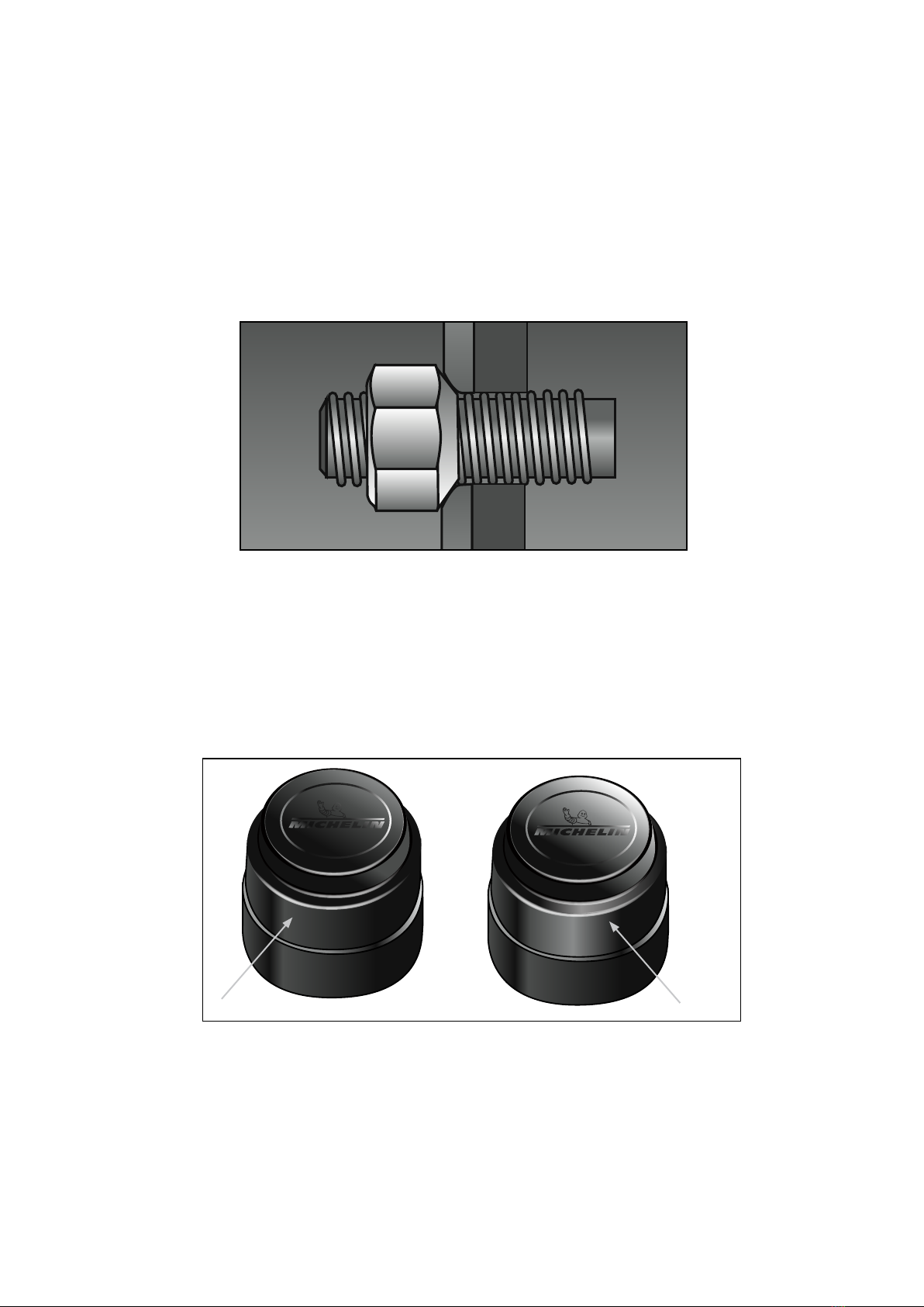
If you are fitting the Tyre Pressure sensors to inner wheels, make sure you have Brass extensions
fitted (NOT PLASTIC- AS THESE DO NOT EMIT AIR FOR THE SENSOR TO MONITOR THE TYRE)
2

fitment of the wired receiver.....................................4
fitment of the solar receiver.....................................5
fitment of wheel loss sensor and bracket..............6 - 13
fitment of tyre pressure monitoring
sensors (TPMS)................................................................14 - 17
fitment of fused signal booster (wired)..................18 - 19
fitment ofsignal booster (solar).............................20 - 21
fitment of telematics receiver (wired).....................22
fitment of telematics receiver (solar).....................23
Pressure checker..........................................................24 - 25
Care and maintenance..................................................26
Product Disclaimer and Warranty.............................27
warnings alarms...........................................................28
contents:
3

fitment of the wired receiver
Please connect the RED Wire directly to a vehicle 12V/24VIgnition fed power supply (Positive).
The Black Wire is connected to a Ground wire (Negative).
Consult manufacturers wiring guidelines where applicable to avoid any warranty issues.
Remove the backing from the adhesive pad at the rear of the receiver taking care not to touch the adhesive
surface.
Normal Operation Mode
The “Michelin” Logo will be permanently lit WHITE.
Stationary Sleep Mode
When the vehicle is stationary for more than 15 minutes and with the ignition on the receiver will go into
Stationary Sleep Mode. No Lights will be on at all in this mode.
No Power
If the receiver has no power during a journey then the “Michelin” Logo will not be lit. This situation must
be remedied by reconnecting to the power source.
4
The receiver should be mounted on a clean even flat surface so that it does not obscure the view of the
road or any instrumentation but is clearly visible to the driver from a normal driving position.
ENSURE THAT THERE ARE NO TRAILING WIRES AFTER INSTALLATION.
5
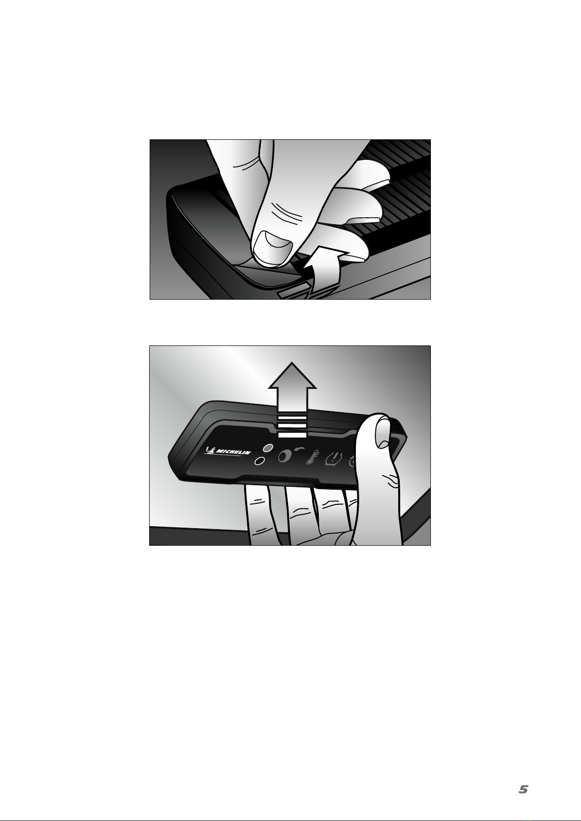
fitment of the SOLAR receiver
Remove the backing from the adhesive pad at the rear of the receiver taking care not to touch the adhesive
surface.
Normal Operation Mode
The power icon will flash once every 30 seconds when in journey mode.
Low power
When the solar receiver has less than 15% power the power icon will flash red every 10 seconds.
To charge the solar receiver plug the charger into the side of the receiver and connect to a power source.
The power icon will stay permanently white when fully charged.
Stationary Sleep Mode
When the vehicle is stationary for more than 15 minutes the receiver will go into Stationary Sleep Mode.
No Lights will be on at all in this mode.
Find the ideal position for the receiver on the windscreen (ideally towards the top of the windscreen)
ensuring that it is outside the wiper sweep. Ensure the solar panel is not blocked by the black border that
exists around many windscreens.
The area of the windscreen where the receiver is to be fitted should be clean and free from dust or grease.
Place the receiver in the correct position and push firmly against the widscreen, holding and pushing for up
to 10 seconds.
6
fitment of wheel loss sensor and bracket
PREPARING & PLANNING TO FIT THE WHEEL LOSS SENSORS & BRACKETS Get 2 sensors and brackets for
each outer wheel ready to fit
sensors : Black for front-blue for rear
Note:
If the wheel fixing has a conical or spherical stud fixing, please
contact Wheely-Safe prior to installing the system, for guidance.
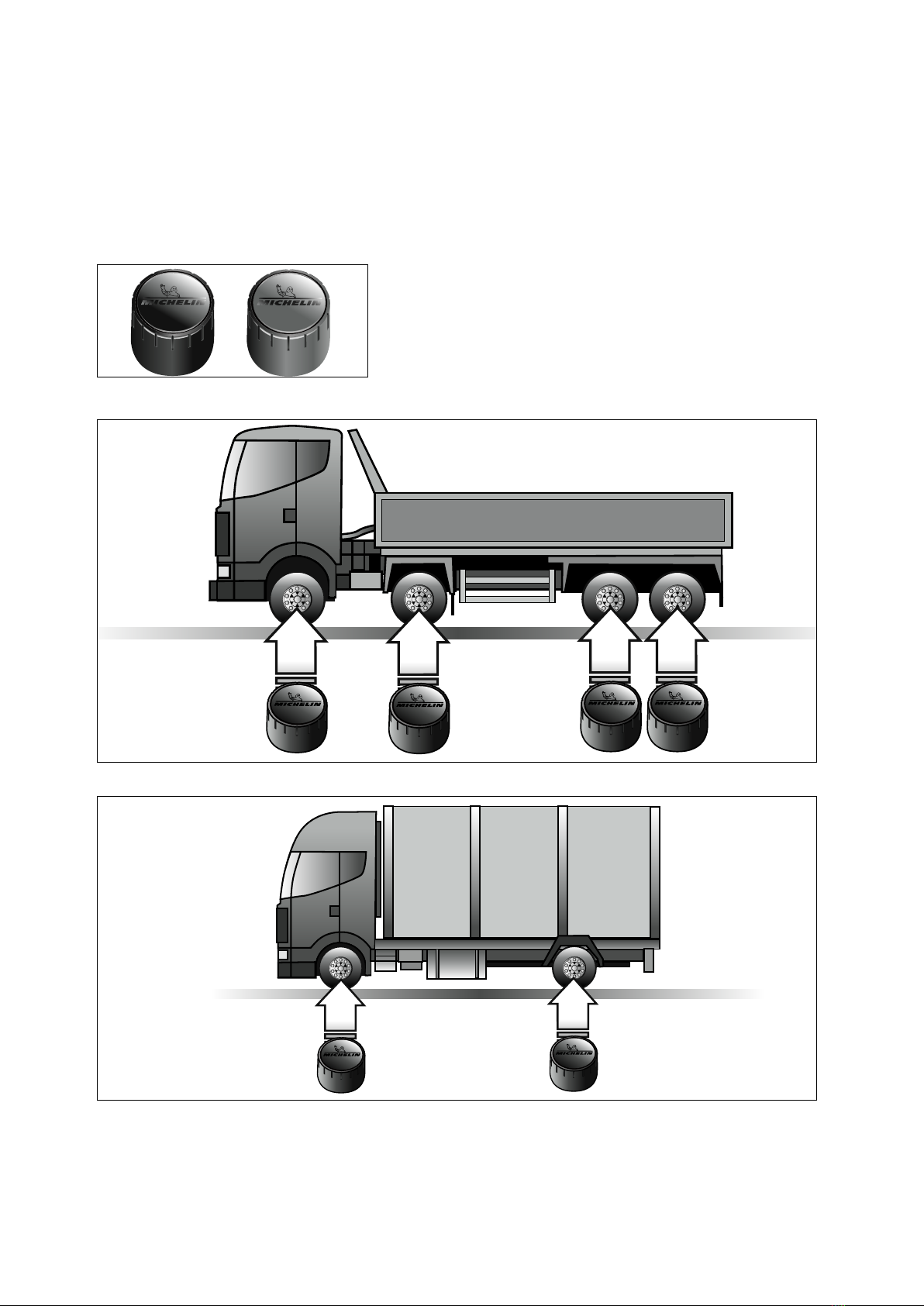
The top of the sensor is identified by a Michelin logo.
blue for rear
black for FRONT

7
The black sensors are fitted on the front (tractor) wheels and blue sensors fitted to rear (trailer) wheels.
For rigid vehicles, coaches & buses: Black at front, Blue at rear
Different coloured sensors make it easer to identify the fault when an alert occurs on the receiver and to assist
the driver/engineer in locating where the fault may lie on the vehicle. This is in addition to the sensor also
flashing for 3 minutes.

8
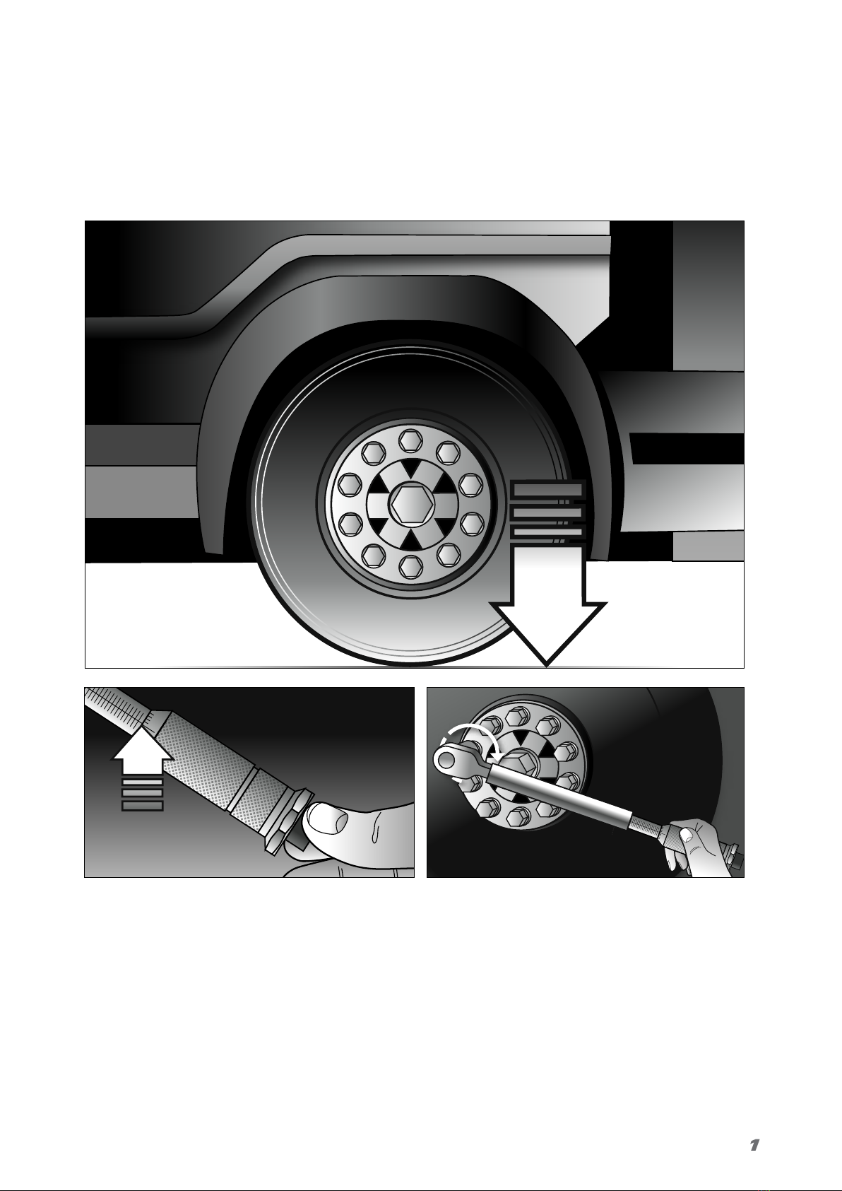
The wheel that requires the wheel loss system to be fitted must be jacked up so that the tyre is off
the ground.
Remove all nuts and the wheel.
illus
jacking wheel up
fitment of wheel loss sensor and bracket
continued

9
Both the mating face of the wheel rim and bracket should be clean and free from dirt, paint, rust
and grease.
Put the wheel back on to the hub.

10
fitment of wheel loss sensor
and bracket - continued
WHEN FITTED CORRECTLY THE TOP OF THE SENSOR WILL PROTRUDE SLIGHTLY ABOVE THE BRACKET.
11
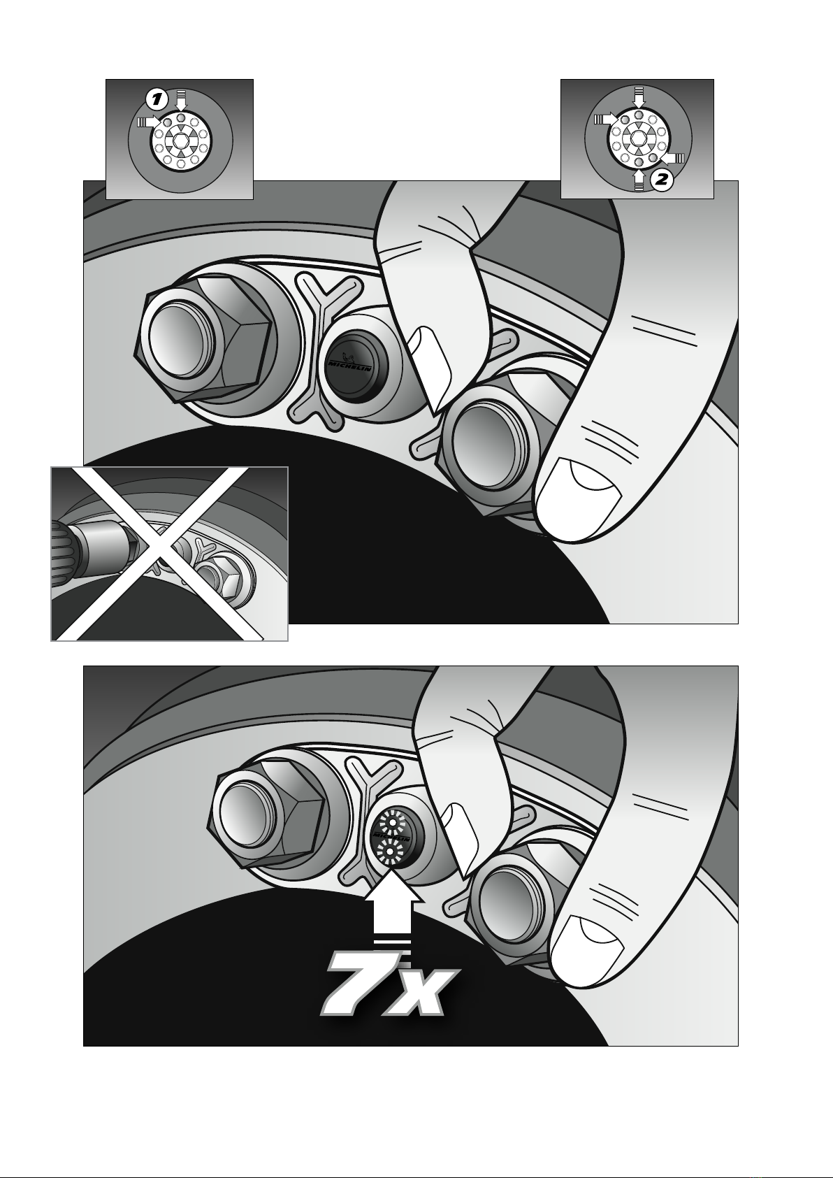
Position the sensor and brackets diagonally
opposite each other.
When fitting and tightening the wheel nuts, and in its clamped position, the sensor LED will flash
7 times for 18 seconds This is the indication that the sensor is activated and the user can have the
confidence that the Michelin Wheel Security System is working.

12
REFER TO A RECOGNISED INDUSTRY STANDARD WHEEL SECURITY BEST PRACTICE GUIDELINE
FOR NUT TIGHTENING SEQUENCE.
fitment of wheel loss sensor
and bracket - continued
13
IMPORTANT Failure to release the clamping force of ALL the wheel nuts and only releasing the clamping
force of the nuts required to fit the brackets could result in a torque imbalance. Any torque imbalance
then has the potential to result in nuts coming loose in a very short journey time.
Note: **On Completion of fitting the Bracket & Sensor**
All wheels changed/disturbed must be rechecked for tightness before entering service and a torque
wrench must be used for checking wheel nut tightness to manufacturer’s guidelines. Then your own
company Wheel removal Maintenance & Walk round procedures/policies must be adopted for ongoing
checks thereafter.
Then follow your own proven wheel security procedure
14
fitment of tyre pressure monitoring sensors (TPMS)
PLEASE ENSURE THAT ONLY BRASS EXTENSIONS ARE USED FOR INNER WHEELS WHEN
FITTING SENSORS (NOT PLASTIC- AS THESE DO NOT EMIT AIR FOR THE SENSOR TO
MONITOR)
Fitment information – When fitting the TPMS sensor you should ensure
that IT is not touching the wheel rim.
The black sensors are fitted on the front (tractor)
wheels and blue sensors fitted to rear (trailer) wheels.
For rigid vehicles, coaches & buses: Black at front, Blue at rear
Different coloured sensors make it easer to identify the fault when an alert occurs on the receiver and to
assist the driver/engineer in locating where the fault may lie on the vehicle. This is in addition to the
sensor also flashing for 3 minutes.
15
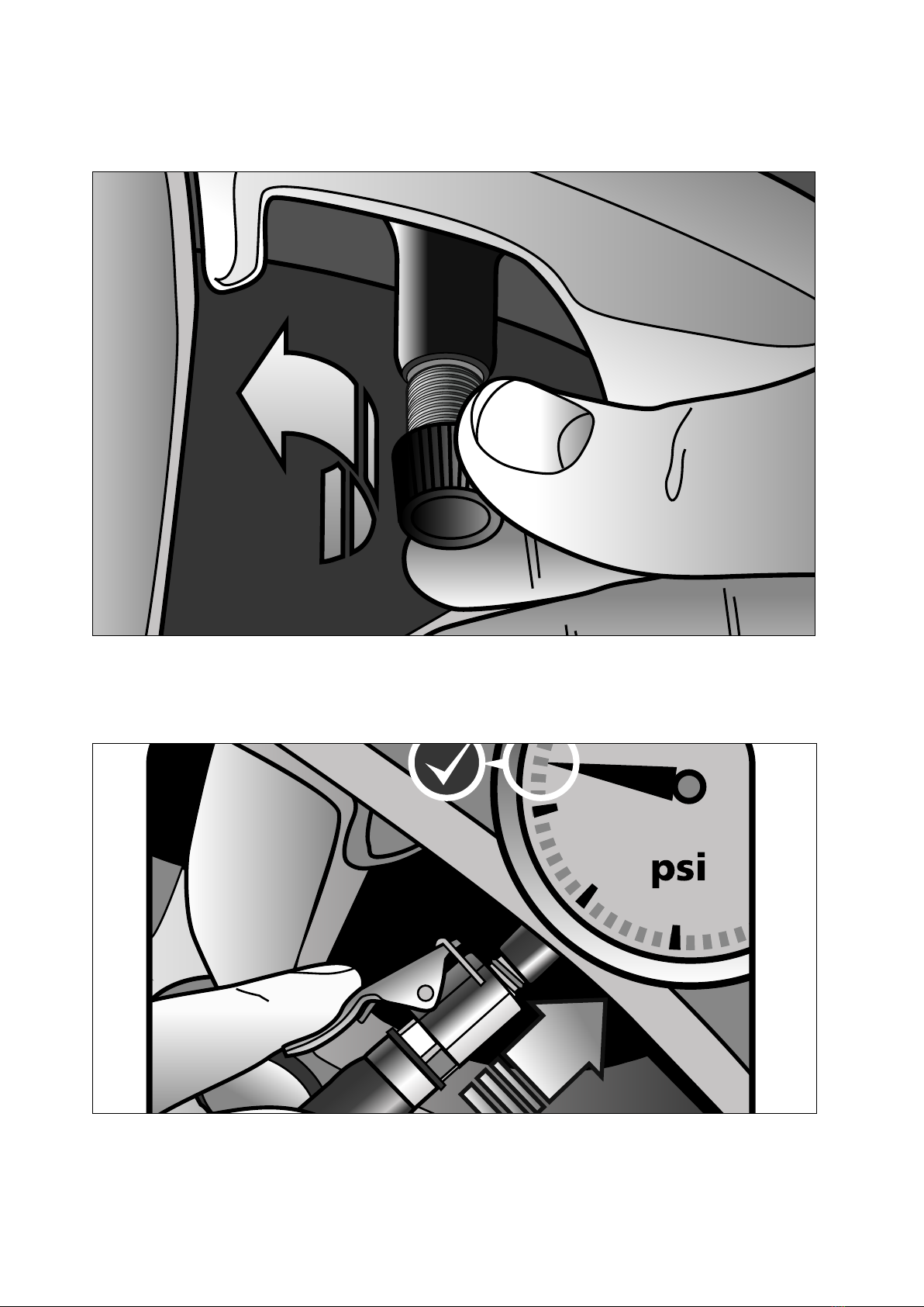
Remove the dust cap
Check the tyre pressure is correct before fitting the TPMS sensor. The target pressure is for the
normal COLD operating temperature recommended by the vehicle manufacturer.
C
M
Y
CM
MY
CY
CMY
K
MICHELIN TYRE INFLATEv3.pdf 1 15/05/2017 12:51
16
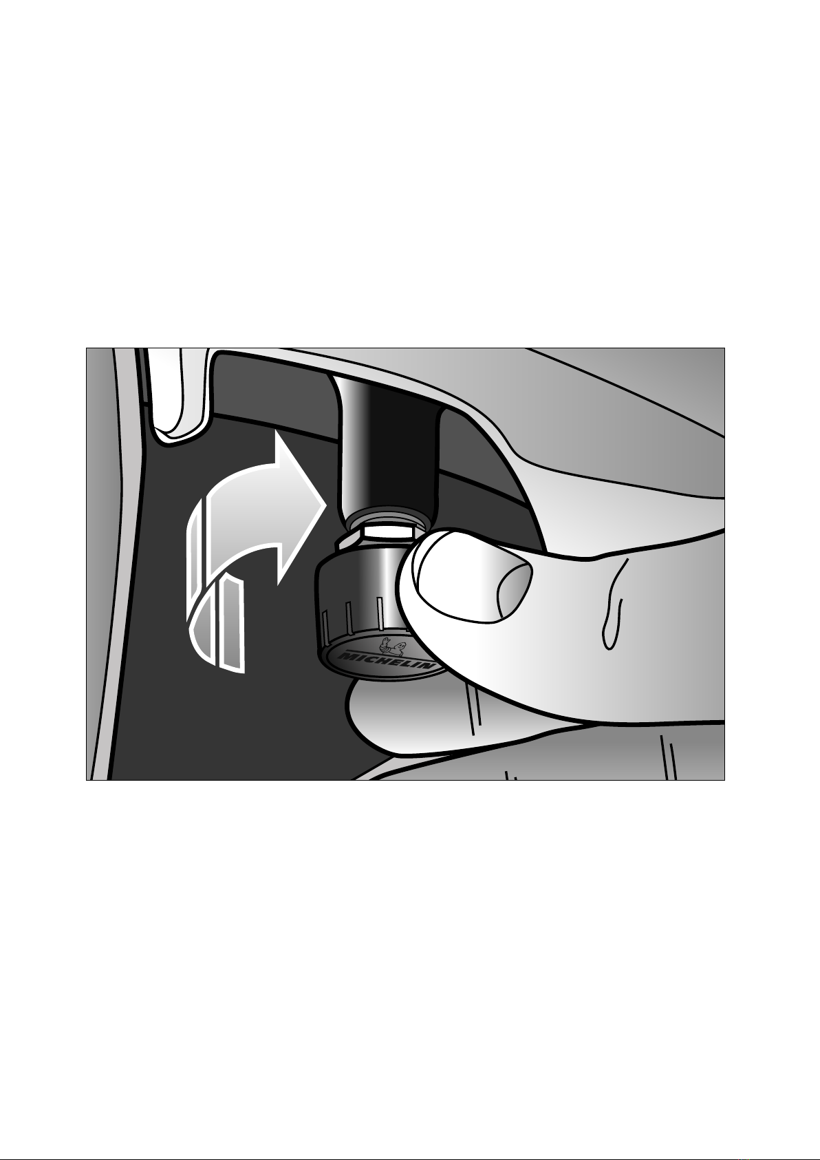
Twist on the sensor ( finger tight)
Check for the red LED flashing while the clever sensor self-calibrates to the current tyre pressure.
fitment of tyre pressure monitoring sensors (TPMS)
continued
17
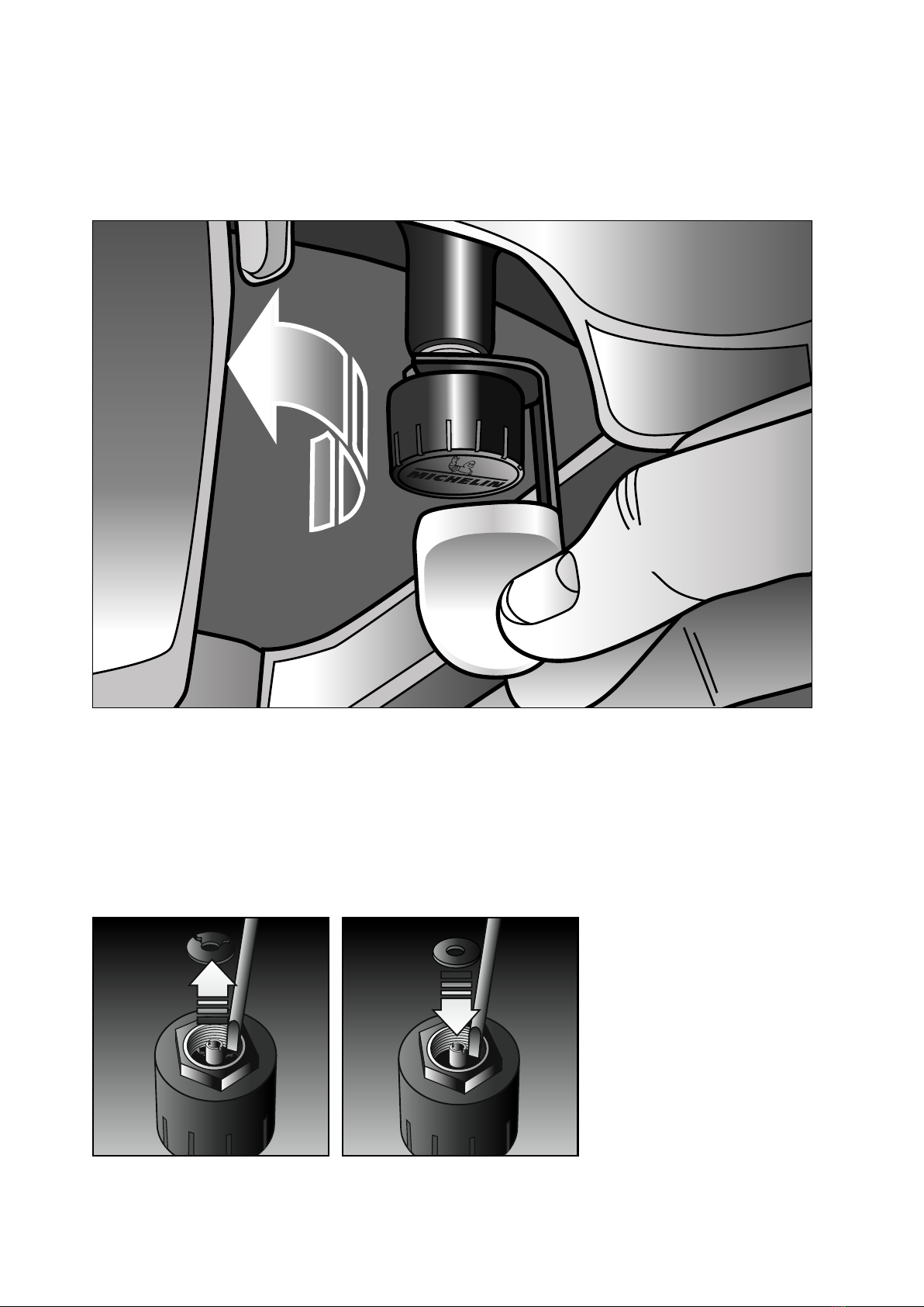
sensor gasket replacement
OPTIONAL:
If using anti-theft nuts attach these to the tyre valve by screwing the nut onto the valve ensuring you leave
enough thread so that the TPMS sensor can be fully screwed onto the tyre valve. Screw the TPMS sensor onto
the valve and then using the lock nut tool tighten the nut back towards the TPMS sensor until tight. During the
tightening process it is imperative that you hold the TPMS sensor in place to stop it
For your information, If the gasket is damaged or perished during the 12-month warranty period the customer
needs to replace it with the spare one that will be provided when they first purchase the product.
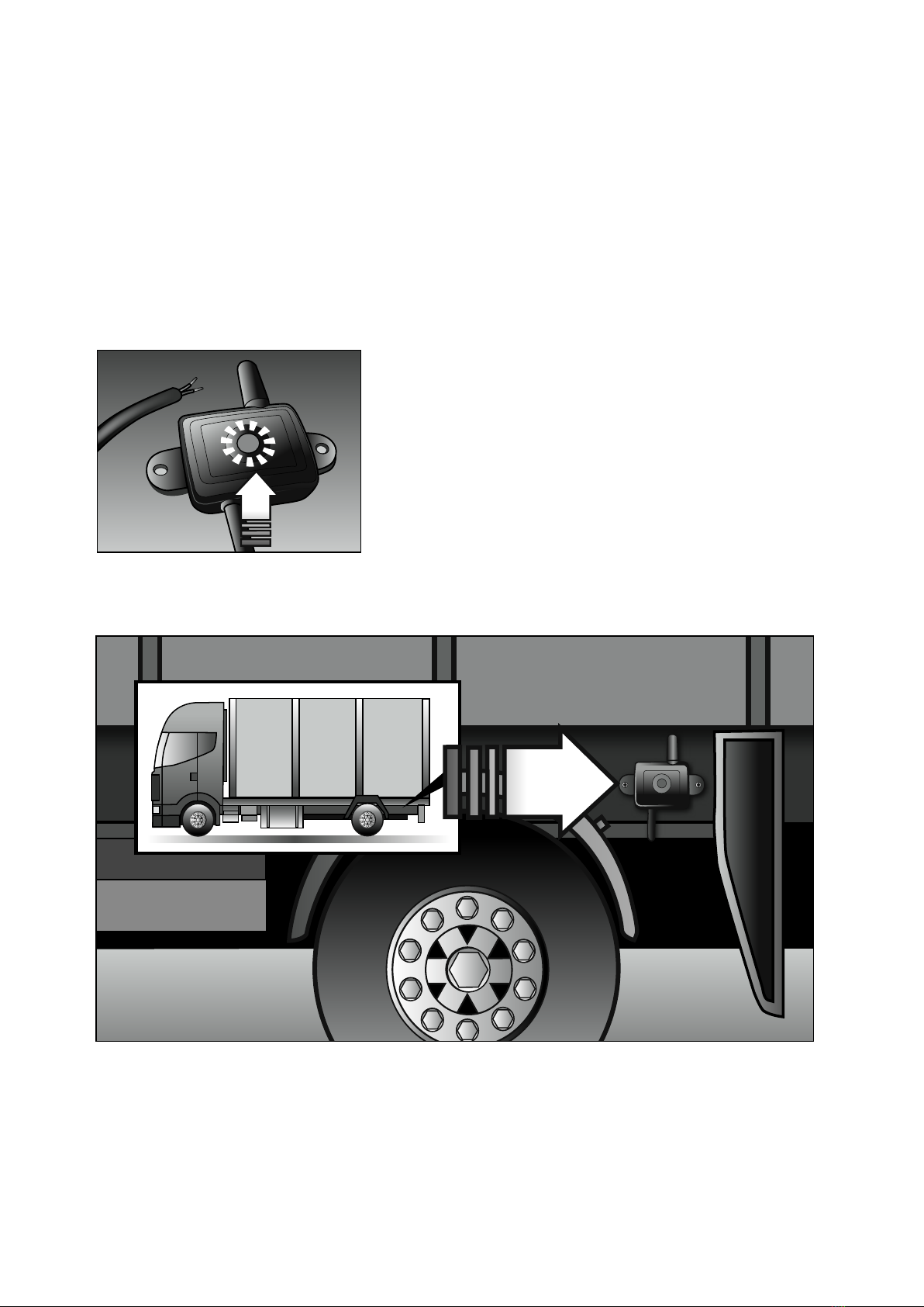
18
fitment of fused signal booster (wired)
Function:
To boost the signal from the rear wheel sensors to receiver.
note: fit one booster to either side of the vehicle. 2 x boosters for
trailers and rigid chassis. None required for tractor units.
Fitting position - Rigid
The signal booster is fitted as close to the rear most sensor (wheel loss or TPMS) as possible. This area will
normally be the rear most axle. You are not required to fit a booster on the tractor unit.
RED Wire: connect to vehicle 12V/24V power supply directly(12~24V)
Black Wire: connect to Ground wire.
On rigid vehicles , where possible, connect to a permanent power
source so that the booster is powered when the ignition is off.
For trailer fitment please wire into a positive feed and test by
connecting to a suitable tractor unit.
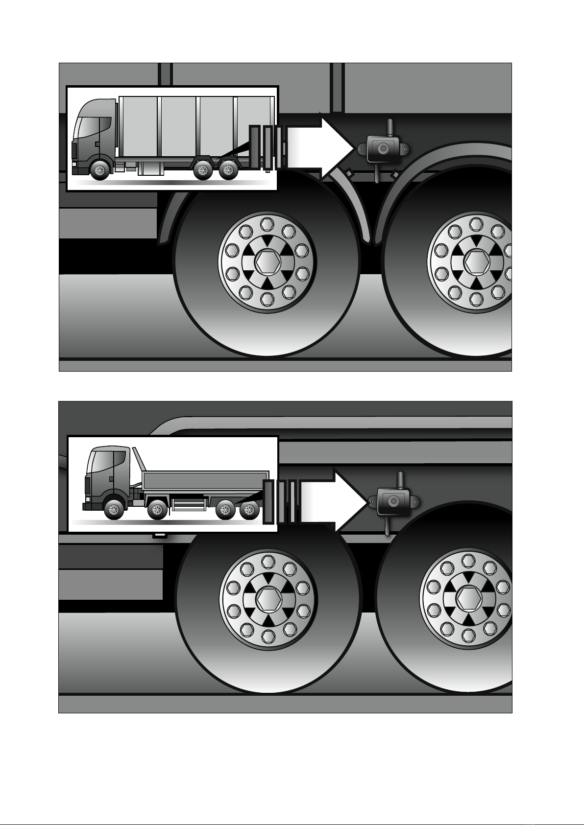
19
Fitting position - Rigid twin axle
Fitting position - Trailer

20
fitment of signal booster (solar)
POSITION
OPTION 1
POSITION
OPTION 2
The solar booster should be fitted externally in an area that is close to the rear most sensors and is visible to
daylight. Because of the vast variance in trailers and rigid vehicles a degree of common sense needs to be
applied. Fit 2 x boosters, one each side of a rigid vehicle or trailer (note, boosters are not required for tractor
units) Fit in an area that is close to the rear most sensors which can be above them, in-front of or behind them.
The roof can be considered as an option. The rear of the vehicle should also be considered as an option if there
is no other obvious area available. Metallic or glass surfaces are acceptable as a fitting surface, with a none
metallic surface being preferred.
Note:
Fit one booster,
externally, to either side
OR TO THE REAR of the
vehicle.
The fitting area
should be cleaned and
free from rust/dirt/
grease.
The signal booster should be fitted as close to the rear TPMS/Wheel loss sensor as possible.
Table of contents
Other Michelin Automobile Accessories manuals


