Michelin M4 Series User manual

03/11/22
CAN
GPS
GSM/GPRS
Default
Init
M4xx Series
PRODUCT INSTALL GUIDE
V1.9.9
10001
Christian Ståhle
eLearning Team
-
MCF Internal
Reference No:
Version:
Date of Version:
Author:
Approved by:
Translated by:
Classication:

2
Product Install Guide – M4xx Series
03/11/22 | V1.9.9
1. table of contents
1. TABLE OF CONTENTS 2
2. IMPORTANT NOTES 4
3. REQUIRED TOOLS AND CONSUMABLES 5
4. M4XX VERSIONS 6
5. PARTS 7
6. WIRING DIAGRAM 8
M40X 8
M41X 9
VEHICLE SPECIFICS 10
7. POWER SUPPLY 10
+POWER 10
+IGNITION 10
GROUND 10
POWER I/O CONNECTOR 10
8. IGNITION 11
9. SOLDERING METHOD 12
10. CRIMPING TERMINAL METHOD 12
11. ANTENNAS 13
INTERNAL ANTENNAS (M41X) 13
GSM & GSM/LTE ANTENNA (M40X) 15
GPS ANTENNA (M40X) 15
GSM, GSM/LTE & GPS POSITIONS (M40X) 16
DUAL ANTENNA (GSM/GPS) (M400/3) 16
12. CAN (OPTIONAL) 17
13. HMI (OPTIONAL) 18
INSTALLATION 18
POSITION 18
FEATURES 18
14. CABLE ROUTING 19
LOOMING 19
ROUTING 19
15. UNIT MOUNTING 20
SECURING THE UNIT 20
ORIENTATION 20
POSITIONING 20
M41X 20

3
Product Install Guide – M4xx Series
03/11/22 | V1.9.9
1. table of contents
16. I/O PROTECTION AND WARRANTY/TAMPER SEALS 21
ATTACHING THE I/O PROTECTION 21
WARRANTY/TAMPER STICKERS 21
17. COMMISSIONING 22
MASTER MANAGER MOBILE 22
VEHICLE INFORMATION 22
CONFIGURATION 22
INSTALL INFORMATION 22
VALIDATION 22
SPECIALIST SOLUTIONS 22
18. INPUT/OUTPUT (OPTIONAL) 23
INPUT COMPATIBILITY 23
19. TACHOFRESH (OPTIONAL) 24
TACHOFRESH 24
COMPATIBILITY 24
WIRING 24
20. GRITTERS (OPTIONAL) 25
COMPATIBILITY 25
WIRING 25
21. TEMPERATURE (OPTIONAL) 26
COMPATIBILITY 26
WIRED PROBES WIRING 26
WIRED PROBES INSTALLATION 26
WIRELESS TEMPERATURE 26
22. DEVICE OVERVIEW 27
LED SEQUENCE TROUBLESHOOTING 27
UNIT ICONOGRAPHY 27
23. CERTIFICATION INFORMATION 28
USA FCC - M405 / M404 + HMI + SCN4 28
CANADA ISED - M405 / M404 + HMI + SCN4 28
SOUTH AFRICA ICASA - M405 / M404 + HMI + SCN4 28
AUSTRALIA AND NEW ZEALAND RCM - M405 + HMI + SCN4 28
24. CONTACTS 29
25. VERSION HISTORY 29
FROM V 1.9.9 ONWARDS 29

4
Product Install Guide – M4xx Series
03/11/22 | V1.9.9
NOTE! Read carefully this contains important information.
• Before you begin installing and commissioning this equipment please ensure that you have read
this manual thoroughly referring to any supplementary information provided for the OBU as
required.
• Failure to comply with the following Warnings, Approval and Safety information may invalidate the
warranty, certication or type approval of this product.
• In order to maximise any insurance discounts that may apply it is essential that all installation
and service work is carried out in regulations of the country. It is strongly recommended that the
OBU (On Board Unit) is installed and commissioned by suitably trained and qualied personnel,
accredited and registered by the Vehicle Systems Installation Board.
• Before working on any connectors or wires, turn the ignition OFF and wait 5 minutes, for sleep
mode to kick in.
• Never turn the ignition ON if a connector is disconnected.
• A battery conditioning test must be completed during the pre-installation vehicle checks. If the
battery is defective, or requires recharging you must inform the customer and record this in your
report before proceeding with the installation.
• Never operate the OBU without the correct antennas, or suitable articial loads, connected.
• To minimise interference 20 cm (7.87 inch) must be maintained between the GSM antenna and the
GPS antenna, all persons, and electronic components.
• The user of all or part of the equipment is warned that any changes or modications not expressly
approved by Masternaut may prohibit its use.
• With the exception of specic installations with properly rated parts, this equipment should not be
operated in hazardous environments e.g; areas with ammable vapours or explosive materials.
• This equipment should not be operated within aircrafts or in close proximity to medical
equipment.
• This equipment may only be located in a position where it cannot interfere with the normal
operation of the vehicle or present a hazard to the driver or passengers. Care must also be taken
when the routing the cables so that the insulation does not become worn or damaged. The cables
must not be in contact with the mechanical parts of the vehicle (e.g. steering, pedals, etc.).
• Under no circumstances may any part of the OBU be installed inside the engine compartment.
• Always use special tools when disassembling the dash board and a multimeter to check all
connections.
• Warranty/tamper seals must be used.
• Tidy the vehicle after you, do not leave any bits of wire or pieces of tape behind.
2. Important Notes
!

5
Product Install Guide – M4xx Series
03/11/22 | V1.9.9
Torch Torx screwdrivers Plastic Lever Flat screwdrivers
Multimeter Plastic Cutter Wire Cutter Wire Stripper
Crimping Tool Heat Gun (Gas) Round File Drill
Reinforced Tape
Ratchet Ring Terminals
Soldering Iron Solder Wire
Cable Ties
(dierent sizes)
Amalgamating
Tape Heatshrink
3. Required Tools and
Consumables
6
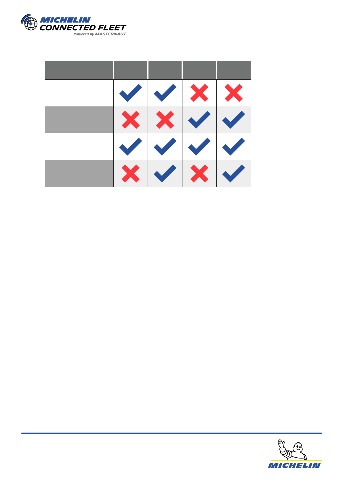
Product Install Guide – M4xx Series
03/11/22 | V1.9.9
M400 /
M403
M404 /
M405 M410 M414 /
M415
External Antennas
Internal Antennas
GSM
LTE
NOTE: For instructions that do not refer to the full M4xx series will be referred to as follows:
M40x = M400, M403, M404 & M405
M400/3 = M400 & M403
M41x = M410, M414 & M415
4. M4xx versions

7
Product Install Guide – M4xx Series
03/11/22 | V1.9.9
Power Loom
070196
Security Seal
071211
GPS 040215
(M400/3)
GSM 040101
(M400/3)
GPS/GSM 040303
(M400/3)
SCN4 CAN #1
White Label 030433
SCN4 CAN/J1587 #2
Green Label 030438
HMI Sustainability+
031118
Kline + D8 Interface
030637
D8 Cable
030628
Kline Cable
030628
Gritter Cable Serial
030920/030909
4RS232 Adapter
030627
Gritter Cable XLR
030913
GSM/LTE 040112
(M404 / M405)
Tachofresh hinterer
CANBUS 030631
Tachofresh & Gritter Parts
5. Parts
CAN
GPS
GSM/GPRS
Default
Init
M4xx
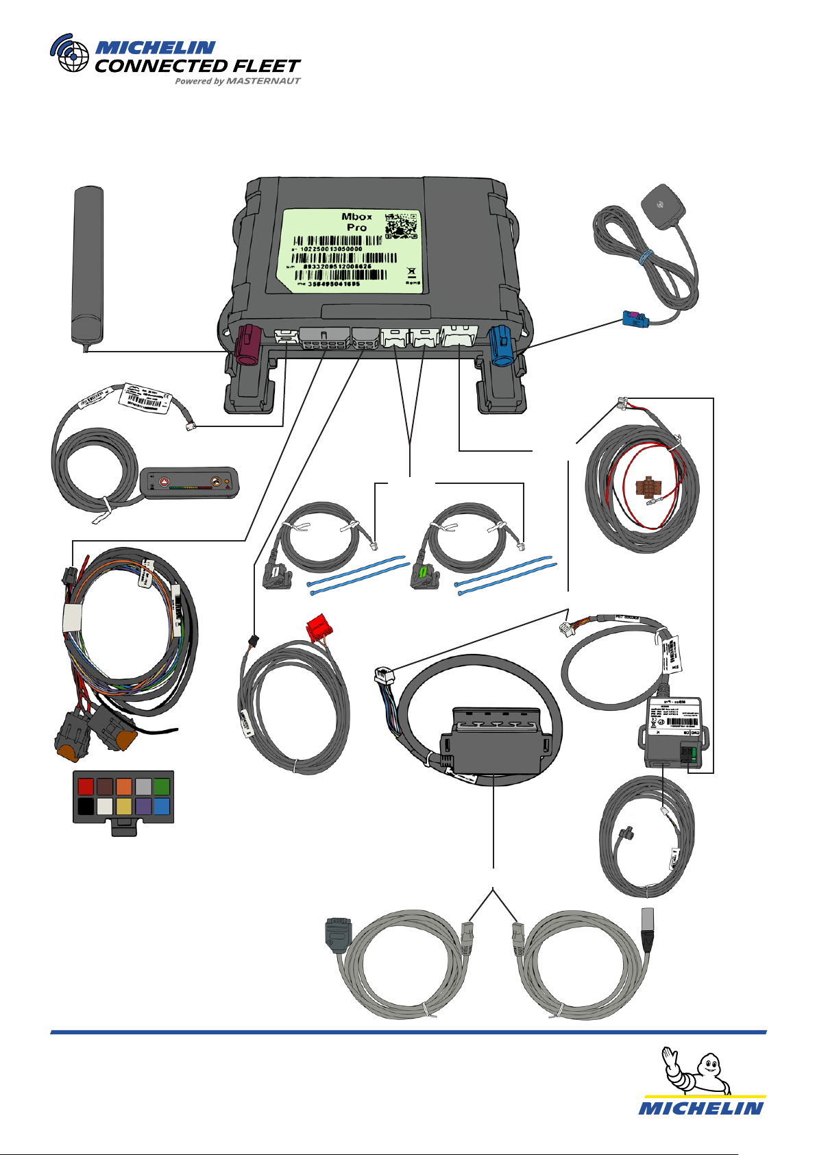
8
Product Install Guide – M4xx Series
03/11/22 | V1.9.9
K-LINE + D8
INTERFACE
OR
OR
OR
OR
1. Power (+) - 5A Fused
2. Ground (-)
3. Ignition (+) - 5A Fused
4. Input 2
5. Input 3
6. Input 4
7. Analog 1
8. Analog 2
9. Output 1
10. Output 2
4RS232
ADAPTER
POWER
LOOM
GRITTER
INTERFACE
(SERIAL)
GRITTER
INTERFACE
(XLR)
HMI
6. Wiring Diagram
108642
97531
M40x
GPS
GSM:
M400/3
GSM/LTE:
M404/M405
CAN J1587
D8
K-LINE
CAN
TACHO
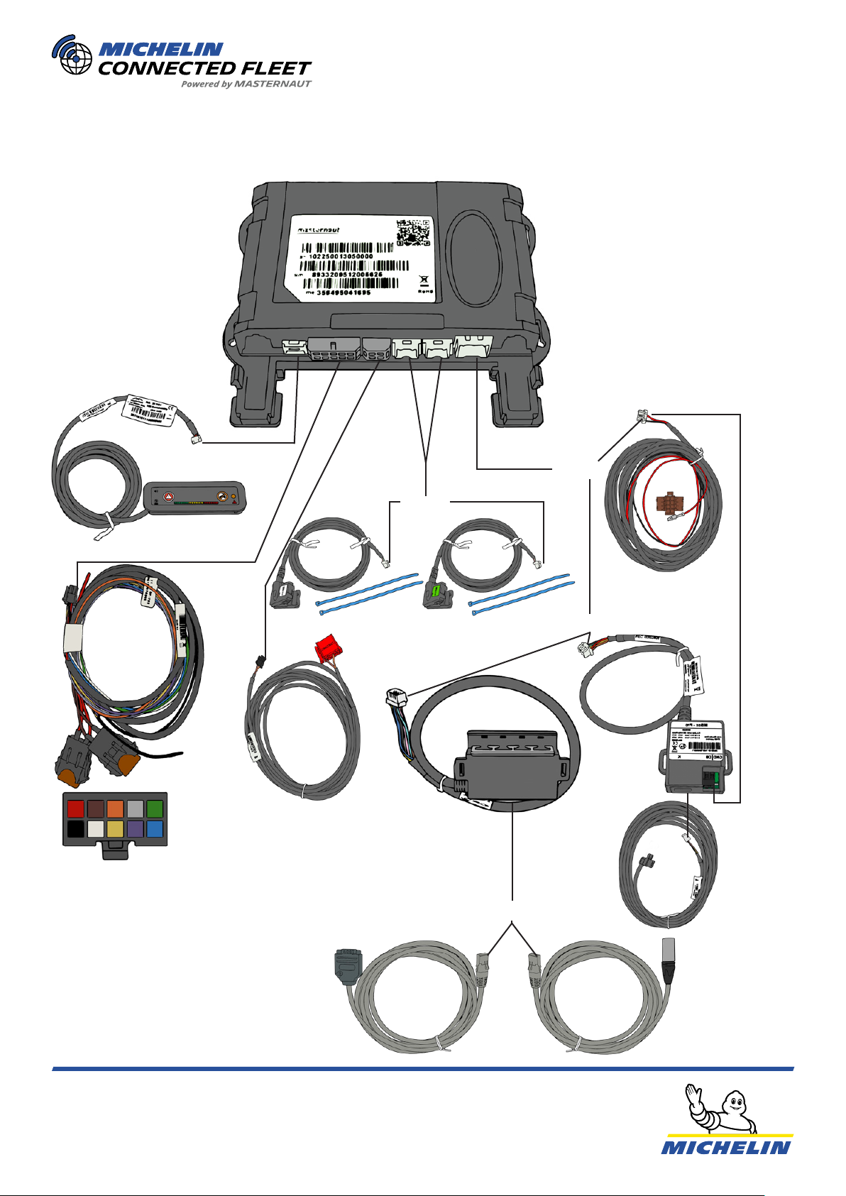
9
Product Install Guide – M4xx Series
03/11/22 | V1.9.9
K-LINE + D8
INTERFACE
OR
OR
OR
OR
1. Power (+) - 5A Fused
2. Ground (-)
3. Ignition (+) - 5A Fused
4. Input 2
5. Input 3
6. Input 4
7. Analog 1
8. Analog 2
9. Output 1
10. Output 2
4RS232
ADAPTER
POWER
LOOM
GRITTER
INTERFACE
(SERIAL)
GRITTER
INTERFACE
(XLR)
HMI
7. Wiring Diagram
108642
97531
M41x
CAN J1587
D8
K-LINE
CAN
TACHO
10
Product Install Guide – M4xx Series
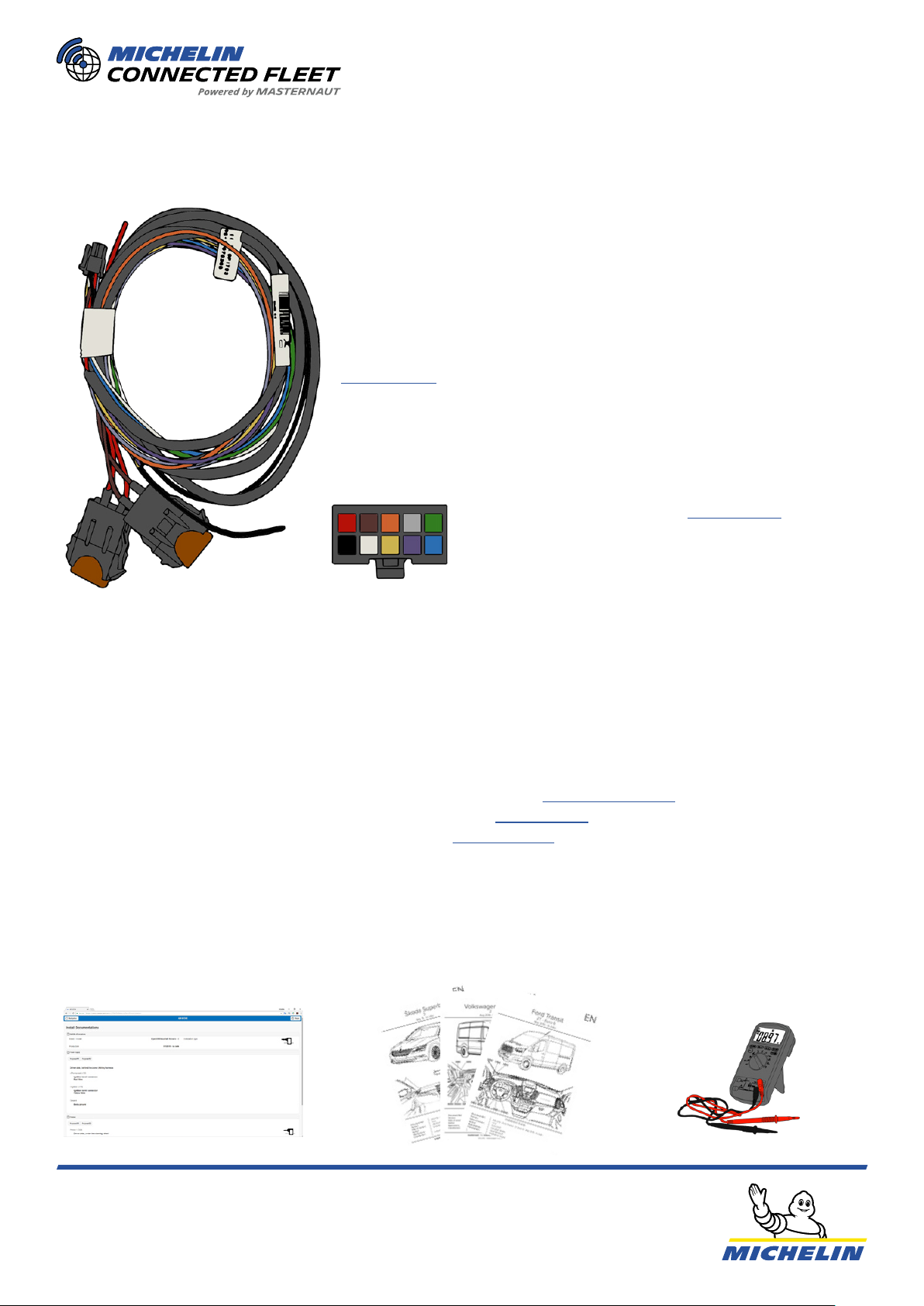
03/11/22 | V1.9.9
Permanent power supply feed (12/24V-DC)
- Provides Power to the system. Must be tted after circuit breaker
(if available).
Main Loom
Power (+) - RED
Ground (-) - BLACK
Ignition(+) - BROWN
POWER I/O CONNECTOR
Input/Output (see page 22)
Input 2 - WHITE
Input 3 - ORANGE
Input - YELLOW
Analog 1 - GREY
Analog 2 - PURPLE
Output 1 - GREEN
Output 2 - BLUE
Always refer and follow MICHELIN Connected Fleet’s recommendedPower (+), Ignition(+), and
Ground(-) connection points for the vehicle you are working on.
The recommended connection points are available:
• In the Vehicle guides, available on your job on Salesforce (Salesforce Guide)
• On the Master Manager Mobile (MMO) Install page (MMO guide)
• In the CAN-database, available through MMO (Link to MMO)
NOTE:
ALWAYS double check your connections with a multimeter as colours or wiring may change.
ALWAYS position the 5A fuses on the fused connections, power and ignition, as near to the
connection point as possible (do not extend the fuse wires).
ALWAYS connect the power supply to the feed rst and then to the OBU, to avoid electrical primers.
+POWER
Ignition Feed (12/24 V-DC)
- Must be connected to the ignition (2nd stage, still ON when
engine is running) and NEVER to the true engine idling feed (which
is only ON when engine is running).
(See page 10)
+IGNITION
- Must be connected directly to the chassis or a ground terminal.
NEVER use a self-tapping screw for a ground connection.
GROUND
VEHICLE SPECIFICS
7. Power Supply

11
Product Install Guide – M4xx Series
03/11/22 | V1.9.9
12 Vdc on
multimeter**
It is important to dierentiate between the rst (accessories) stage and second (ignition) stage.
You have to make sure that you connect the ignition wire to a second (ignition) stage ignition feed. If
connected to the rst (accessories) stage the data recorded by the M4xx will be wrong, for example
idling.
The ignition feed must also be live when a Stop & Start occurs (engine o at trac lights). The feed
does not have to be live while cranking but it is good practice if it is.
Turn key to 1st stage*Instrument Cluster O 0 Vdc on multimeter
0 Vdc on multimeter
12 Vdc on multimeter
Instrument Cluster On
Instrument Cluster On
Instrument Cluster O
Turn key to 2nd stage
Crank the engine
Stop the engine
**Sometimes the voltage will fall to 0Vdc while the engine is cranking and then returns to 12-14Vdc.
NOTE:
*Some vehicles do not have an accessories stage and the rst position of the barrel is ignition.
8. Ignition

12
Product Install Guide – M4xx Series
03/11/22 | V1.9.9
Strip about 10mm of
the insulation. Twist the wires together. Solder the wires together.
When making multiple
connections on the same loom it
is good practise to space out the
connection points.
Bad practise.Best practise.
Cut and strip the feed wire and
add a piece of heatshrink.
Line up the wires in the
crimping terminal Crimp the wires together
Heat the heatshrink and wrap
with insulating tape to insulate
and waterproof the
connection point.
When making multiple
connections on the same loom it
is good practise to space out the
connection points.
Bad practise.Best practise.
Prior to cutting and crimping any cables you MUST make sure
that the ignition is turned o, also double check the wire with a
multimeter.
9. Soldering Method
10. Crimping Terminal Method
12 3
4
123
4
Insulate and waterproof the
connection with electrical and
amalgamiting tape/heat shrink.
13
Product Install Guide – M4xx Series
03/11/22 | V1.9.9
GPSGPS
GSMGSM
15”
40 cm
15”
40 cm
15” 40 cm
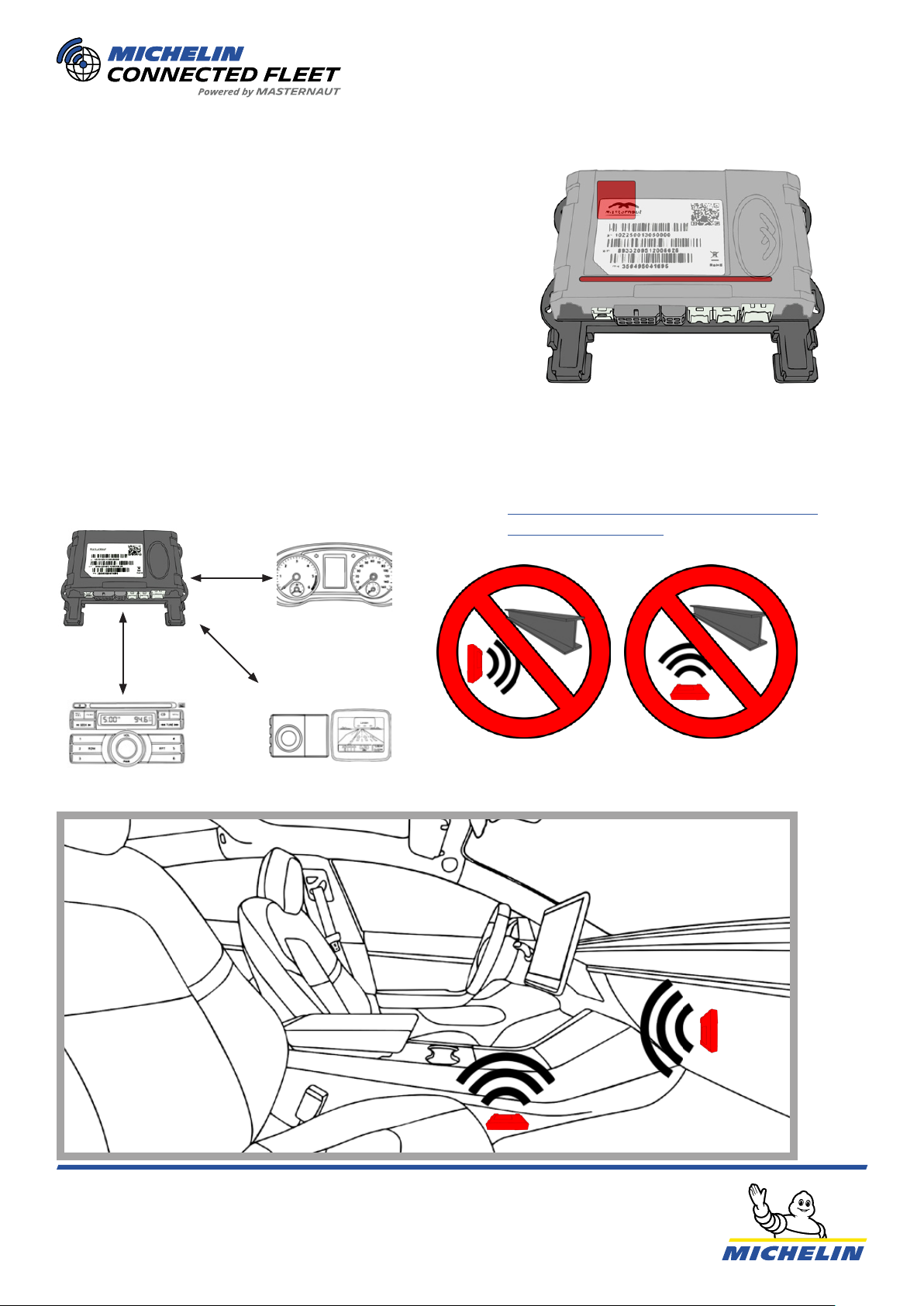
When possible, to reduce interference,
the M41x should be placed atleast
15 inches/40cm) from any electrical
equipment.
INTERFERENCE
The GSM antenna in the M41x is located
internally by the connectors on the side with
the label.
GSM ANTENNA
The GPS antenna in the M41x is located
internally by the LEDs on the side with the
label.
GPS ANTENNA
The M41x, the OBU must NEVER be mounted
behind or beneath any metal structures. This
will obstruct the antennas.
The side with the label should always face up
or towards the inside of the vehicle. See below
illustration.
POSITIONING GUIDELINES
Click here for the M41x recommended
positions appendix.
Internal antennas (M41x)
11. Antennas

14
Product Install Guide – M4xx Series
03/11/22 | V1.9.9
Mercedes-Benz Trucks Actros & Arocs (MP4)
Iveco Daily (Euro 6)
Citroen Jumper/Relay & Fiat Ducato & Peugeot Boxer
Renault Master 3 & Vauxhall/Opel Movano 2
Scania R (Passenger side)
Fiat Doblo (2)
POSITIONING EXAMPLES
NOTE: The M41x must be installed behind the dash trim of the vehicle and not accessible to the end
user (driver).
12. Antennas

15
Product Install Guide – M4xx Series
03/11/22 | V1.9.9
GSM & GSM/LTE Antenna (M40x)
To reduce interference the GSM & GSM/LTE antennas
MUST be placed atleast 7.87 inches (20cm) from the
GPS antenna and any electrical equipment. It must
also be placed atleast 1.2 inches (3 cm) from any metal
in the vehicle.
GPS Antenna (M40x)
To reduce interference
the GPS antenna
MUST be placed
atleast 7.87 inches
(20cm) from the GSM
antenna.
Use the included
double sided tape and
a piece of reinforced
tape on top to x the
antenna in position.
The antenna also has
a magnet to hold it in
place if you are tting
it to metal.
The GPS antenna is tted under the dash or
on the a-pillar, with a clear line of sight to the
sky. See §“GSM, GSM/LTE & GPS positions
(M40x)” on page16 for examples.
The MICHELIN Connected Fleet logo on the
GPS antenna must face the sky, see below.
There is also an arrow on the side indicating
the way it must face.
There can be no metal obstructing the line of
sight of the GPS antenna.
The side with the
antenna symbol
must be facing the
sky.
INTERFERENCE
POSITIONING AND MOUNTING
INTERFERENCE
MOUNTING
POSITIONING
The GSM & GSM/LTE antennas is installed covertly, but it can
also be
installed overtly on the windscreen. See examples §“GSM, GSM/
LTE & GPS positions (M40x)” on page16.
When installing the GSM & GSM/LTE antennas covertly you t it behind a panel
or the dash, see the vehicle specic guide for positions. Fix the antenna in
position with the reinforced tape.
If you are installing the GSM & GSM/LTE antennas overtly on a thermal
windscreen, with a dotted area, make sure you are tting it on the non-thermal,
dotted, area. See §“GSM, GSM/LTE & GPS positions (M40x)” on page16. If you
are installing it overtly on a classic windscreen t it behind the rear view mirror
in one of the bottom corners. See §“GSM, GSM/LTE & GPS positions (M40x)” on
page16.
12. Antennas
7.87” 20 cm
20 cm
7.87”
7.87” 20 cm
This manual suits for next models
9
Table of contents
Other Michelin Automobile Accessories manuals


