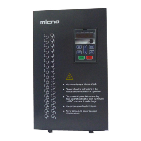
Micno HE1000 Series User manual

Customer Service Hotline
Drive the Future with Intelligent Drives
Shenzhen Micno Electric Co., Ltd.
Address: 4th Floor, Building 1, Invengo RFID Industrial
Park, Tongguan Road, Jiazitang, Guangming District,
Shenzhen, China
Zip code: 518108
Tel: 0755-21675219
Fax: 0755-21675200
Email: [email protected]
Website: www.micno.com.cn
i·Drive
400-
861
-
8111
UMHE1000 2017-BO1
English
Shenzhen Micno Electric Co., Ltd. 2017 All Rights Reserved

HE1000 Series High Voltage Frequency Inverter
System Control Program
Stock code: 839477

Contents
Overview ........................................................................................................................................................1
Compatibility...........................................................................................................................................1
Safety Notes ............................................................................................................................................1
Intended Audience...................................................................................................................................1
Manual Content.............................................................................................................................................2
Startup............................................................................................................................................................3
How to Start the Frequency Inverter.......................................................................................................3
First Startup Procedure............................................................................................................................3
Line Inspection Before Startup................................................................................................................4
Control Power-up....................................................................................................................................4
High Voltage Power-up ...........................................................................................................................5
Operation without the motor ...................................................................................................................6
Operation with the motor ........................................................................................................................7
Man-Machine Interface................................................................................................................................8
Overview of Man-Machine Interface......................................................................................................8
Main Interface.........................................................................................................................................9
System Account Area ......................................................................................................................9
Real-time Data Area........................................................................................................................9
Operation Area ..............................................................................................................................10
Real-time Alarm Area....................................................................................................................12
MenuArea.....................................................................................................................................12
System Management.............................................................................................................................13
System Settings.....................................................................................................................................15

1
Operation Configuration................................................................................................................15
Torque Optimization Configuration..............................................................................................17
Protection Configuration...............................................................................................................19
Alarm Configuration .....................................................................................................................20
Delivery Configuration..................................................................................................................21
Parameter Settings.................................................................................................................................22
Motor Parameters..........................................................................................................................23
Control and Giving Parameters.....................................................................................................26
PID Parameters..............................................................................................................................29
Multistage Speed Parameters ........................................................................................................29
Analog Input and Output...............................................................................................................30
Other Parameters...........................................................................................................................31
Saving and Firming...............................................................................................................................32
Operation Record ..................................................................................................................................33
Operation Information...................................................................................................................33
Unit Bypass State..........................................................................................................................34
I/O State.........................................................................................................................................34
Historical Data...............................................................................................................................35
English/Chinese Switch.........................................................................................................................35
Real-time Monitoring............................................................................................................................35
Application Description..............................................................................................................................36
Local Control.........................................................................................................................................36
Remote Control.....................................................................................................................................36
Factory Control Macro..................................................................................................................37
Three-Wire System Macro ............................................................................................................39

2
Manual and Automatic Control Macro..........................................................................................41
Multistage Speed Macro................................................................................................................43
Electric Potentiometer Macro........................................................................................................44
PID Closed-Loop Control Macro..................................................................................................45
Secondary Output Terminal Wiring Diagram of the HE1000 ........................................................46
Field Bus.......................................................................................................................................................47
Communication Description..................................................................................................................47
Communication Address and Description.............................................................................................48
Communication Application..................................................................................................................55
Special FunctionApplications....................................................................................................................56
Rotation Speed Tracking Function........................................................................................................56
Start After Braking................................................................................................................................58
Rapid Frequency Drop ..........................................................................................................................59
Adjustment of Acceleration and Deceleration Time Polylines..............................................................61
Troubleshooting and Maintenance ............................................................................................................63
Minor Fault Classification and Alarms..................................................................................................63
Major Fault Classification and Alarms..................................................................................................63
Common Troubleshooting.....................................................................................................................63
Power Unit Replacement.......................................................................................................................65
Maintenance..........................................................................................................................................66

HE1000 System Control Program
Overview
About This Chapter
This chapter covers the manual content introduction and information about compatibility, safety and intended
audience.
Compatibility
This manual is applicable to CPU V2.6 and later versions of the HE1000 high voltage frequency inverter.
This manual is applicable to HMI V2.8 and later versions of the HE1000 high voltage frequency inverter.
Safety Notes
The HE1000 is a high voltage electrical device, misuse of which causes possible physical injuries or
property loss. Be sure to completely follow the instructions in this manual for commissioning.
Only professional electrical personnel are allowed to operate the HE1000 high voltage frequency inverter.
When the frequency inverter trips due to a failure, operators need to be able to determine whether to power
off the HE1000 high voltage frequency inverter for overhaul or conduct fault resetting to bring the
frequency inverter into service again.
Be sure to follow this manual to perform operations and commissioning on the HE1000 frequency inverter.
Failure of following this manual leads to possible physical injuries and abnormal operations of the
frequency inverter, motor and driving device due to damage. Read this manual carefully before performing
any operation on the HE1000 high voltage frequency inverter.
We will provide some technical training for the personnel involved in installation, commissioning,
operation and repair of the HE1000 high voltage frequency inverter and ensure that every person of interest
thoroughly studies and understands the safety content in this manual.
Intended Audience
This manual is intended for persons having actual experience of standard electrical wiring and basic
knowledge of identifying electronic components and the symbols on electrical schematic diagrams.
1

Manual Content
This manual includes the following chapters:
1 Overview
2 Manual Content
3 Startup
4 Man-Machine Interface
5 Application Description
6 Field Bus
7 Special Function Applications
8 Troubleshooting and Maintenance
Product and Consulting Service
If you have any question about our products, please contact local MICNO office.
Product Training
For product training information about the HE1000 frequency inverter, visit MICNO
website www.micno.com.cn.
Please provide you feedback on this manual.
Your evaluation of our product manual is welcome. Send your comments and suggestions to Email:
2

Startup
About This Chapter
This chapter introduces the basic startup procedure of the HE1000 high voltage frequency inverter.
How to Start the Frequency Inverter
You can start the HE1000 highvoltage frequency inverter by using either of the following ways:
Local control (HMI or the start-stop button on the panel of the control cabinet door)
Using the I/O terminal or field bus interface for remote control.
Before starting the HE1000 frequency inverter for the first time, you need to enter basic parameters of
the HE1000 frequency inverter, such as motor data. After the first startup is completed, you can power
up the frequency inverter directly, without repeating the steps such as parameter entry.
If a fault occurs or an alarm is generated during startup, refer to troubleshooting related chapters. When a
major problem occurs, disconnect the device from main power supply and wait 20 minutes for the capacitor
of intermediate circuit to discharge, and check the connection between frequency inverter output and motor
cable.
Note: Aqualified electrical engineer is required to conduct the startup.
For installation inspection, refer to corresponding installation part of the hardware manual.
Ensure that the motor startup does not lead to any danger. For first startup, you need to judge the motor
rotation direction and keep the motor and the driven device mechanically unconnected.
For basic parameter entry,refer to the man-machine interface chapter. For variable frequency startup, refer
to the application description chapter.
First Startup Procedure
Line inspection before startup
Control power-up and parameter settings
High voltage power-up and fan rotation direction inspection, covering the fan on cabinet top and the fan at
transformer bottom
Operation without the motor
3

4
Operation with the motor
Line Inspection Before Startup
After HE1000 installation and wiring (all wiring is done except the connection between the
frequency inverter output and the motor), power up the frequency inverter for commissioning and
then start the frequency inverter for operation. Before operation, you should conduct inspection
carefully, find out and solve problems in time. The following are main check items:
1) Check whether various anchor screws are tightened and whether the routing in the cable trench is
unhindered.
2) Check whether the circuits, especially the main circuit, are correctly connected and whether the
grounding terminal is well grounded.
3) Check whether all unit power supplies in the unit cabinet are corresponding and correctly
connected with the secondary windings of the transformer one to one.
4) Check whether shielded cables are used for the external DCS control circuit and whether the
shielding layer is well grounded.
5) Check whether the optical cable connection between the main control board and the power unit is
correct, and whether loose connection or deformation occurs.
6) Confirm that no connection terminals or wires are shorted out and no grounding short circuits
exist.
7) Check all screws and wiring terminals to ensure the connections are secured.
8) Check whether wire scraps, screws or tools are scattered inside the frequency inverter or,
especially, on the transformer.
9) Check whether the cabinet and doors are reliably grounded.
10) Check whether the unit cabinet is wind tight so as to guarantee maximum heat dissipation
efficiency.
Control Power-up
1) Before control power-up, confirm that the main control power in the frequency inverter control
cabinet is switched off.
2) Power the device with 220 V control power supply.

5
3) Use a multimeter to check whether the input voltage of the factory distribution terminal in front
of the power switch is normal.
4) Switch on power supply to power up the interface control board and the temperature controller
for the transformer, and then power up HMI. After about one minute, HMI automatically starts up,
completes initialization and shows the system monitoring interface.
5) Observe HMI for fault alarms and check whether the communication between man-machine
interface and PLC is normal. If no, a communication failure error is reported.
6) For parameter settings, refer to the "Man-Machine Interface" chapter.
7) Check whether the display of the temperature controller on the transformer cabinet is normal.
8) Check whether you can switch off the high voltage breaker properly by pressing the emergency
stop button on the unit control cabinet. Repeat the operation three times and ensure that the high
voltage breaker can be reliably switched off every time.
High Voltage Power-up
The high voltage power can be supplied only after you ensure that all of the above preparations are correct.
Before high voltage power-up, no one is allowed to be close to the frequency inverter cabinet. After high
voltage power-up without abnormality, only operators are allowed to be close to the frequency inverter
cabinet.
1) Keep the transformer cabinet door open and check whether any frequency inverter alarm is
generated or any frequency inverter fault occurs. At this time, the alarm of cabinet door open can
be ignored.
2) Keep all people away from the frequency inverter cabinet.
3) Switch on the high voltage breaker to supply high voltage power to the frequency inverter.
4) Observe whether the fan on frequency inverter cabinet top and the fan at transformer cabinet
bottom both operate normally without abnormal noise. If either or neither of the fans operate,
switch off the high voltage breaker to stop supplying high voltage power to the frequency inverter,
and then conduct circuit check on the fan part, for example, whether the air switch controlling a
fan is off and whether the connection between the fan and the wiring terminal box is loose. If
abnormal noise can be heard, also stop supplying high voltage power to the frequency inverter,
find out and deal with the abnormal noise source.

6
5) After you confirm that all fans operate properly, switch off the high voltage breaker to power off
the frequency inverter. At this time, the fan on cabinet top and the fan at transformer bottom both
rotate freely. Determine whether the rotation direction is correct.
The fan at transformer bottom stops rotation more quickly than the fan on cabinet top. Observe
the rotation direction of the fan at transformer bottom first. Wait till the fan at bottom rotates
slowly, and then check whether the fan rotates in the direction of arrow marked on the fan side.
Observe whether the fans on transformer cabinet top and on power unit cabinet top rotate in the
same direction and whether the direction is proper. To do this, after the rotation slows down,
check whether the fan rotates in the direction of arrow marked on the fan housing.
If the fan rotation direction is abnormal, you should adjust the circuit. Supply high voltage power
to the device again and then power off the device for correction.
6) Close all cabinet doors and supply high voltage power to the frequency inverter again. Hold a
piece of A4 paper near every air inlet, and see whether the paper can snap to the cabinet door. If
the paper snaps to the cabinet door closely, the fan rotation direction is correct and the ventilation
path is unimpeded. If the paper does not snap to the cabinet door closely, the fan stops rotating or
rotates in reverse direction or the air path is impeded.
7) Observe whether all status indicators on main control board inside the control cabinet are green,
which is normal.
Note: When you observe the rotation direction of the fan at transformer cabinet bottom, do not touch
the transformer.
Operation without the motor
1) Select local control.
2) Set the frequency to 5 Hz.
3) Use the man-machine interface or the local start button on the cabinet door to start the device.
4) Check whether the output voltages are correct respectively.
5) Increase the frequency by 5 Hz every time and view the output until the operation starts at 50 Hz.
6) Use the man-machine interface or the local stop button on the cabinet door to shut down the
device, and observe whether the device is normal.
7) Set the frequency to 50 Hz, restart the device, and observe whether the device can properly start
at 50 Hz.

7
8) Shut down the device.
Operation with the motor
1) Keep high voltage off and connect the frequency inverter output to the motor cable.
2) Before operation, check whether the load is in safe state which allows operation and whether the
ventilation door and valve are properly closed or opened.
3) Select local control.
4) Set the frequency to 5 Hz.
5) Supply high voltage power to the device.
6) Use the man-machine interface or the local start button on the cabinet door to start the device.
7) Check whether the motor rotation direction is correct. If no, shut down the device, switch off the
high voltage power supply, readjust the main circuit wiring, and follow Step 1 – 6 again to start
the motor.
8) View whether the output voltage and the output current on each of three phases are correct and
whether the currents on three phases are balanced.
9) Increase the frequency by 5 Hz every time and view the output voltage and current until the
operation starts at 50 Hz.
10) During acceleration, check whether motor vibration or load swing occurs. If yes, keep a record,
set the hopping frequency after shutdown, and avoid operation at corresponding speed.
11) When the given frequency turns into 5 Hz from 50 Hz, observe whether the deceleration process
is normal. Otherwise, adjust parameter settings after shutdown, such as deceleration time.
12) Use the man-machine interface or the local stop button on the cabinet door to stop the device.

8
Man-Machine Interface
About This Chapter
This chapter introduces how to use the Man-Machine Interface (HMI) component of HE1000 high
voltage frequency inverter. This component can be used to control the frequency inverter, read status
data, search and modify parameters.
Overview of Man-Machine Interface
A 10-inch man-machine interface for the HE1000 high voltage frequency inverter is installed on the
right side of the control cabinet. The user interface is built on Windows CE and all operations on the
frequency inverter can be completed on this interface. In order to guarantee operation security, only
authorized operators are allowed to access and modify the parameters.
During touch operation, touch the screen lightly with finger-end, instead of knocking the screen with hard
objects such as fingernail, to avoid scratching the touch screen.
During system power-up, the HE1000 high voltage frequency inverter automatically displays the HMI.
1) With expressions in both English and Chinese as well as graphic signs, the man-machine
interface is easy to learn and use.
2) The large screen display allows setting a set or several sets of parameters accurately, intuitively
and easily at the same time, without tedious parameter code numbers.
3) The operating parameters are displayed on the same screen and can be viewed completely at one
glance.
4) The status is displayed.
5) Important operation data is recorded and can be queried.
6) The fault history can be recorded, saved and queried by date, and the fault alarms can be
exported.

9
Main Interface
During system power-up, the HE1000 high voltage frequencyinverter automatically displays the HMI.
The following figure shows the startup screen.
Login Account
System Management
System Settings
Parameter Settings
Saving and Firming
Operation Record
Realtime
Monitoring
The display screen can be touched only by operators.
Operation
Frequency
Average
Current
Control Mode
Motor Rotation
Direction
Local
None
Given Frequency
Output Voltage
Status
Giving source
Stop
Local
Date Time Object Name Current Value Alarm Description
High Voltage Power Down
System Account Area
This area displays the current login account name as well as the data and time of HMI operating system.
Real-time Data Area
This area displays the real-time status of the frequency inverter, including operation frequency, given
frequency, currents on three phases (including the average current), output voltage, control mode, operation
state, motor rotation direction, and giving source.
(1) Operation frequency: actual output frequency of the frequency inverter.
(2) Given frequency: given frequency value. In local mode, the given frequency is the value set on the
frequency setting panel in the operation area. In remote mode, the given frequency is given value of
remote mode. When the remote analog quantity is given, 4-20 mA or 0-20 mA is corresponding to the
engineering coversion value at 0-50 Hz. When the device is set from remote mode to local mode, the
given value becomes the local given value set on the frequency setting panel in the operation area.
When the given frequency value is less than the lower frequency limit set on the system or larger than
the upper frequency limit set on the system, the given frequency value automatically defines the upper
frequency limit or lower frequency limit.

10
(3) Currents on three phases (including the average current): values of currents on three phases during
frequency inverter operation. You can set as phase A current, phase B current, phase C current, or their
average current.
(4) Output voltage: value of actual voltage output by the frequency inverter.
(5) Control mode: local/remote control mode set by users.
(6) Operation state: operation/stop state of the frequency inverter.
(7) Motor rotation direction: clockwise/counterclockwise rotation state of the motor during frequency
inverter operation.
(8) Giving source: giving source of the frequency inverter, for example, local, AI1, AI2 and bus
communication.
Operation Area
The operation area is the operation panel for controlling the frequency inverter locally, including five touch
operation buttons: local operation start, local operation stop, local rotation direction setting, local frequency
giving and local major fault reset.
(1) Local operation start :
to start frequency inverter operation in local mode. After the frequency inverter is started, the motor
accelerates to the current set frequency based on preset acceleration slope (acceleration time). The motor
acceleration time is determined by the acceleration time constant.
(2) Local operation stop :
to stop frequency inverter operation in local mode. The frequency inverter stops in the preset stop mode.
The stop mode is divided into free stop and decelerative stop. When you set the frequency inverter to be in
free stop mode, the frequency inverter immediately blocks the output. When you set the frequency inverter
to be in decelerative stop mode, the frequency inverter drags the motor to decelerate to near 0 Hz and then
blocks the output. The deceleration time is determined by the deceleration time constant.

11
(3) Local rotation direction setting :
To preset the motor rotation direction in local mode. Select whether the motor operates clockwise or
counterclockwise. When the value of clockwise and counterclockwise rotation protection is set to 2 (only
counterclockwise rotation is available), the selection of clockwise rotation is invalid. When the value of
clockwise and counterclockwise rotation protection is set to 1 (only clockwise rotation is available), the
selection of counterclockwise rotation is invalid.
Note: when you change the rotation direction setting, ensure that the frequency inverter is in stop state. The
remote rotation direction is determined by the selected control macro. Please refer to related content in the
"Application Description" chapter.
(4) Local frequency giving :
To pop up the panel of local frequency giving and set the local given frequency. In local mode, the giving is
determined by the set value on the panel of local frequency giving. In remote mode, if the selected giving
source is the parameter data of "Local Giving", frequency inverter giving is also determined by the set
value on the panel of local frequency giving. When the entered frequency value is less than the lower
frequency limit or larger than upper frequency limit, the given frequency value is automatically set to the
upper frequency limit or lower frequency limit. The following figure shows the panel of local frequency
giving.
How to operate the panel of local frequency giving: Click the digit position where the cursor is, as shown in
the above figure. After the system pops up a data entry box, directly enter a given frequency value, and then
click ENTER for final setting. The four buttons below ENTER are used to quickly/slowly

12
increase/decrease the given frequency. After increasing or decreasing the given value, you need to press
ENTER for final setting.
(5) Local major fault reset :
To reset a major fault and clear the major fault holding signal of the system. You can also conduct reset by
using the Reset button on the cabinet door. If you click this button when the reset is completed or no major
fault occurs, the prompt of "No Major Faults" appears, as shown in the following figure.
No Major Fault
Close
Real-time Alarm Area
The real-time alarm area is at the bottom of the HMI, including state alarms such as frequency inverter in
operation, frequency inverter stop and high voltage power-down, as well as bypass signal alarms for each
unit of the frequency inverter. Users can easily view the real-time operating state of the frequency inverter.
Menu Area
The main menu in the menu area includes five parts: system management, system settings, parameter
setting, saving and firming, operation record and English-Chinese switch, by which you can set frequency
inverter functions, protection and parameters. Before performing any menu operation, you need to log in to
the system with related permission. The following figure shows the main menu screen.

13
System Management
System Settings
Parameter Settings
Saving and Firming
Operation Record
System Management
The system management includes User Login,Change Password and User Logout, as shown in the
following figure.
User Login
Change Password
User Logout
Return

14
(1) User Login:
The users set for logging in to the frequency inverter include Operator1, Operator2, Admin, and CMK.
CMK is the account for commissioning before delivery and involves the entry of some delivery
configuration information. This account is used by the delivery commissioning personnel only.
Click User Login, and the system pops up a user selection box. Select the account for login, and then enter
the login password to log in to the system with selected account. If you log in for the first time or the
account password is not set, directly click Confirm in the popped up selection window. After login, Login
Account on top left of the man-machine interface displays the current login account.
The Admin account has all system privileges, capable of modifying system settings and system parameters,
while Operator1 and Operator2 can only query alarm information and operation data permission.
(2) Change Password: to change the login password of the login user.
Click Change Password, and the window for changing the password of current login user pops up. After
entering the old password and new password, click Confirm in the popped up window to complete
changing this account password.
If no account logs in to the system currently, the system pops up the prompt of "No Login Account
Currently".
(3) User Logout: to log an account out of the system. None is displayed for login account.
Note: The default password of any account is blank before delivery, except the CMK commissioning
account.

15
System Settings
The system settings menu includes operation configuration, torque optimization configuration, protection
configuration, alarm configuration and delivery configuration. You need to log in to the system with an
account with administration privileges to modify key parameters. The following figure shows the system
setting menu.
Operation Configuration
Torque Optimization
Configuration
Protection Configuration
Alarm Configuration
Delivery Configuration
Return
Operation Configuration
Automatic Major Fault Reset
Self-Start After Short Time High Voltage
Down
Permissible High Voltage Power Down
Time
Frequency Inverter Operation Mode
Rotation Speed Tracking Function
Frequency Inverter Start Mode
Braking Time on Startup
Frequency Inverter Stop Mode
Frequency for Decelerative Stop and Free
Stop
Forbid
Disable
Normal Operation
General Startup
Free Stop
Close
Disable
Table of contents
Other Micno Inverter manuals