BTS 65, GB
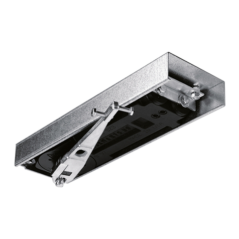
The practical clamp fixing
system of the DORMA
BTS 65 ensures a secure
and high-precision fit in the
cement box.
The adjustment range in the
cement box is as follows:
Transverse 9 mm
Longitudinal 8 mm
Vertical 6 mm
Applications and installation
1Valve for 130° – 0° closing
speed adjustment
2Valve for increasing the
130° – 20° closing speed
Applications and fixing
instructions, door straps and
top centres
See Technical Information
“Floor spring accessories
DORMA BTS”.
DORMA 2300 Sealing
Compound
For filling the cavities
between the floor spring
body and the cement box to
prevent moisture penetration
(mandatory according to
e.g. VOB regulations for wet
rooms).
Spindle inserts
The floor clearance can be
adjusted as required by sim-
ply replacing the insertion
spindle with another size.
Special spindle designs
available on request – e.g.
wide flats with 3° offset,
square and spindle inserts
for non-DORMA-specific
accessories.
Universal cover plate
Available in stainless steel
or satin brass.
Accessories
Calculating the necessary length of spindle extension:
Extension = X – Floor clearance (normally 8 mm)
Collar height Z of the extended spindle inserts = Spindle
extension length + 3 mm (collar height of the standard
spindle insert)
Specification text
Floor spring for double
action doors, with hydraulic
fully controlled closing from
approx. 130°; including
cement box and removeable
spindle insert.
Size
YEN 3
YEN 4
Models
YStandard
YHold-open 90°
Accessories
YUniversal cover plate
Y Stainless steel
Y Satin brass
YExtended spindle insert,
. . . mm extended
YSealing compound
Make: DORMA BTS 65
bBTS65
Floor spring Floor spring Extended spindle inserts (extension in mm) Universal cover plate Sealing
BTS 65 including BTS 65 including 5 7,5 10
12,5
15 20 25 28 30 35 40 45 50 compound
cement box and cement box and Stainless Satin 2300
standard without steel brass
spindle insert, spindle insert 0,5 kg
not pre-assembled
46700086 46700186 45090059
Standard
EN 3 EN 3
25030101 25030100 # # # # # # # # # # # # # # # # #
EN 4 EN 4
25040101 25040100 # # # # # # # # # # # # # # # # #
with hold-open 90°
EN 3 EN 3
25130101 25130100 # # # # # # # # # # # # # # # # #
EN 4 EN 4
25140101 25140100 # # # # # # # # # # # # # # # # #
45200401 Normal
45200402
45200403
45200404
45200419
45200405
45200406
45200407
45200414
45200408
45200409
45200410
45200411
45200412
# = Accessory
Options and accessories

