Turning on the Laser
The measuring laser on the sensor is switched on via a software command or a switching input. This allows to switch off the sensor for maintenance purposes or similar. Response time: after the laser
is switched on, the sensor needs depending on the measuring rate five cycles to send correct measured data.
Laser on/off via software,
Supply with PoE
The measuring laser on the sensor is
activated via a software command.
Laser on/off via hardware,
Supply with PoE
The measuring laser on the sensor is activated
via a switch or similar.
Laser on/off via hardware,
Supply without PoE
A switching transistor with open collector (for example in an optocoupler), a relay contact or a digital TTL or
HTL signal are suitable for switching.
Activation using the
PC1900-IE-x/OE-RJ45 cable is pos-
sible.
Activation using the PC1900-IE-x/OE-RJ45 cable is possible.
PC1900-IE-x/OE-RJ45
7
Violet 8
ILD1900-IE
Black
VH
PC1900-IE-x/OE-RJ45
7
1
Violet 8
Type 1 ILD1900-IE
Type 2 Type 3
Black
V+
10k
VH
The inputs are not electrically separated.
24 V logic (HTL): Low level ≤ 3 V;
High level ≥ 8 V (max 30 V)
internal pull-up resistor, an open input is detected
as High.
Max. switching frequency 10 Hz
The ground of the logic circuit must be galvani-
cally connected to "Laser on/off -".
No external resistance is required for current limitation. For permanent "Laser on", connect the black and violet wires.
Switch between EtherCAT Operation and Ethernet Setup Mode
The sensor starts in the last stored operating mode. It is factory set to EtherCAT. Access via Ethernet is possible in the Ethernet setup mode.
Press and hold the Select button on the sensor before switching on the power supply on the sensor. Release the button again as soon as the State LED flashes yellow. Press the button again
for approx. 10 to 15 seconds until the State LED flashes red.
Within the time t2... t3, the red flashing with 8 Hz starts after 10 seconds. The key must be released again after 15 seconds at the latest. When the Select key is released at the latest at time t3, the
State LED starts to flash yellow at 8 Hz.
State LED
Firmware installation or
IE/Ethernet switch
Select key
Supply
voltage
red
yellow, appr. 8 Hzred, 8 Hzyellow flashing appr. 1 Hz yellow green yellow
t0t1t3
t2
10 ... 15 sec
t4
Ethernet Setup Mode
t0: Supply voltage is applied.
t1: The State LED starts flashing yellow, the Select button
can be released
t2: Within 15 sec. (t2 - t1), press Select button again and
hold for further 10 ... 15 sec. (t3 - t2)
t3... t4: Switches from EtherCAT to Ethernet setup mode, duration
max. 1 min.
t4: Sensor starts in Ethernet setup mode, the State LED
lights up briefly at intervals of approx. 1 sec.
Flowchart for starting a sensor in Ethernet setup mode
After completion of the firmware installation/switch, the sensor reboots at time t4.
Switch between Ethernet Setup Mode and EtherCAT
The sensor starts in the last stored operating mode. With the select button, you can set the sensor to the EtherCAT mode.
Press and hold the Select button on the sensor before switching on the power supply on the sensor. Release the button again as soon as the State LED flashes yellow. Press the button again
for approx. 10 to 15 seconds until the State LED flashes red.
Within the time t2... t3, the red flashing with 8 Hz starts after 10 seconds. The key must be released again after 15 seconds at the latest. When the Select key is released at the latest at time t3, the
State LED starts to flash yellow at 8 Hz.
State LED
Firmware installation or
Ethernet/IE switch
Select key
Supply
voltage
redyellow flashing appr. 1 Hz yellow green
t0t1t3
t2
10 ... 15 sec
t4
EtherCAT operation
yellow, appr. 8 Hzred, 8 Hz
t0: Supply voltage is applied
t1: The State LED starts flashing yellow, the Select but-
ton can be released
t2: Within 15 sec. (t2 - t1), press Select button again and
hold for further 10 ... 15 sec. (t3 - t2)
t3... t4: Switches from Ethernet setup mode to EtherCAT, dura-
tion max. 1 min.
t4: Sensor starts in EtherCAT operating mode.
Flowchart for starting a sensor in EtherCAT operation
After completion of the firmware installation/switch, the sensor reboots at time t4.
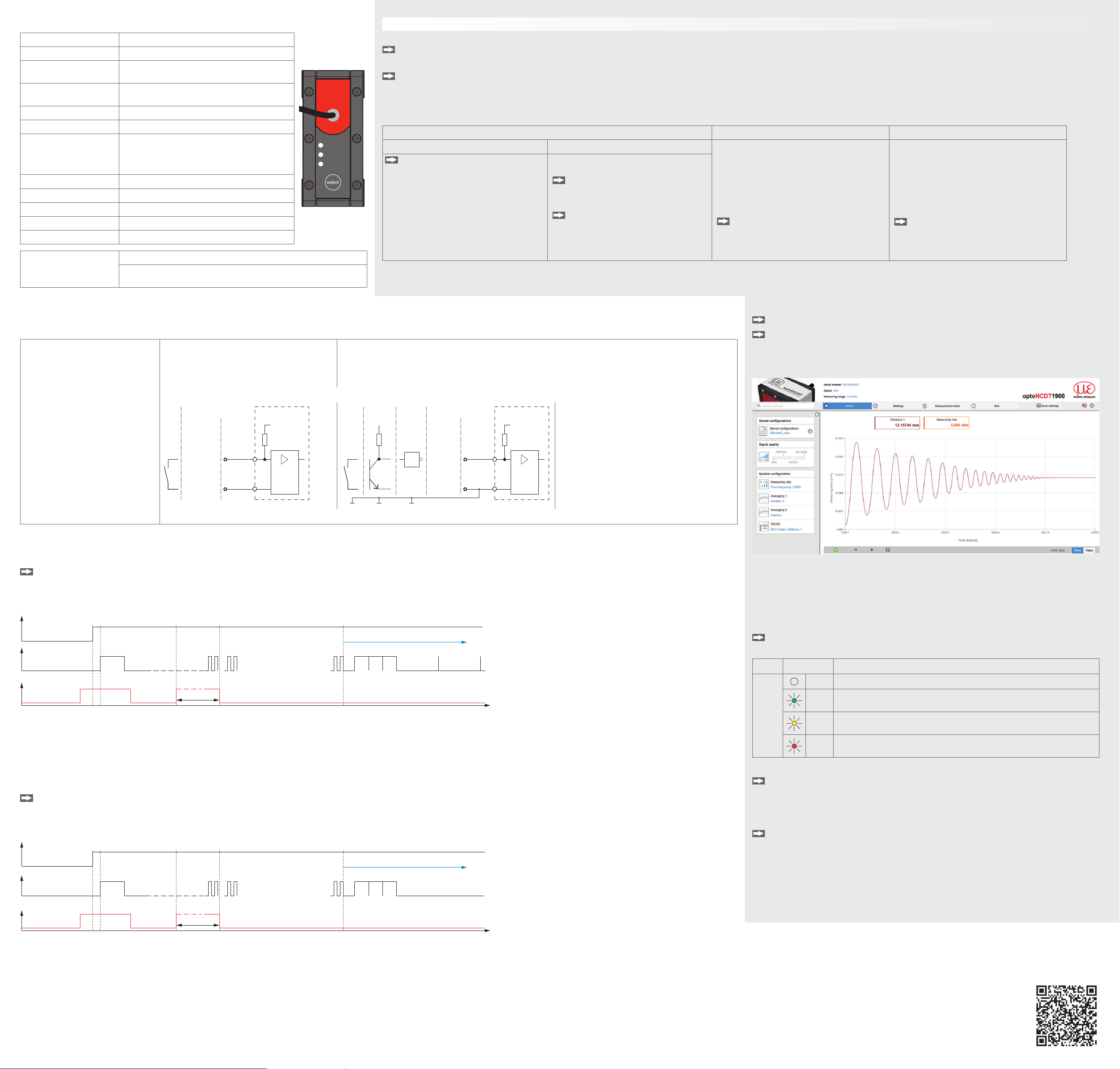
Access via Web Interface
Start your web browser.
Type the IP address of the sensor into the address bar.
Interactive web pages you can use to configure the sensor are now displayed in the web
browser. The web interface does not guarantee real-time measurements. The currently running
measurement can be controlled using the function buttons in the Chart type section.
In the top navigation bar, other functions (settings, measurement chart etc.) are available. The
appearance of the websites can change dependent of the functions. Each page contains dy-
namic parameter descriptions and tips on completing the web page.
After parameterization, store all settings permanently in a parameter set so that they are available
again the next time the sensor is switched on. To do this, use the Save settings button.
Positioning the Target
Position the target as centrally as possible within the measuring range.
The state LED on the sensor indicates the position of the target to the sensor.
LED Color Meaning
state
Off Laser beam is switched off.
Green Measuring object within the measuring range
Yellow Target is in the mid of measuring range.
Red No distance value available, e.g. target outside the measuring range, too
low reflection
Saving the Settings, Continuing Industrial Ethernet Operation
Go to Settings > System settings > Load & Save or click the Save settings
button.
The sensor now also saves the settings for use in Industrial Ethernet operation.
For sensors with operation mode EtherCAT:
Go to Settings > System settings > Boot mode. Select the entry Industrial
Ethernet.
The sensor disconnects from the browser and boots automatically with the Industrial Ethernet
firmware. The boot process can take up to one minute.
Alternatively, you can return to the Industrial Ethernet operation via the select button. Details
can be found in section Switch between Ethernet Setup Mode and EtherCAT.
Continue working in your PLC environment.
Control and Display Elements
State LED Meaning
state
RUN/SF/MS
ERR/BF/NS
Green Measuring object within the measuring range
Yellow Measuring object in the mid of the measuring
range
Red No distance value available, e.g. target outside
the measuring range, too low reflection
Yellow flashing, 1 Hz Bootloader
Yellow flashing, 8 Hz Installation active
State LED lights up
(green, yellow or red) and
briefly flashes yellow at
intervals of approx. 1 sec.
Ethernet setup mode
Off Laser switched off
LED RUN/SF/MS Meaning
depending on Industrial Ethernet operation (IE)
LED ERR/BF/NS Meaning
depending on Industrial Ethernet operation (IE)
Select button Meaning
- Switching operating mode (with EtherCAT only)
- Resetting to factory setting
Quick Guide
Structure of the Components
Mount the sensor and connect the components to one another.
Initial Operation
Connect the sensor to a power supply if PoE is not used.
Operation via Web Interface
The sensors start with the last stored operating mode. Standard is Industrial Ethernet (IE). A web server is implemented in the sensor; the web interface displays, among other things,
the current settings of the sensor. Operation is only possible while there is an Ethernet connection to the sensor.
EtherCAT EtherNet/IP Profinet
Ethernet setup mode Ethernet over EtherCAT (EoE) iAn ILD1900-IE with EtherNet/IP is deliv-
ered in DHCP mode without IP address.
A DHCP server is required, to assign
an temporary IP address to the sensor.
Subsequently, it is also possible to as-
sign a static IP address.
Assign an IP address to the sensor.
You can find an example of this in the appen-
dix of the operating instructions.
iAn ILD1900-IE with Profinet has no IP
address by default. The static IP address
and the device name are assigned
via DCP (Discovery and Configuration
Protocol). The IP address and the device
name can be assigned, e.g., via the TIA
Portal software.
Assign an IP address to the sensor.
You can find an example of this in the appen-
dix of the operating instructions.
Switch to the Ethernet setup mode.
Details can be found in section Switch
between Industrial Ethernet Oper-
ation and Ethernet Setup Mode.
The standard IP address is 169.254.168.150.
Note: As IP setting of the network card
to which the sensor is connected, we
recommend a static configuration with
169.254.168.1 as IP address and the subnet
mask 255.255.0.0.
Parallel to the EtherCAT operation you can
adjust the sensor.
Enable the EoE in your PLC software.
Virtual Ethernet Port is a name in
TwinCAT®.
Assign a MAC address and an IP
address to the slave.
You can find more information about the sensor in the operating instructions.
They are available online at:
https://www.micro-epsilon.com/displacement-position-sensors/laser-sensor/
optoNCDT_1900/?sLang=en
Proper Environment
- Protection class: IP67 (applies only when sensor cable is plugged in)
Lenses are excluded from the protection class. Contamination of the lenses causes impairment
or failure of the function.
- Temperature range - Humidity: 5 ... 95% (non-condensing)
Operation: 0 ... +50 °C - Ambient pressure: Atmospheric pressure
Storage: -20 ... +70 °C


