Ubiquiti USP-RPS User manual
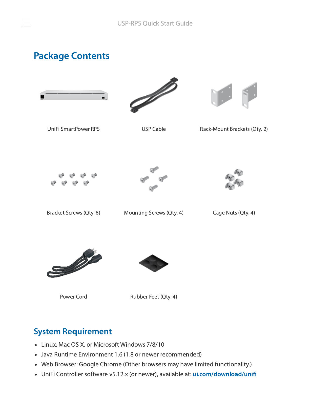
UniFi SmartPower RPS USP Cable Rack-Mount Brackets (Qty. 2)
Bracket Screws (Qty. 8) Mounting Screws (Qty. 4) Cage Nuts (Qty. 4)
Power Cord Rubber Feet (Qty. 4)
Package Contents
System Requirement
Linux, Mac
OS
X, or Microsoft Windows 7/8/10
Java Runtime Environment 1.6 (1.8 or newer recommended)
Web Browser: Google Chrome (Other browsers may have limited functionality.)
UniFi Controller software v5.12.x (or newer), available at:
ui.com/download/unifi
USP-RPS Quick Start Guide

Touchscreen Display
RJ45 Speed/Link/Activity LED
LAN Port
Hardware Overview
Bootup Animation Initializing.
Steady White Factory defaults, waiting for adoption.
Steady Blue Successfully adopted by a network and working
properly.
Location Animation This indicates that you clicked Locate in the UniFi
Controller software. The software will also display the
location of the device on the map.
Off No Link
Green Link Established at 10/100/1000
Mbps
Flashing Indicates Activity
The RJ45 port supports a 10/100/1000 Ethernet connection. Set to DHCP Client by
USP-RPS Quick Start Guide

Reset Button
USP RPS LED (Ports 1 - 6)
USP Connect DC Output (Ports 1 - 6)
Power Port
default.
Resets to factory defaults. The device should be running after bootup is complete. Press
and hold the Reset button for about 10 seconds until the display indicates that the
device has reset itself. After a few seconds, the LED will turn off, and the device will
automatically reboot.
The LED lights up blue when there is an active power connection.
Connect the included USP Cable to a UniFi device with a USP Connect DC input.
(Additional USP cables are sold separately as model USP-Cable.)
Connect the included Power Cord to the Power port.
Installation Requirements
Phillips screwdriver
Standard-sized, 19" wide rack with a minimum of 1U height available
For indoor applications, use Category 5 (or above) UTP cabling approved for indoor use.
For outdoor applications, shielded Category 5 (or above) cabling should be used for all
wired Ethernet connections and should be grounded through the AC ground of the
power supply.
We recommend that you protect your networks from harmful outdoor environments
and destructive ESD events with industrial-grade, shielded Ethernet cable from Ubiquiti.
For more details, visit:
ui.com/toughcable
Note:
Although the cabling can be located outdoors, the USP-RPS itself should
be housed inside a protective enclosure.
Hardware Installation
1.
USP-RPS Quick Start Guide

2.
OR
USP-RPS Quick Start Guide
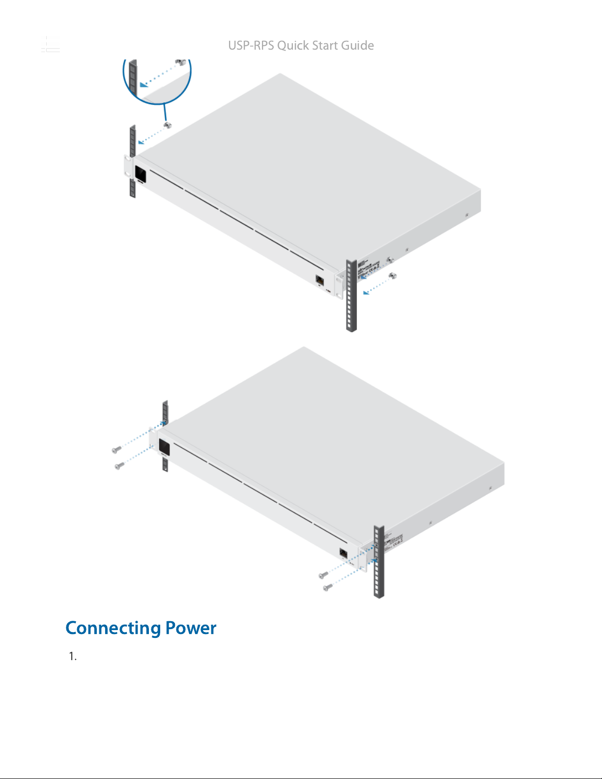
Connecting Power
1.
USP-RPS Quick Start Guide
Other manuals for USP-RPS
1
Other Ubiquiti Power Supply manuals

Ubiquiti
Ubiquiti EdgePower EP-54V-72W User manual

Ubiquiti
Ubiquiti UniFi SmartPower USP-RPS User manual

Ubiquiti
Ubiquiti EdgePower EP-24V-72W User manual

Ubiquiti
Ubiquiti EdgePower EP-54V-150W User manual

Ubiquiti
Ubiquiti EdgePower 54V User manual

Ubiquiti
Ubiquiti USP-RPS User manual

Ubiquiti
Ubiquiti EdgePower EP-54V-150W User manual
Popular Power Supply manuals by other brands

Videx
Videx 520MR Installation instruction

Poppstar
Poppstar 1008821 Instructions for use

TDK-Lambda
TDK-Lambda LZS-A1000-3 Installation, operation and maintenance manual

TDK-Lambda
TDK-Lambda 500A instruction manual

Calira
Calira EVS 17/07-DS/IU operating instructions

Monacor
Monacor PS-12CCD instruction manual


