manuals.online logo
Brands
  1. Home
  2. •
  3. Brands
  4. •
  5. MICRO-POWER
  6. •
  7. Power Supply
  8. •
  9. MICRO-POWER CDR 2.0 User manual

MICRO-POWER CDR 2.0 User manual

MICROPOWER - User guide
Baery isolator
CDR 2.0
INTENDED USE
The baery isolator CDR 2.0 is intended for charging current
distribuon between dual baeries/baery packs but can also
be used as an automac cut-o relay.
CDR 2.0 is suitable in automove and marine applicaons.
FEATURES
• Microprocessor controlled funcon
• Low voltage drops
• On/O status indicaon via external LED
• Waterproof and shock resistant
• Plasc housing
• Compact and easy to install
• On/O funcon
• Selectable between Unidireconal/Bidireconal
• Overvoltage switch-o
• All voltage levels (on, o, overvoltage) programmable during
producon
OPERATION
OPERATION STATUS
LED indicaon CDR output Descripon
O Inacve Voltage below switch-on
level or contact no 3
connected to ground.
Steady Acve Voltage within switch-on
levels or contact no 4
connected to ground.
Flashing × 3 Inacve Voltage out of range
Flashing 0.5 Hz Acve/
Inacve
0.5 Hz
Voltage > 29.05 V
Flashing × 4,
o 1 s, on 2 s
Inacve Overvoltage protecon
Voltage > 29.17 V
MECHANICAL INSTALLATION AND DIMENSIONS
• When a baery is connected and the voltage level is above level
a and less than level b, the CDR switch on and lets the voltage
through the terminals.
• If the voltage rises above level b, the CDR switch o to protect
equipment or auxiliary baery.
• When the voltage then drops below level c, the CDR switch on
again.
• If the voltage drops below level d, the CDR switch o.
12V system 24V system
SAFETY FIRST
WARNING, risk of electric shock.
High output voltage. Do not touch uninsulated baery
terminals, connectors or other live electrical parts.
Disconnect the baery before maintenance, servicing or
dismantling.
Do not operate the unit if there is any evidence of damage.
Only qualied personnel should install, use or service this product.
Read and understand this instrucon, the baery
instrucon provided by your baery manufacture, and
your employer’s safety pracce, before using, installing,
or servicing the product.
Operaon status can be indicated by connecng a LED to the
baery isolator.
• Install the baery isolator close to the baeries and use
appropriate cables to avoid unnecessary voltage drop.
• Posion the baery isolator so that the air supply is not
obstructed.
• The baery isolator
should always be
securely fastened.
• Protect supply cables
with suitable fuse/fuses.
• Max torque = 18 Nm for
terminal T-1 and T-2.
• Max torque = 10 Nm for
mounng screws.
• Use the insulang caps
supplied.
PRODUCT AND SUPPORT INFORMATION
For more informaon, visit Micropower Support Center:
Micropower Sweden AB
Idavägen 1, SE-352 46 Växjö, Sweden
Phone: +46 (0)470-727400
e-mail: support@micropower.se
www.micropower-group.com
ELECTRICAL INSTALLATION
1. Connect the posive terminal of the starter baery to
screw terminal T-1 (input).
2. Connect the posive terminal of the auxiliary baery to
screw terminal T-2 (output).
3. Connect an external LED between contact 1 and GND
(max 5 mA)
4. Connect contact 5 to ground (GND).
5. Connect the negave terminal of the starter baery
and the negave terminal of the auxiliary baery to
common ground.
Various oponal funcons can be installed via the contact
terminals 1-4.
CONNECTIONS OVERVIEW
T-1 Screw terminal 1, input
T-2 Screw terminal 2, output
1 LED, for connecng a LED
2 Bi/Uni, for changing the charging current distribuon
3 O, for the switch-o funcon
4 On, for the bypass funcon
5 GND
POSITIVE BATTERY CABLE CONNECTION,
UNIDIRECTIONAL
POSITIVE BATTERY CABLE CONNECTION,
BIDIRECTIONAL
Model CDR 12/24 V
Input voltage Universal 12 V or 24 V
Current limit 200 A I 100 A
Typical switch-on voltage 13.5 V I 27.4 V
Typical switch-o voltage 12.8 V I 25.6 V
Quiescent current, o < 1 mA
Quiescent current, on < 25 mA
Operang temperature –40 - +60 °C (−40 - +140 °F)
Ingress protecon (IP class) IP67
Weight 700 g
Contact terminals 6.3 mm Flat Pin connectors
TECHNICAL DATA
Doc: A03390 rev01
Print PN: 6540123
The CDR opens for charging current only in one direcon,
T-1 to T-2.
The CDR opens for charging current in either direcon,
T-1 to T-2 or T-2 to T-1.

Other MICRO-POWER Power Supply manuals

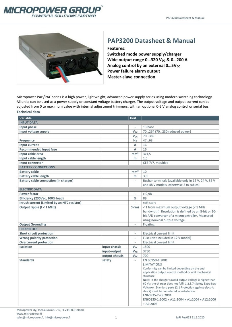
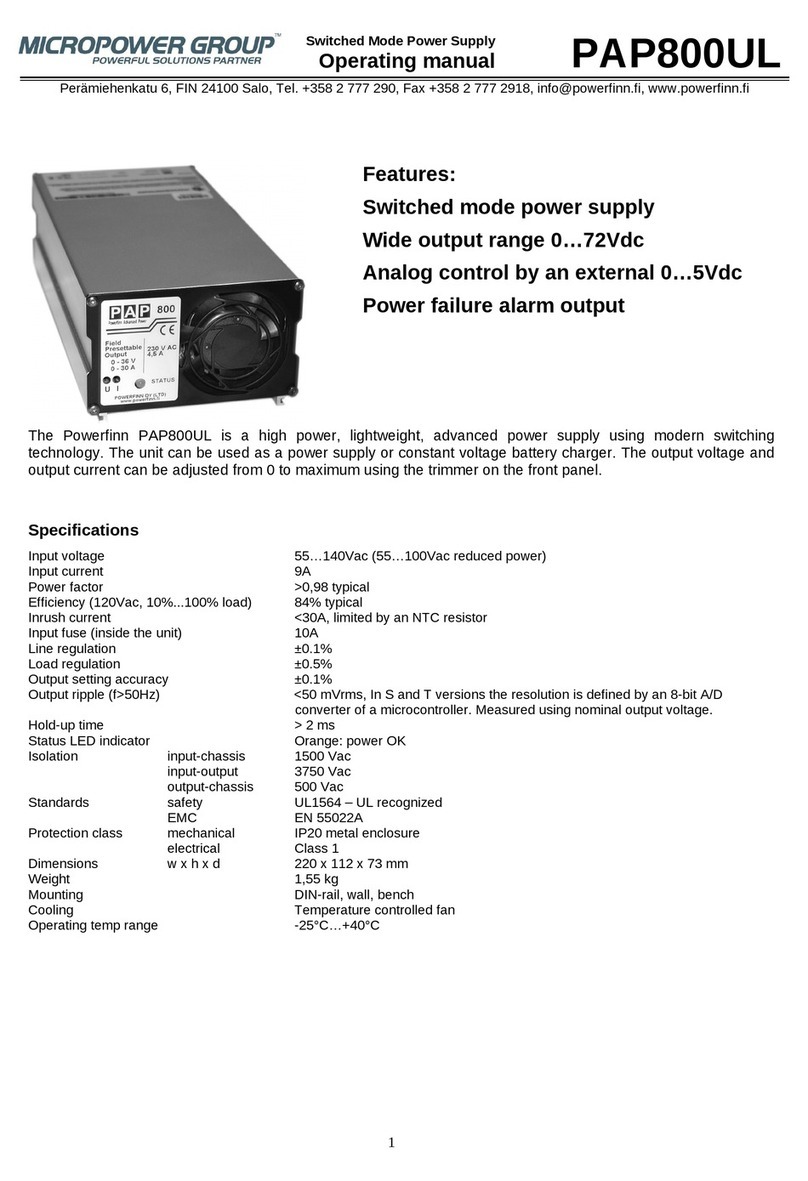
MICRO-POWER PAP800UL User manual

MICRO-POWER

MICRO-POWER PAP800UL User manual

MICRO-POWER PAP3200 User manual

MICRO-POWER

MICRO-POWER PAP3200 User manual

Popular Power Supply manuals by other brands

Pulsar ROUPS12VR quick start guide

Pulsar

Pulsar ROUPS12VR quick start guide

Huawei TP48200A-HX09A2 user manual

Huawei

Huawei TP48200A-HX09A2 user manual

H3C PS-2202-11L manual

H3C

H3C PS-2202-11L manual

Extech Instruments 382280 user guide

Extech Instruments

Extech Instruments 382280 user guide

JVA Wi-Fi Anywhere PTE2700 quick start guide

JVA

JVA Wi-Fi Anywhere PTE2700 quick start guide

Analytic Systems PWS120 Installation & operation manual

Analytic Systems

Analytic Systems PWS120 Installation & operation manual

Njoy Garun Series user manual

Njoy

Njoy Garun Series user manual

Allen-Bradley FLEX Ex 1797-PS2E2 installation instructions

Allen-Bradley

Allen-Bradley FLEX Ex 1797-PS2E2 installation instructions

Rockwell Automation Allen-Bradley 1606-XLE120EC installation instructions

Rockwell Automation

Rockwell Automation Allen-Bradley 1606-XLE120EC installation instructions

Ametek Sorensen DCS-E Series Operation manual

Ametek

Ametek Sorensen DCS-E Series Operation manual

FuG Elektronik MCA Series operating instructions

FuG Elektronik

FuG Elektronik MCA Series operating instructions

PEC Miniverter manual

PEC

PEC Miniverter manual

TYVA PowerCase E2 quick start guide

TYVA

TYVA PowerCase E2 quick start guide

Puls QT40 Series instruction manual

Puls

Puls QT40 Series instruction manual

Moore Industries DPS 240 manual

Moore Industries

Moore Industries DPS 240 manual

Festo 8049382 operating instructions

Festo

Festo 8049382 operating instructions

Diamond Antenna GZV4000 manual

Diamond Antenna

Diamond Antenna GZV4000 manual

StarTech.com ATXPOWER250 Instruction guide

StarTech.com

StarTech.com ATXPOWER250 Instruction guide

manuals.online logo
manuals.online logoBrands
  • About & Mission
  • Contact us
  • Privacy Policy
  • Terms and Conditions

Copyright 2025 Manuals.Online. All Rights Reserved.