micro-trak SafeGuard ISOmod User guide

Proudly built in
the U.S.A. by:
BL
OCKAGE
MONI
TOR

2
ISOmod™
SafeGuard™
SafeGuard™ ISOmod™ is an electronic blockage monitor that will help you achieve maximum
yields and operate more cost-effectively by providing the information you need to maintain
proper application rates of liquid chemicals and fertilizer. SafeGuard™ has been designed for
easy installation and operation.
SafeGuard™ - Simple, Powerful, Trusted Protection.
If you do encounter a problem that cannot be corrected by reviewing this manual, consult your
dealer or distributor, or contact Micro-Trak® for assistance.
Toll Free in U.S. or Canada: (800) 328-9613 or (507) 257-3600
Fax: 507-257-3001
Overview____________________________________________3
System Layout _______________________________________4
Sensor Conguration & Numbering ______________________5
ISOmod Installation ___________________________________6
Sensor Installation & Location ___________________________7
Implement Switch ____________________________________9
ISOBUS Connection __________________________________10
Operation __________________________________________10
On Screen Display ___________________________________11
On Screen Navigation ________________________________12
Home Screen _______________________________________13
About Screen _______________________________________13
Conguration Screen _________________________________14
Channel Setup ______________________________________16
Sensor Enable/Disable Screen __________________________16
Diagnostic Screen____________________________________17
Message Help Screen _________________________________17
Troubleshooting_____________________________________18
Sensor Measurements ________________________________19
Sensor Parts ________________________________________20
Optional Fittings_____________________________________21
Parts List ___________________________________________22
Warranty ___________________________________________25
Contents
Liquid Blockage Monitor for ISOBUS

3
System
The SafeGuard™ ISOmod uses an existing virtual terminal
(VT) in the cab to display liquid blockage information
and control settings. On-screen messages and simple
icon buttons on the virtual terminal access all monitoring
functions. View real-time status of individual and total
sensors arranged into dual networks and independent left
and right sensor banks. Data communication is based on
ISOBUS - ISO 11783 standards.
ISOmod™ Interface
This is the information processing unit of the SafeGuard™
ISOmod™ system - continuously scanning rows for
blockages and displaying information on the Virtual
Terminal screen. It provides the physical interface
between the liquid blockage sensors and the Virtual
Terminal. The wiring harness of the ISOmod connects to
the sensors and an available ISOBUS connection.
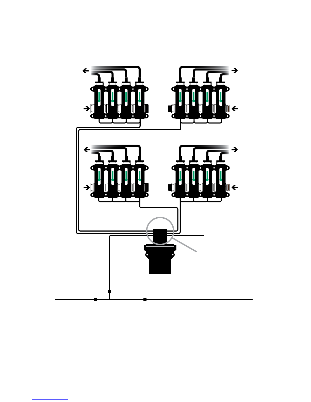
Sensor & Cartridges
The sensor assembly is a liquid flow chamber surrounded
by a blockage detection shroud. Its physical character-
istics are similar to visual flow monitor devices. The flow
openings accommodate plug (male) and cap (female)
fittings. (See page 21) The sensors may be mated with
other sensor assemblies or used individually. The chamber
contains a detection cartridge which rises with flow. A
fumigant-ready version of the sensor is also available.
Cartridges are available in a variety of weights to
accommodate a wide variety of liquid densities, and also
to provide partial blockage monitoring.
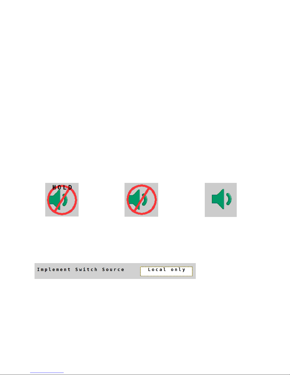
Implement Switch (optional)
The ISOmod wiring harness also has a Run/Hold con-
nection for an optional Implement Switch. This circuit
silences the audible alarm and also enables the review
of recorded screen information. (See page 11)
Micro-Trak makes an Implement Switch (P/N 18541)
with an integral magnetic mount designed to easily
connect to the ISOmod wiring harness.
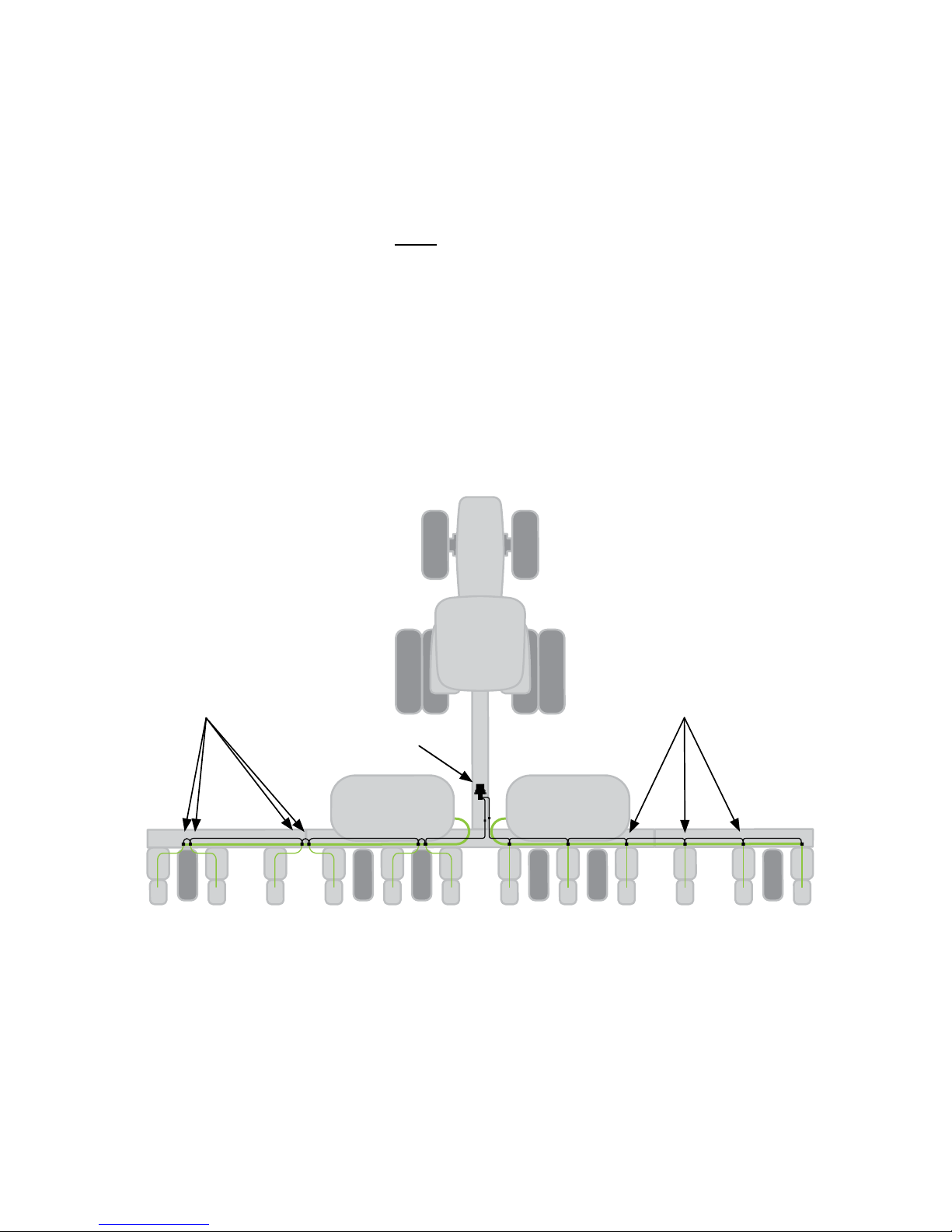
Overview
Sensor
Implement Switch
ISOmod™
Interface

4
Network 1
Network 2
L R
L R
ISOBUS
SafeGuard
ISOmod™
To Optional
Implement Switch
Micro-Trak Tap Cables
M/P 150 (Generic) - P/N 18894
Ampseal 16 (John Deere™) - P/N 18895
Delphi MP630 (Great Plains/Dickey-John™) - P/N 18896
Delphi GT280 (Case™) - P/N 18897
Deutsch™ DTM (in-cab) Kit - P/N 18944 (includes power cable)
Deutsch™ DT (in-cab) Kit - P/N 18945 (includes power cable)
Deutsch™ DT (in-cab) Kit - P/N 18950 (includes power adapter)
Micro-Trak IBIC Cable (for direct connection)
P/N 18921
Wiring Harness
P/N 19690
System Layout
This diagram shows an example of a typical layout. Your installation layout and
plumbing will vary depending on your system requirements. Arrows indicate flow.
(Note: Sensors do not need to be arranged symmetrically.)

5
Sensor Configuration & Numbering
The SafeGuard ISOmod system has 2 separate networks - labeled Net 1 & 2 on the
harness; each has a separate left and right side. Dual networks simplify monitoring
when applying 2 different products at the same time. On-screen configuration infor-
mation references any network and side (L/R) that is connected at start-up. Network
names can be edited from the Configuration Screen once the system is running on the VT.
Choose a location for the ISOmod enclosure near the center of the implement to
minimize the need for additional extension cables.
Note: From the ISOmod harness, Network Left connections have “Shroud” connectors
and Network Right connections have “Tower” connectors.
1 2 3
Network 1
LEFT
456
Network 1
RIGHT
1. Sensor leads face forward.
2. Left side of implement is connected to
“Left” connection on ISOmod harness (and
corresponding on right side).
3. Sensors are daisy chained but leads do
not cross.
4. Sensors numbered from LEFT to RIGHT -
low to high.
654
Network 1
LEFT
321
Network 1
RIGHT
1. Sensor leads face forward.
2. Left side of implement is connected to
“Right” connection on ISOmod harness (and
corresponding on right side).
3. Sensors are daisy chained and leads do
cross.
4. Sensors numbered from RIGHT to LEFT -
low to high.
Network 1
LEFT
654321
Network 1
RIGHT
1. Sensor leads face rear.
2. Left side of implement is connected to
“Right” connection on ISOmod harness (and
corresponding on right side).
3. Sensors are daisy chained but leads do
not cross.
4. Sensors numbered from RIGHT to LEFT -
low to high.
Network 1
LEFT
Network 1
RIGHT
1. Sensor leads face rear.
2. Left side of implement is connected to
“Left” connection on ISOmod harness (and
corresponding on right side).
3. Sensors are daisy chained and leads do
cross.
4. Sensors numbered from LEFT to RIGHT-
low to high.
61 2 3 4 5
1. 2.
3. 4.
1 2 3 4 5 6
6 5 4 321
6 5 4 321
Numbering Schemes

6
ISOmod Installation
1. Place the ISOmod™ enclosure in selected location, mark holes, drill, and secure
with 1/4” fasteners (not included). Mounting holes are 4” apart on center. (See
below)
2. Connect ISOmod™ wiring harness to sensors. Sensors are numbered starting
with farthest Left as #1 and continuing sequentially to the Right. The open
connectors on the last sensors on all network branches must have a termination
cap (included).
4 IN.
[101.6 mm]
ø5/16 IN.
[8 mm]

7
Sensor Installation & Location
Paired
Sensors are paired between rows.
1. Mount the sensors vertically with the outlet at the top. See sensor measurements
on page 19 for hole spacing. Sensors must be mounted plumb for correct
operation.
2. Sensor leads are daisy-chained together directly or with the use of extension
cables.
3. The last sensor in each grouping will have an unused connector. Termination caps
shipped with the ISOmod kit must be installed on any unused connector.
Sensors Over the RowSensors Paired
Over the Row
Sensors are placed at each row. Cabling connects to an end sensor and sensors are
daisy-chained together. Typically, sensors are plumbed together using fittings with
integral hosebarbs. (Available in 3/4” or 1” size.)
ISOmod™

8
Manifold style installation
Sensors are joined together using u-clips, like standard visual ball monitors. The
sensor with 3” leads would be used to minimize excess cabling between sensors.
Liquid can be fed to sensor groups via cap and plug fittings, or a Tee fitting designed
to link two sensors with a flow inlet.
SafeGuard™ Sensors
ISOmod™
Manifold style installation

9
Implement Switch
The implement switch mutes the audible alarm - preventing unwanted alarms and
pop-ups on the VT when the implement is not in use. It connects directly to the
ISOmod wiring harness. SafeGuard also responds to Implement Switch signals
available on the ISObus network.
Installation:
1. Remove the supplied jumper from the wiring harness connector labeled Run/
Hold.
2. Connect the implement switch connector labeled SafeGuard Run/Hold to the
wiring harness connector labeled Run/Hold.
The implement switch has a magnetic base which allows it to be easily positioned
on the implement. Simply mount the implement switch near a moving part of an
operating mechanism on your implement (additional extension cables may be
needed).
The switch is wired “Normally Open” and is connected between pins A & C. When the
switch is closed (pressure on tip) the audible alarm is on. When the switch is open
(no pressure on tip) the audible alarm is muted and HOLD is displayed. The display
continues to show blockage and error indications when HOLD is displayed.
Remember: +12 VDC on pin A = Audible alarm ON
Implement Switch Source:
Selects source for implement switch signal.
Local Only - SafeGuard will react to an Implement Switch that is connected
directly to the wiring harness or available signals on the ISObus network.
12345 (example) - SafeGuard will only react to Implement Switch information
originating from a Micro-Trak ISOmod. If that signal is available, a
button with the last 5 digits of the ISOmod serial number will be visible.
(Configuration Page)
Receiving Implement
Switch “HOLD”
Audible Alarm Off Audible Alarm On
Implement Switch / Alarm Volume Display Icons

10
Operation
When the system is turned on, SafeGuard ISOmod searches for sensors installed on
the data line. If the number of sensors it finds is different than the last power-up, it will
notify the user with an on-screen message.
Example:
Always confirm the number of detected sensors is correct when the system is pow-
ered-up. If the number of sensors detected differs from the actual number of sensors
installed, troubleshoot the missing sensors. (See page 18)
The system continuously monitors the sensors for blockage. When a blockage is
detected, SafeGuard immediately alerts the operator by flashing the warning triangle
icon, sounding an audible alarm, and displaying the number of the blocked sensor.
This alert will remain until the blockage is acknowledged. With Hold activated by an
implement switch, the display will still show blockages, but audible alarm is muted
and pop-up screen activity is disabled.
NOTE: The open connectors on the last sensors on all network branches must have a
termination cap (included).
ISOBUS Connection
The SafeGuard ISOmod joins to existing ISOBUS compatible connectors to display
liquid blockage information on a Virtual Terminal.
Micro-Trak manufactures “Tap Cables” which allow the SafeGuard ISOmod to connect
without interrupting other devices already in use, and an IBIC breakaway cable to
allow the SafeGuard ISOmod to directly connect to an ISOBUS network.
Micro-Trak Tap Cables
• M/P 150 (Generic) - P/N 18894
• Ampseal 16 (John Deere™) - P/N 18895
• Delphi MP630 (Great Plains™/Dickey-John™) - P/N 18896
• Delphi GT280 (Case™) - P/N 18897
• Deutsch DTM (in-cab) Kit (includes power cable) - P/N 18944
• Deutsch DT (in-cab) Kit (includes power cable) - P/N 18945
• Deutsch DT (in-cab) Kit (includes power adapter) - P/N 18950
Micro-Trak IBIC Cable - P/N 18921

11
On Screen Display
The SafeGuard ISOmod is designed to integrate into serial networks that use ISOBUS
standards - ISO 11783. The appearance of the on-screen display will vary depending
on the brand of Virtual Terminal that is used.
The system is also designed to run along side, and in the background, with other
programs on the VT. When a blockage situation happens, the SafeGuard ISOmod
screen will pop-up to the front to allow the user to assess the situation.
NOTE: Blockage monitoring is only active from the Home Screen.
Recording Blockage Information
Problem blockages can be recorded for later review by pressing the “Record Current
Screen” icon during the blockage. The recorded information can later be recalled and
played back when the system is in Hold. (If an Implement Switch is not used, this will
require removing the jumper from the connector on the Run/Hold line.)
Reviewing Recorded Blockage Information
To review information:
1. Place system in HOLD.
2. Press “Play” icon . The top of screen will display “Playback” and recorded
blockage information will be shown.
3. If multiple blockages are recorded, press the arrow icons to navigate
or press “Play” to scroll through automatically. Scrolling can be stopped by
pressing “Pause” .

12
HOME
ABOUT
CH. 1 ON/OFF CH. 2 ON/OFF
HELP
DISCONNECT
DIAGNOSTIC
CH. 1 SETUP
CH. 2 SETUP
ENABLE/DISABLE
2
ENABLE/DISABLE
1
SECTION SETUP
SECTION SETUP
CONFIGURATION
(Return to Home Screen)
1 2
On Screen Navigation
The solid lines show navigation paths forward and back from screen to screen, while
the dashed lines indicate paths leading directly back to the HOME screen.
Note: Section Setup is only available when SafeGuard is configured for Section
Control and a Micro-Trak Dual ISOmod Rate Controller is also connected to the ISOBUS
network.

13
Home Screen
Home Screen for system. System is actively monitoring for blockages.
About Screen
Displays system information.
System is NOT actively monitoring for blockages.
To About Screen
To Configuration Screen
Volume Decrease &
Run/Hold Status
Record Current Screen
Refresh System
Channel 1 On/Off
Channel 2 On/Off
Volume Increase
To Message Help Screen
Return to Home Screen
Totals and locations
of connected
SafeGuard Blockage
sensors
Network #1 Name
Network #2 Name
To Message Help Screen

14
Configuration Screen
Configure System. System is NOT actively monitoring for blockages.
To Home Screen
To Diagnostic Screen
To Channel 1 Setup
To Channel 2 Setup
Implement Switch Source
Section Control Source
Section Control
If a Micro-Trak Dual ISOmod is also connected to the ISOBUS network, SafeGuard
sensors can be grouped and assigned to respond to Section Control messages. This
means that as sections are individually controlled on the Dual ISOmod, SafeGuard will
selectively turn off sensors to prevent false alarm readings.
Section Control Setup:
1. Choose MTSI Control as Section Control Source.
2. Choose the channel for setup.
3. Choose the Section Control Source that matches the last 5 digits of the serial
number of the connected Dual ISOmod. Select the intended Channel at right to
associate sections to.
4. Press the Sensor Assign icon at right. (Channel 1 shown.)

15
5. Assign sensors to available sections. Sensors are assigned in ascending numerical
order - refer to page 5 for numbering schemes. In the example shown, Sensor
1 is assigned to Section 1, Sensor 2 is assigned to Section 2, Sensors 3 & 4 are
assigned to Section 3, and so on.
6. Press Home to complete Section Control setup or return to Channel setup for
further editing.
Section Control cont.

16
Channel Setup Screen
(Channel 1 shown.)
Channel Name
To Home Screen
To Configuration Screen
To Channel 2 Setup
To Channel 1 Sensor
Enable/Disable
Section Control
See Page 14
Total Sections
See Page 14
Sensor Enable/Disable Screen
Sensor Enable/Disable - Press icon to toggle.
System is NOT actively monitoring for blockages.
• Green icon indicates enabled
• Red icon indicates disabled
To Home Screen
To Channel 1 Setup

17
Diagnostic Screen
Message Help Screen
To Home Screen
To Configuration Screen
Disconnect
Message Help
information
To Home Screen
To About Screen
Note: Information shown here is an example only. Your SafeGuard ISOmod will have
specific identity information.
Disconnect:
This softkey will disconnect the SafeGuard from the ISObus, effectively turning
it off.

18
Sensors Not Detected
Several sensors in a row missing - Check connection between last good sensor
and first bad sensor. Bypass first bad sensor in string with extension cable or
adjacent sensor leads to troubleshoot.
Single sensors not detected - Isolate or verify bad sensor by bypassing suspect
sensor with extension cable or sensor leads. Press refresh to re-scan for
sensors.
Implement Switch Not Working (P/N 18541)
HOLD indication on display won’t go out
Using a jumper wire, short pin A to pin C on three-pin implement switch
connector or re-install factory jumper. If the HOLD indicator goes away, trouble-
shoot the implement switch.
Sensor not detecting blockage or showing blockage when not present
Doesn’t read BLOCKED
If the cartridge is at the bottom of the sensor assembly and the sensor does
not indicate BLOCKED, verify cartridge is in sensor tube with tail on top/ball on
bottom. If this is correct, replace sensor.
Doesn’t read GOOD
Remove cartridge from sensor chamber. Sensor should read GOOD. If it doesn’t
read GOOD with cartridge removed, replace sensor.
Troubleshooting

19
Sensor Measurements
5/16 IN.
[8.00 mm]
4 21/32 IN.
[118.23 mm]
2-11/32 IN.
[59.50 mm]
2-11/32 IN.
[59.50 mm]
2-11/32 IN.
[59.50 mm] 2-5/8 IN.
[66.675 mm]
5/16 IN.
[8.00 mm]
4 21/32 IN.
[118.23 mm]
Sensor Measurements with Tee fitting

20
Sensor Parts
Cartridge Retainer
Tower
Connector Shroud
Connector
P/N 18514
Green Cartridge
P/N 18511
U-Clip, stainless steel
P/N 18510
FKM (Viton® type)
O-Ring
P/N 18521
SafeGuard Sensor Kit:
Includes sensor body, green cartridge,
cartridge retainer, O-ring, and 2 U-clips.
P/N 01994 - Standard Liquid w/3”leads
P/N 01995 - Standard Liquid w/20”leads
P/N 01996 - Fumigant Compatible w/3” leads
P/N 01997 - Fumigant Compatible w/20” leads
Important Note:
Eective Jan.1 2017,
SafeGuard™ sensor plugs
changed from gray JWPF to
black Amphenol. Be certain
to check vintage prior to
ordering repl. parts.
Pre-2017 2017-after
G R AY BLACK
Table of contents
Other micro-trak Measuring Instrument manuals