micro-trak SPEED-O-METER 13347 Administrator Guide

Installation/Operator’s Manual
Add digitally accurate measurement
to any vehicle with a 12V power
supply: ATV’s, tractors, industrial
equipment, trucks, etc.
SPEED-O-METER
TM
LR
Accurate Digital Measurement

SPEED-O-METER
TM
LR
Accurate Digital Measurement
INSTALLATION/OPERATOR’S MANUAL
The SPEEDOMETER is a precision-engineered electronic monitor that directly calculates speed, and distance, and with an
optional sensor kit, will provide engine or shaft RPM. In any operation — from chemical application to turf care to harvest —
the SPEEDOMETER provides valuable information that can help reduce your operating cost and increase overall efficiency.
This manual is written for the SPEEDOMETER Model SOM-97-LR. Please read the manual carefully and follow the instructions
as they apply to your usage. The installation, calibration and operational procedures described will produce maximum
accuracy and ensure years of trouble-free performance.
If you do encounter a problem that cannot be corrected by reviewing this manual, consult your dealer or call our technical
personnel for assistance.
Toll Free in U.S. or Canada: (800) 328-9613 or (507) 257-3600
E-mail: [email protected]
Web: www.micro-trak.com
Mfg. in U.S.A.
1305 Stadium Road
Mankato, MN 56001-5355
© Copyright 2007
Micro-Trak Systems, Inc.
Printed in the U.S.A.
2

3
Micro-Trak®Warranty
Micro-Trak (herein “Seller”) warrants to the original purchaser (herein “Buyer”) that, if any product or part of the product (herein “part”)
proves to be defective in material or workmanship, upon inspection and examination by Seller, within one (1) year from the original date-
of-purchase, and is returned to Seller with dated proof-of-purchase, transportation prepaid, within thirty (30) days after such defect is
discovered, Seller will, at their option and sole discretion, either repair or replace said part, except that the warranty for expendable parts,
including but not limited to, light bulbs and batteries shall be thirty (30) days from the original date-of-purchase. Said warranty is valid only
when the part has been installed, operated and maintained in strict accordance with the procedures outlined in the manual. Any damage
or failure to said part resulting from abuse, misuse, neglect, accidental or improper installation or maintenance, unauthorized modification,
use with other products or attributable to acts of God, as determined solely by the Seller, will invalidate the warranty. Said part will not be
considered defective if it substantially fulfills the performance specification. Buyer shall be responsible for all maintenance services, if any,
all in strict accordance with the procedures outlined in the manual. The warranty does not include labor, installation, replacement parts or
repairs, delivery of replacement parts or repairs or time and travel. Said warranty is nontransferable.
The foregoing warranty is exclusive and in lieu of all other warranties of merchantability, fitness for purpose and of any other type, whether
express or implied. The Seller’s liability, whether in contract, in tort, under any warranty, in negligence or otherwise, shall not exceed the
return of the amount of the purchase price paid by the Buyer, and under no circumstance shall the Seller be liable for special, indirect or
consequential damages. Seller neither assumes nor authorizes anyone to assume for it any other obligation or liability in connection with
said part. No action, regardless of form, arising out of the transactions under this agreement may be brought by the Buyer more than one (1)
year after the cause of action has occurred.
Seller agrees to extend the term of the foregoing warranty period should the Buyer return completed warranty registration information,
with dated proof-of-purchase, to the Seller within one (1) year from the original date-of-purchase. All conditions and limitations of said
foregoing warranty, except the term of said foregoing warranty, shall apply. Said term shall be extended to a total of three (3) years from the
original date-of-purchase on display consoles and network communication modules, as defined by Seller, and said term shall be extended
to a total of two (2) years from the original date-of-purchase on all other parts, except that the warranty for expendable parts, including but
not limited to, light bulbs and batteries shall be thirty (30) days from the original date-of-purchase and except that the warranty for parts
manufactured by someone other than the Seller, including but not limited to, shutoff and control valves, DGPS receivers, memory cards and
drives, mapping software, flowmeters and pressure sensors shall be one (1) year from the original date-of-purchase.
Buyer accepts these terms and warranty limitations unless the product is returned to Seller, via proper distribution channels and approved
return authorization, with dated proof-of-purchase, transportation prepaid, within fifteen (15) days from the date-of-purchase for refund of
the purchase price.
Units under warranty should be sent prepaid, with dated proof-of-purchase, within thirty (30) days of discovering defect, to the address
below:
Mail and UPS:
Micro-Trak Systems, Inc.
Attn.: Service Department
1305 Stadium Road
Mankato, MN 56001-5355
Extended Warranty Option
It’s simple! Just complete the enclosed registration card(s) for this product
and mail it in and we’ll extend your warranty for up to three years*, at no additional charge.
MAIL IN YOUR REGISTRATION CARD TODAY!
Registration card information is for internal use only.
* Some limitations apply. See warranty statement for details.
At Micro-Trak Systems, we believe a product that delivers quality and performance at a low cost is what is needed to help today’s operator and the operator of
the future compete in the world market.
It is our goal to provide operators with a line of electronic equipment that will help build and maintain an efficient and profitable operation that can be passed
on to future generations.
We thank you for your purchase and hope that we can be of service to you in the future.
Micro-Trak Systems, Inc.

4
Table of Contents
Warranty................................................................................................................................................................................................3
Table of Contents ................................................................................................................................................................................4
Installation...................................................................................................................................................................................... 5-12
Component Parts and Assembly Hardware............................................................................................................................................... 5
Required Tools ...................................................................................................................................................................................................... 6
Mounting the Display Console ....................................................................................................................................................................... 6
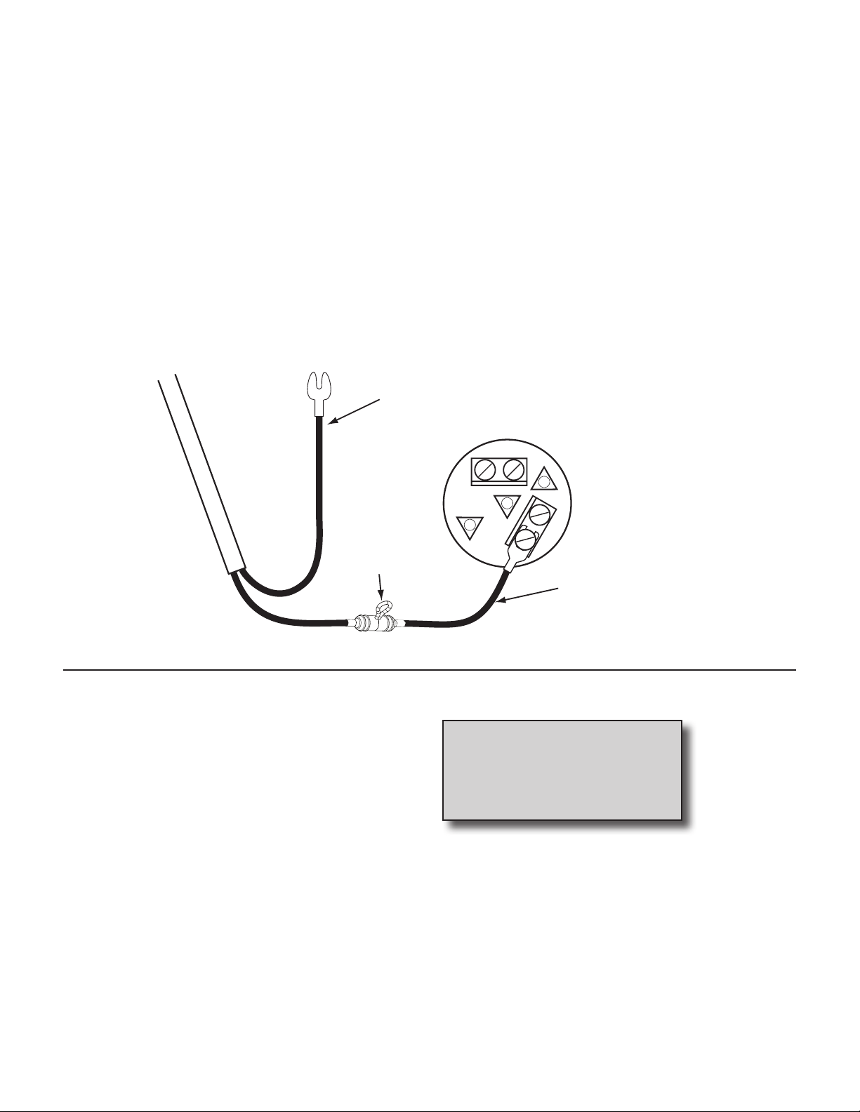
Electrical Installation........................................................................................................................................................................................... 7
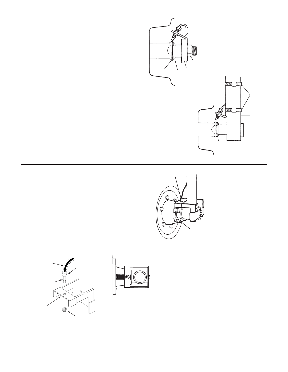
Speed Sensor Installation............................................................................................................................................................................7-11
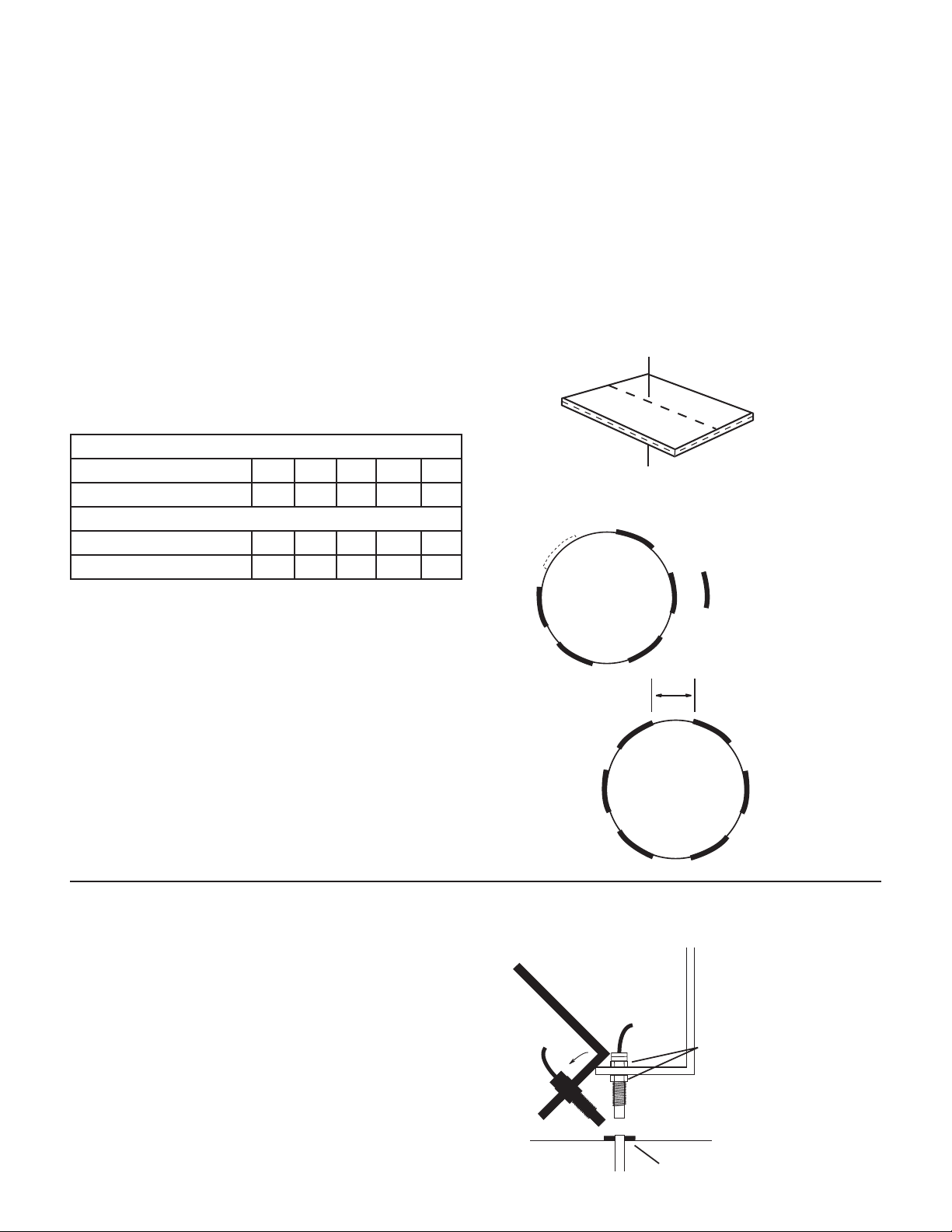
Magnets........................................................................................................................................................................................................... 8
Attaching Magnets to Hub....................................................................................................................................................................... 8
ATV Wheels .................................................................................................................................................................................................... 9
Front Tractor Wheels.................................................................................................................................................................................. 9
Implement Wheels ....................................................................................................................................................................................10
Optional Drive Shaft Mount...................................................................................................................................................................10
Optional Gas Engine RPM Sensor Installation.........................................................................................................................................11
Optional Tach/Shaft Sensor Installation....................................................................................................................................................11
Speed Sensor Options......................................................................................................................................................................................12
Care and Maintenance .....................................................................................................................................................................12
Console Functions.............................................................................................................................................................................13
Calibration ....................................................................................................................................................................................14-15
Field Calibration - Speed and Distance ...................................................................................................................................................14
Optional Distance Calibration .......................................................................................................................................................................14
RPM Calibration ..................................................................................................................................................................................................15
Operation......................................................................................................................................................................................15-16
Measuring Speed ...............................................................................................................................................................................................15
Measuring Distance...........................................................................................................................................................................................15
Measuring Hours ................................................................................................................................................................................................15
Measuring RPM...................................................................................................................................................................................................15
Resetting System Counters ............................................................................................................................................................................15
Optional Features .............................................................................................................................................................................................16
Over-Speed Alarm Instructions ............................................................................................................................................................16
Troubleshooting..........................................................................................................................................................................17-18
Console Appears Dead.....................................................................................................................................................................................17
Speed is Always Zero or Erratic.....................................................................................................................................................................17
Console is Erratic in Operation......................................................................................................................................................................17
Checking Individual Components ...............................................................................................................................................................18
Console..........................................................................................................................................................................................................18
Harness ..........................................................................................................................................................................................................18
Power .............................................................................................................................................................................................................18
Accessory Power ........................................................................................................................................................................................18
Magnetic Hall-effect Sensor...................................................................................................................................................................18
Console Input..............................................................................................................................................................................................18
Speed Input .................................................................................................................................................................................................18
RPM/Tach Input..........................................................................................................................................................................................18
Appendices...................................................................................................................................................................................19-22
Appendix A: Radar “Y” Cables .....................................................................................................................................................................20
Appendix B: Conversion Tables..................................................................................................................................................................21
Appendix C: Parts List.....................................................................................................................................................................................22

(2)
(2)
(2)
(2)
(2)
(2)
(2)
C B A
A B C D E
C B A
A B C
SPEED
(YELLOW TIE)
RPM
(RED TIE)
POWER
Component Parts and Assembly
Before beginning installation, check the carton contents for the following items:
Speed-O-Meter Console
P/N 13347
Installation/Operator’s Manual
Add digitally accurate measurement
to any vehicle with a 12V power
supply: ATV’s, tractors, industrial
equipment, trucks, etc.
SPEED-O-METER
TM
LR
Accurate Digital Measurement
Reference Manual
P/N 13243
Console Mount Kit
P/N 13181
10’ Power, Speed and RPM Harness
P/N 13368
Speed Sensor Kit
P/N 01531
Hall-effect Speed Sensor Cable
with Threaded Sensor
P/N 13096
Magnets (6)
P/N 12096 Hardware Bag
P/N 13251
15’ 3-Pin Extension Cable P/N
13207
Nylon Cable ties
P/N 12910 Speed Sensor
Mounting Bracket (1)
P/N 10013
5

CONSOLE END VIEW
Console easily adjusts for
side or dashboard mounting.
6
Tools Needed to Install Speed-O-Meter
• Screwdrivers and Nutdriver
• Electric Drill and Bits • Pliers
• Tape Measure
Installation
Required Tools
Installation of your SPEEDOMETER is basically a three-step
procedure. Each installation will vary somewhat, depending
on your type of equipment. Allowances for these differences
have been made through the design of flexible mounting
brackets and extra hardware.
Mounting the Display Console
Select a mounting location which seems most workable,
and best fits your needs. It should be convenient to reach
and highly visible to the operator. DO NOT INSTALL IN
A POSITION THAT OBSTRUCTS THE VIEW OF THE ROAD
OR WORK AREA. Whenever possible, avoid locations that
expose the console to direct sunlight, high temperature,
strong chemicals or rain.
Place the mounting bracket in the selected location, mark
holes, drill 1/4” (7mm) holes and mount bracket with bolts,
lockwashers and nuts provided. (Use self-tapping screws if
not practical to use bolts.) See Illustration 1.
Put rubber washers on carriage bolts and put the bolts
through the bracket holes from the inside out. Loosely
attach the mount knobs onto the bolts. Place console over
carriage bolt heads and tighten knobs to secure the console.
See Illustration 2.
Note: Some systems may use two “L” brackets in place of
the “U” bracket for console mounting.
Illustration 1
Drill ¼” (7mm)
holes for bolts,
or 3/16“ (5mm)
holes for self-
tapping screws.
Bolts
Lockwashers
and nuts
Rubber washer
Carriage bolts
Mount knob
Illustration 2

Black to Ground
Attach RED wire to
terminal or lead that is
“hot” with ignition on.
2-amp in-line fuse required (Not Provided) for unprotected circuits
FUSEHOLDER
Locate the Following Parts
• Speed Sensor Cable (Green Body)
• Mounting “L” Brackets
• Cable Ties
• Magnets
Installation (cont)
Electrical Installation
Illustration 3
The SPEEDOMETER must be connected to a 12-volt DC
electrical system. Using your test light, locate a terminal or
wire connected to your ignition switch which is “hot” when
the ignition is turned on and “dead” when the ignition is off.
Locate the power cable on the main wiring harness. Connect
the RED wire to the contact point you have located. Attach
the BLACK wire (ground) to a screw or bolt on the equipment
frame. See Illustration 3. Be sure there is a good metal-to-
metal contact. The terminal connectors have been supplied
for your convenience. You may wish to substitute other
types of connectors or make direct solder connection. In
routing cable to console, avoid areas where the cable may be
subjected to abrasion or excessive heat.
Locate the single BLUE wire supplied with the kit to make a
ground wire. Crimp a female spade terminal on one end and
a ring terminal on the other end. Attach the spade terminal
end of the BLUE wire to the mating spade terminal on the
back of the console. Attach the ring terminal end of the BLUE
wire to a screw or a bolt on the equipment frame. Be sure
there is good metal-to-metal contact.
Your SPEEDOMETER is equipped with an advanced
electronic memory which does not require a constant supply
of power to retain daily totals or calibration values. The
advantage with this type of memory is that it conserves
battery power and will not discharge the vehicle’s battery
when equipment is not is use.
NOTE: For negative ground systems ONLY.
7
Speed Sensor Installation
PLEASE NOTE: If you have purchased an Astro GPS Speed
Sensor or a Vansco Radar Speed Sensor, disregard the
following section on magnetic speed sensors and install
the speed sensor as described in the instructions included
with the unit. See Appendix for adapter cables to connect
to some radars.
Locations where the sensor may be installed:
1. Non-driven wheel on tractor, vehicle or implement. This
is less susceptible to error resulting from wheel slip.
2. Tractor, vehicle or planter drive shaft. This type of
mounting is recommended for trucks, four-wheel drive
tractors or other equipment that has poor or no access
to a non-driven wheel.

Please read the following information about magnet spacing
and polarity.
The number of magnets that must be used depends on
the size of your tire and where you mount the sensor. On
tractor or implement wheels the general rule of thumb is one
magnet for each wheel bolt (minimum of two, and always an
even number). For drive shafts or small wheels (ATV’s), two
magnets are usually adequate.
Some installations may require that more than two magnets
be installed. To determine the number of magnets required,
measure the distance traveled of one revolution of the
sensor equipped wheel in inches (centimeters).
See the following tables to find the minimum number of
magnets required (always an even number)
Attaching Magnets to Hub
The magnets are attached to a wheel hub or drive shaft and
the speed sensor is mounted directly over the magnet. When
the wheel or drive shaft begins turning, a speed impulse is
sent to the FlowTrak II console every time a magnet passes
by the tip of the speed sensor. For the speed sensor to
operate properly, the spacing between the magnets and
the tip of the sensor must always remain constant. Before
permanently mounting any parts, be sure that the location
you have selected will meet the requirements shown in
Illustration 6.
NOTE: Observe magnet polarities (see previous section).
Installation (cont)
Magnets
8
NOTE: Magnets may be attached mechanically or adhered
with epoxy or other high quality adhesive. When using
adhesive, thoroughly clean the area of dirt and oil.
The magnets provided by Micro-Trak are marked with a
punched dashed line on the SOUTH pole side of the magnet.
See Illustration 4.
Always use an even number of magnets, and always alternate
the polarities of the magnets as you go around the wheel
hub or drive shaft.
To install, mount the first magnet with the SOUTH pole side
(dashed line) facing toward the hub or shaft. Mount the
second magnet with the NORTH pole side facing toward the
hub or shaft. See Illustration 5.
For proper operation, the magnets must be evenly spaced
around the wheel or drive shaft. The magnets must be at
least 1” apart. See Illustration 5A.
English or Turf (inches)
Wheel Circumference 40 80 120 160 200
Number of Magnets 2 4 6 8 10
Metric (cm)
Wheel Circumference 100 200 300 400 500
Number of Magnets 2 4 6 8 10
S
N
North
North
North
South
South
South
1
2
43
5
6
Test magnet
should alternately
attract and repel.
1” M
inimum
Illustration 4
Illustration 5
Illustration 5A
45° max
Sensor
(Green body)
Magnet
3/8” nuts
Bracket must
be rigidly
mounted
Sensor assembly must not
be mounted more than
45° from perpendicular
¼” to ½” air gap
Illustration 6

Front Tractor Wheel
1. Magnets may also be secured with a cable tie and an
adhesive such as epoxy.
2. Mount the speed sensor bracket to a part of the wheel
assembly that does not change position to the hub when
the wheels are turned. If the “L” bracket provided cannot
be bent and mounted to properly position the sensor,
make a bracket similar to the one shown at right.
3. Install sensor, adjust to correct spacing (1/4” to 1/2 “
or 6 to 13 mm is recommended), and secure with 3/8”
locking nuts.
Illustration 7
Installation (cont)
ATV Wheels
9
Sensor Bracket
Axle
Nut
Swing Arm
Hub
Rim
Plastic
Cable
Tie
Magnet
Cut Bracket
to Clear Rim
Cut and Bend
Bracket as
Required Metal
Hose
Clamps
Fork
Tube
Axle
Hub
Rim
Magnet
Cable Tie
Speed Sensor
Tap thread for
bolts or weld
Hub
Top View
FABRICATED BRACKET
Sensor
3/8” nut
Optional section
of hose to
protect cable
3/8” nut
3/8” hole
for sensor
Refer to the following diagrams for specific mounting
instructions. Magnets may be attached mechanically as
shown or adhered with epoxy or other high quality adhesive.
When using adhesive, thoroughly clean the area of dirt
and oil. With either method of attachment, wrapping the
magnets with a layer of electrical tape is recommended to
provide additional protection from field debris.
Two mounting examples are illustrated.
1. Using one cable tie (ribbed side down) secure two
magnets to the wheel hub so they are exactly opposite
each other. Alternate the magnets’ polarities. See page 8
for proper procedure.
2. Cut and bend sensor mounting bracket as needed and
rigidly mount. See Illustration 7.
3. Insert sensor, adjust spacing and secure with 3/8” locking
nuts.
NOTE: Observe magnet polarities (see page 8).
CAUTION: Make sure valve stem cannot make contact with
cable, sensor or bracket.

Installation (cont)
Implement Wheels
Speed Sensor
and Bracket
¼” Bolts,
Lockwashers
and Nuts
Speed Sensor
Cable Tie
1. Secure magnets mechanically or with epoxy.
2. Rigidly mount sensor mounting bracket to the wheel
assembly. Cut or bend “L” bracket as required for proper
positioning of sensor.
3. Install sensor, adjust to correct spacing (1/4” to 1/2 “
or 6 to 13 mm is recommended), and secure with 3/8”
locking nuts. See Illustration at right.
10
Speed Sensor Mounting on Drive Shaft
Determine the best location for the magnets on drive shaft
according to which is the most practical spot to attach sensor
mounting bracket. This position should be no more than 12”
(.30 meters) behind the front U-joint. For best results, mount
“L” bracket to transmission and mount magnets on drive
shaft as close to transmission as possible. This will ensure
proper alignment if drive train shifts under heavy loading.
Two magnets are required for proper Hall-effect speed
sensor operation. Position them exactly opposite each other
(180 degrees apart). The polarity (north and south poles)
detected by the Hall-effect speed sensor must alternate as
the shaft is turned. The magnets provided by Micro-Trak are
marked with a punched dashed line on the SOUTH pole side
of the magnet.
• Attach magnets onto drive shaft, one NORTH pole side
out and the other SOUTH (dashed) pole side out, by
wrapping cable tie around shaft and magnets. Position
each magnet so that its longest dimension moves in
the direction of rotation. Pull cable tie tight and trim
off excess. An adjustable, non-magnetic (stainless steel)
band clamp may also be substituted.
• Attach sensor bracket to vehicle transmission. See
Illustration below. Use either the short or long end of
the bracket as a base.
• Turn one locking nut onto threaded sensor and insert
sensor into large hole selected on mounting bracket.
Turn on remaining locking nut. Set sensor to proper
distance from magnets (1/4” to 1/2”, or 6mm to 13mm).
When distance is set, tighten nuts to lock sensor in
place.
• Secure sensor cable to frame with cable ties. Place first
tie as close to sensor assembly as possible.
T
ransmission/ Transfer Case Drive Shaft
Magnets Positioned
180° Apart
¼” to ½”
(6mm to 13mm)
Spacing
Sensor Body
(Green)
Fasten Sensor Bracket with
Existing Transmission Bolts
or Rigidly Attach with Clamps.
Illustration 8

Installation (cont)
Optional Gas Engine RPM Sensor Installation
11
Illustration 9
The inductive sensor in this kit is ONLY for use on gas
engines. Secure the RPM sensor on any convenient spark
plug wire with electrical tape or plastic ties. The white mark
on the sensor must be positioned directly over the spark plug
wire. The spark plug wire and sensor must be as far away as
possible from all other plug wires. Route the sensor cable
away from heat and moving parts and secure them in place
with plastic ties. See Illustration 9. Connect to the RPM lead
on the main harness. See Illustration 13 on page 18.
RPM SENSOR
ELECTRICAL TAPE
OR CABLE TIES
SPARK PLUG WIRES
WHITE MARK
The optional tach/shaft RPM sensor can be mounted on the
drive shaft of cars, pick-ups, 4-wheel drive tractors, planters
or to the wheel hub or fork tube on ATV’s, cycles and other
vehicles.
Rigidly fasten the sensor mounting bracket in a suitable
location, or where the drive shaft has MINIMUM up/down
movement. It may also be attached under the axle nut or fork
tube using 1/4” bolts, self-tapping screws, hose clamps or
by welding it into place. CAUTION: Disconnect the console
from the battery before welding. Secure the cable with
plastic cable ties. A rubber or plastic hose over the sensor
cable will provide added protection against debris.
1. Two magnets are required for proper Hall-effect speed
sensor operation. Position them exactly opposite each
other (180 degrees apart). The polarity (north and south
poles) detected by the Hall-effect speed sensor must
alternate as the shaft is turned. Follow these steps
the make sure you attach the magnets correctly with
alternate polarities:
2. Stick the two magnets together. Put an “x” on the top
magnet. Remove the magnet and put and “x” on the
second magnet. When you attach the magnets to the
drive shaft, make sure one “x” is facing toward and one
“x” is facing away from the drive shaft. The magnets will
be correctly attached with alternate polarities.
Optional Tach/Shaft RPM Sensor Installation
3. Attach magnets onto drive shaft by wrapping cable
tie around shaft and magnets. Position each magnet
so that its longest dimension moves in the direction
of rotation. Pull cable tie tight and trim off excess. An
adjustable, nonmagnetic (stainless steel) band clamp
may also be substituted. If you are using a hose clamp,
position the adjusting screw between the magnets. The
hose clamp must be non-magnetic stainless steel. When
using adhesive, thoroughly clean the mounting area of
dirt and oil.
4. With either method of attachment, wrap electrical tape
over the magnets for added protection against field
debris.
5. Adjust the sensor so that the un-threaded tip extends
1/4” (10mm) beyond the locking nut with a 1/4” to 1/2”
(6mm to 12mm) air gap from the tip of the sensor to the
magnet. See Illustration 10. Be sure that the cable tie or
hose clamp adjusting screw will not hit the sensor when
it is rotated. The sensor may be angled up to 45º from
perpendicular, but it must be positioned directly over
the magnets.
Illustration 10
SELF-TAPPING
SCREWS OR BOLTS
SENSOR BRACKET ASSEMBLY
(GREEN BODY)
¼” (7mm)
MINIMUM EXTENSION ¼” to ½” (7 mm to 14 mm)
SPACING
MAGNETS POSITIONED
180° APART
DRIVE
SHAFT
MAGENT WITH LONG DIMENSION
IN DIRECTION OF ROTATION
DRIVE SHAFT
CABLE TIE (RIBBED SIDE
T
OWARDS MAGNET) OR
NON-MAGNETIC HOSE CLAMP

In addition to the standard Hall-effect magnetic speed
sensor, the FlowTrak II may be interfaced with a variety of
other speed sensing equipment. Several options are listed
below.
Astro GPS Speed Sensor
The Astro is an easy-to-install economical alternate to radar
speed sensors. The Astro is available with either a 1 HZ or 5
HZ GPS receiver. The sensor converts GPS signals to a pulsed
speed signal, providing an accurate speed input even in
conditions where radar does not perform well.
Vansco™Radar Speed Sensor
The Vansco radar speed sensor uses a microwave (radar)
signal to deliver a reliable, accurate speed signal for electronic
equipment. It features state-of-the-art electronic design/
manufacturing, rugged aluminum housing and complete
testing and certification.
Radar Interface
The SpeedOMeter may also be interfaced with most popular
radar ground speed sensors. An adapter cable is required for
proper interface.
GPS Speed Sensor Interface
The SpeedOMeter may also be used with most other GPS
speed sensors that output a pulsed signal, such as SkyTrak
or Dickey-John GPS speed sensors. An adapter cable may
be required.
Contact a Micro-Trak dealer/distributor for details on any of these products,
or call Micro-Trak Systems, Inc. at 1-800-328-9613.
Astro GPS Speed Sensor
Installation (cont)
Speed Sensor Options
12
Vansco Radar Speed Sensor
Care and Maintenance of your SPEEDOMETER
CONSOLE
Store the console in a cool, dry location if it will not be used for an
extended period of time, such as during the off-season.
As with any electronic equipment, use care in cleaning so that water or
other liquids do not enter the case.

13
SPEED-O-METER Console Functions
SPEED: Displays ground speed in miles (kilometers) per hour.
RPM: Displays revolutions per minute.
SPEED CAL: Used for calibrating the speed sensor.
DISTANCE:Displays total distance traveled. Cannot be reset.
TRIP: Displays distance traveled. May be reset.
HOURS:Displays total hours of operation. Cannot be reset.
RESET TRIP: “TRIP” counter may be reset when this position
is selected and the “CAL/RESET” button is
pressed.
CAL RESET: Used for calibrating speed and RPM sensors
and will reset trip distance with rotary switch
set to “RESET TRIP”.
RPM CAL: Used for calibrating the RPM sensor.

SPEED
CAL
RPM CAL
SPEED
RPM TRIP
HOURS
RESET TRIP
DISTANCE
CAL
RESET
LR
™
MANAUTO
CALHOLD
V 1 2 3 4
SPEED
O-METER
Calibration
Field Calibration - Speed and Distance
14
The SPEEDOMETER must be properly calibrated to ensure
accurate operation. Follow these instructions for calibrating
speed and distance.
The automated calibration procedure requires that you drive
a distance that is one tenth of the target distance units. For
miles per hour, you will drive 528 feet, or one tenth of a mile.
For kilometers per hour, you will drive 100 meters, or one
tenth of a kilometer.
Select a safe and convenient area to mark the beginning and
end of a 528 foot (or100m) calibration course. Allow plenty of
room before and after the course for maneuvering.
1. If your vehicle is equipped with a wheel driven distance
sensor,youmay nowpositionthe vehicleatthe beginning
marker. For non-contact (radar or ultrasonic) sensors,
drive to a position which will allow the vehicle to reach
normal speed as it passes by the beginning marker.
2. With the console turned ON, select the SPEED CAL
position on the rotary switch. The display will show the
existing distance calibration number (factory default is
1810) and a small blinking CAL indicator.
3. Holding the CAL RESET button for three seconds will
clear (zero) the display and cause the CAL indicator to be
on solid. In this condition:
• Each distance sensor pulse will increment the display
register.
• Pressing the CAL RESET button at any time resets this
count to zero.
• The final count is stored when the rotary switch
position is changed. This distance calibration number
is the total count received from the sensor while
covering the calibration course.
4. Begin your calibration course drive. If you started before
the beginning marker, momentarily press CAL RESET
switch while passing the beginning marker.
5. As you pass the calibration course’s end marker, move
the rotary switch out of the SPEED CAL position. The
distance calibration is complete. It is recommended that
you re-select SPEED CAL and record the new distance
calibration number.
NOTE: SPEEDOMETER will not store a number less than
ten. Illustration 11
Optional Distance Calibration
If your distance calibration number is known, it may be
entered directly into the console. This feature enables
the operator to enter known calibration values, or make
corrections, without going through the field calibration
steps. Follow these instructions to do so:
1. Turn the rotary switch to the “SPEED” position. Press
and hold the “CAL/RESET” switch for three seconds. The
small CAL indicator will begin flashing. You now have
three seconds to select the “DISTANCE” position and
begin holding the “CAL/RESET” switch again. After three
seconds, the CAL indicator will be on steady, and you
may release the “CAL/RESET” switch. The readout will
now display the distance calibration number which is
one tenth the number of pulses accumulated each mile
(kilometer).
2. Moving the switch to any position other than “SPEED”
or “DISTANCE” will exit calibration. While in “SPEED”
position, pressing the “CAL/RESET” switch will decrease
the calibration number, and in the “DISTANCE” position,
pressing the “CAL/RESET” switch will increase the value.
The factory default is 1810, which is the number required
for mile calculations using Micro-Trak’s ultrasonic Trak-Star
(3.5 inches/pulse). For a wheel driven distance sensor, if the
distance (d) traveled between magnets passing under the
sensor is known, you can calculate the required distance
calibration number.
• Miles: 6336 / d (inches)
• Kilometers: 100,000 / d (millimeters)

SPEED
CAL
RPM CAL
SPEED
RPM TRIP
HOURS
RESET TRIP
DISTANCE
CAL
RESET
LR
™
MANAUTO
CALHOLD
V 1 2 3 4
SPEED
O-METER
Calibration
RPM Calibration
Illustration 12
Follow these instruction for calibrating RPM:
1. Turn the rotary switch to the RPM CAL position. The
display will show either a “2C” or a “4C” along with a
small blinking CAL. See Illustration 12.
• For gas engines using inductive sensors, two cycle
engines require a “2C,” while most four cycle engines
require a “4C” (four cycle engines that spark each
revolution require “2C”).
• For magnetic sensors, shafts equipped with two magnets
require a “2C”.
2. If the proper value is displayed, the RPM readout will
be accurate. If the display is showing the incorrect
value, hold the CAL RESET button in for three seconds.
The display will change to the other value, and RPM
calibration is complete.
Operation
Measuring Speed
To measure speed, turn the dial to the “SPEED” position.
Your speed will be displayed in MPH (km/h). By monitoring
this function during such operations as spraying or fertilizer
application, you can be sure of maintaining a uniform
application rate.
Measuring Distance
To measure total distance, turn the dial to the “DISTANCE”
position. Distance will be displayed in miles or kilometers
(depending upon your calibration). This counter will add up
total distance traveled and cannot be reset.
To measure trip distance, turn the dial to the “TRIP” position.
Distance will be displayed in miles or kilometers (depending
upon your calibration). This counter will add up distance
traveled and may be reset to zero. Refer to Resetting Counters
below for details.
Measuring Hours
To measure total hours, turn the dial to the “HOURS” position.
The display will show the total hours that power has been
supplied to the console. This counter will add up total hours
when the console is turned ON and cannot be reset.
Measuring RPM
To measure RPM, turn the dial to the “RPM” position with
the optional RPM/tach sensor installed, the display will read
revolutions per minute of the monitored engine or shaft.
Resetting Counters
Reset Trip
To reset the “TRIP” counter, turn the rotary dial to the
“RESET TRIP” position. Press the “CAL/RESET” button to reset
the counter to zero.
15

16
Optional Features
Excessive Speed/Backup Alarm
The SPEEDOMETER is equipped with an excessive speed
function which alerts the operator when a predetermined
speed is exceeded (external alarm not included). A factory
activated backup indicator is also available to detect reverse
movement and activate an external alarm (alarm and wiring
not included).
The over-speed Alarm trip point can be entered directly into
the console. Turn the rotary switch to the “TRIP” position,
press the CAL/RESET button for three seconds. The small
CAL indicator will begin flashing. Within three seconds turn
the rotary switch to the HOURS position and begin holding
the CAL/RESET button again. After three seconds, the CAL
indicator will be on steadily, and you may release the CAL/
RESET button. The readout will now display the Over-speed
Alarm trip point. With the rotary switch at HOURS, the
CAL/RESET button will increase the over-speed alarm trip
point. With the rotary switch at TRIP, the CAL/RESET button
will decrease the over-speed alarm trip point. Turn to any
position other than TRIP or HOURS to exit CAL.
For Warning Devices requiring less than 1/2 amp
+12 VDC
Connect to SPEED-O-METER Pigtail Brown Wire (Sped Alarm)
Connect to SPEED-O-METER Pigtail Red Wire (RPM/Backup Alarm)
For Warning Devices requiring more than 1/2 amp
(Micro-Trak Relay Kit P/N 01536)
Connect to 12VDC
Connect to
Warning Device
Connect to
Speed-O-Meter
1
24
5
3
1 = +12 volts DC
2 = Speed-O-Meter pigtail brown wire (speed alarm)
2 = Speed-O-Meter pigtail red wire (RPM/backup alarm)
3 = +12 volts DC
4 = Not connected
5 = Warning device (10 amp maximum)

17
CONSOLE CONNECTION
SPEED-O-METER CONSOLE
SPEED ALARM–BROWN
RPM/BACKUP ALARM–RED
SPEED POWER–ORANGE
SPEED SIGNAL–YELLOW
SPEED GROUND–GREEN
RPM/BACKUP POWER–BLUE
RPM/BACKUP SIGNAL–VIOLET
RPM/BACKUP GROUND–GRAY
BATTERY GROUND–WHITE
BATTERY POWER–BLACK
N/C
N/C
WHITE
RED
BLACK
WHITE
RED
BLACK
BLACK
RED
A
B
C
D
E
F
G
H
J
K
10-PIN METRI-PACK SHROUD
POWER
A
B
C
SPEED
3-PIN M-P
150 TOWER
YELLOW TIE
BLACK TIE
RPM/TACH
A
B
C
D
E
F
G
H
J
K
10-PIN METRI-PACK TOWER
MAIN WIRING HARNESS
A
B
C
3-PIN M-P
150 TOWER
Troubleshooting
General
All SPEEDOMETER consoles are tested prior to packaging.
Unless there has been damage in shipment, everything
will be operational when you receive it. However, if you
do encounter a problem that appears to be related to
equipment failure, please DO NOT open the console. Your
system is protected by a warranty and Micro-Trak will gladly
correct any defect.
Many problems are the result of mistakes in installation or
operation. Before returning any parts for service, carefully
check your installation and review the operating instructions.
For easy-to-follow guidelines, refer to the troubleshooting
section which follows.
If, after performing all the tests and operations and answering
all the questions pertaining to your problem, you cannot
identify the problem, the Micro-Trak service department will
be glad to assist you.
CONSOLE OR CERTAIN FUNCTIONS APPEAR DEAD
Using your test light, check for 12 volts at the power source.
Also check for damaged power cables or reversed terminals.
(Console requires 12 volts for proper operation.)
SPEED IS ALWAYS ZERO OR ERRATIC
Make sure that at least two magnets are installed, with
alternating polarities. Review speed sensor installation. Check
for proper mounting, alignment and spacing of speed sensor
in relationship to magnet assembly. Be sure sensor extends
1/4” (7mm) or more beyond outside locking nut.
CONSOLE IS ERRATIC IN OPERATION
If you have a two-way radio, it may be mounted too close
to the console. Ignition wires may be causing console to
malfunction. Install ignition suppressor. Make sure chassis
ground is connected. Also, reroute all cables away from
electric solenoids, air conditioning clutches and similar
equipment.

Troubleshooting
Individual Component Troubleshooting
CONSOLE
The only way to field test a console is to connect it to a
harness on a vehicle with a known working console or install
it on an E-POP (Electronic Point of Purchase) display stand.
HARNESS
The harness can be check using an ohmmeter or continuity
tester. The main wiring diagram (See Illustration 13 below)
shows the pin out of all connectors. Simply check for
continuity between connected pins and for no continuity
between unconnected pins.
POWER
The main harness has a ten-pin connector labeled A-K. See
Illustration 14. Check between J and K with a volt meter or
test light. If there is no power, trace cable toward battery
looking for breaks, Also check any fuses or circuit breakers
that supply power to the console.
ACCESSORY POWER
The speed and RPM/Tach cables both have an accessory
power wire. Check for 12 volts between B (usually white) and
C (usually black) of these connectors If power is not present,
make sure the accessory power wire is not open or shorted
to ground or to another wire. If this wire has a problem, the
console may exhibit erratic behavior or not function at all.
MAGNETIC HALLEFFECT SENSOR
The Hall-effect sensor works similar to a reed switch, but
requires power in order to function. Also, this particular type
of Hall-effect sensor requires alternating magnetic polarities
in order to switch. This means that the north pole of a magnet
will “open” the Hall effect and the south pole of a magnet will
“close” the Hall effect.
Ground pin C (BLACK) and connect clean 12 bolts to pin B
(WHITE) of the Hall-effect sensor cable. Connect the positive
lead (RED) of an ohmmeter or continuity tester to pin A (RED)
and the negative lead (BLACK) of the ohmmeter or continuity
tester to pin C of the Hall-effect sensor cable. Holding the tip
of the sensor up to the north pole of a magnet should result
in a very high resistance (infinite), while holding the tip of
the sensor up to the south pole of a magnet should result in
a very low resistance (near zero).
CONSOLE INPUTS
If there is no response from any of the following tests, refer to
the main wiring diagram on the previous page to locate the
next connector in line toward the console and repeat the test
at that connector. If there is a response at that connector, the
problem may be in the cable between the two connectors (or
the connectors themselves).
SPEED INPUT
Turn rotary switch to speed position and disconnect the
speed sensor (yellow tie) from the main harness. Check for
12 volts between pins B (WHITE) and C (BLACK) of the main
harness speed cable (yellow tie). Using a clip lead or other
jumper wire (such as a paper clip bent in a “U”), rapidly short
together pins A (RED) and C (BLACK) of the 3-pin connector
several times. The console should respond with some speed
reading.
RPM/TACH INPUT
Turn rotary switch to RPM position and disconnect the RPM
sensor (no tie) from the main harness. Check for 12 volts
between pins B (WHITE) and C (BLACK) of the main harness
RPM/tach cable. Using a clip lead or other jumper wire (such
as a paper clip bent in a “U”), rapidly short together pins A
(RED) and C (BLACK) of the 3-pin connector several times.
The console should respond with some RPM reading.
18
E D C B A
F G H J K
CBA
Illustration 13 Illustration 14
Main Wiring Harness Ten-Pin Connector Three-Pin Connector

19
Appendices

Appendix A
Radar “Y” Adapter Cables
20
1. Ground
2. Signal
3. +12 Volts
4. N/C
2 1
4 3
4 2
3 1
1. 12 Volts
2. +12 Volts
3. Signal
4. Ground
2 3
1 4
3 2
4 1
1. Ground
2. Signal
3. +12 Volts
4. Enable
4 3
1 2
1 2
4 3
P/N 14817
1. Ground
2. 12 Volts
3. Signal
13
2
P/N 14818
A. 12 Volts
B. 12 Volts
C. Signal
D. Ground
C D
B A
D C
A B
A. Ground
B. Signal
C. 12 Volts
D. 12 Volts
C D
B A
D C
A B
1. +12 Volts
2. Ground
3. Signal
4. Enable
3 4
2 1
4 3
1 2
P/N 14810
Signal
Ground
Common
B A
DICKEY-john Radar Ford Connector
DICKEY-john Radar Cannon Connector
DICKEY-john Radar Amp Connector
In-Cab John Deere Metri-Pack Connector
8000/9000 Series
Raven Radar Conxall Connector
Magnavox & Phillips Radar Packard Connector
DICKEY-john Radar Packard Connector
In-Cab John Deere “Y” Connector
P/N 14926
Vansco Radar Amp Connector
RADAR CONNECTOR SIGNAL PIN
DICKEY-john Amp 2
DICKEY-john Cannon 3
DICKEY-john Deutsch 3
DICKEY-john Ford 2
DICKEY-john Packard B
In-Cab JD (8000 & 9000’s Metri-Pack A
Magnavox & Phillips Packard C
Raven Conxall 3
Vansco Am
p2
1
23
P/N 14812
P/N 14813
P/N 14811
DICKEY-john Radar Deutsch Connector
P/N 14814
P/N 14816
P/N 14815
Table of contents
Other micro-trak Measuring Instrument manuals