Microcom 485 User manual

Model 485 Configuration Application
User Guide
Document version 2.3
Microcom Corporation © 2022

Contents
Overview .....................................................................................................................3
Installing the application......................................................................................................3
Configuration Window .................................................................................................4
Saving and Reading Configuration Files .............................................................................4
Connect/Disconnect Printer.................................................................................................5
Save to Printer....................................................................................................................5
Read from Printer................................................................................................................5
Selecting a Device.......................................................................................................6
Serial (RS-232/USB CDC) ..................................................................................................6
USB HID.............................................................................................................................7
Network...............................................................................................................................7
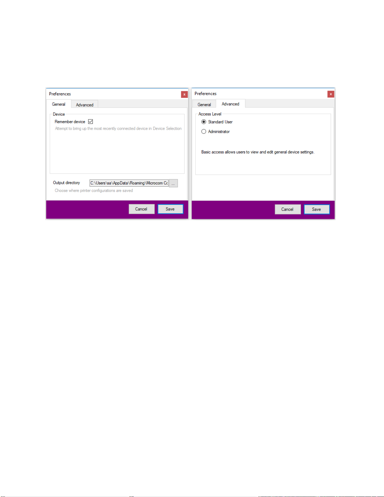
Application Preferences...............................................................................................8
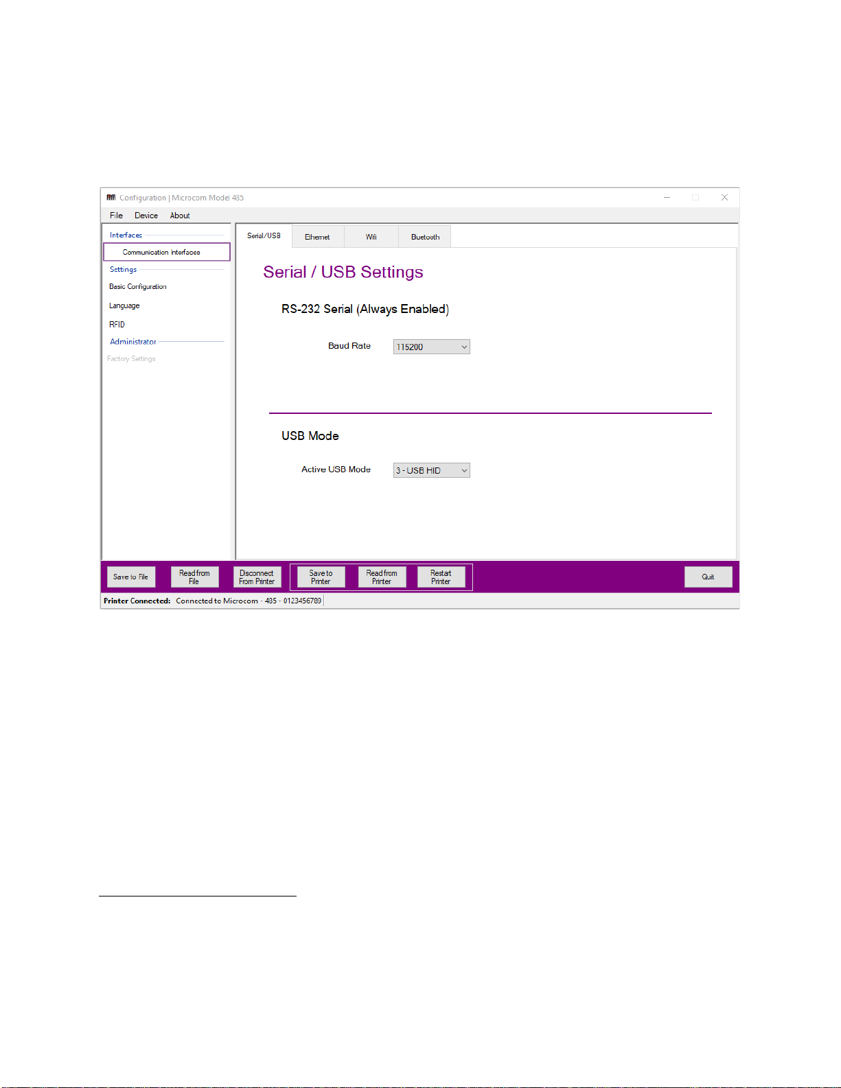
Communication Interfaces...........................................................................................8
RS-232 (Serial) ...................................................................................................................8
USB Mode...........................................................................................................................8
Ethernet..............................................................................................................................8
Wi-Fi ...................................................................................................................................9
Bluetooth...........................................................................................................................11
Basic Configuration ...................................................................................................11
Language and Document Settings ............................................................................13
FGL Mode......................................................................................................................... 13
Image Mode......................................................................................................................15
LDS2 Mode.......................................................................................................................16
RFID..........................................................................................................................16
Factory Settings (Administrator)................................................................................17
Troubleshooting.........................................................................................................18

Overview
The 485 Configuration Application allows you to easily configure the settings of a Microcom 485
printer. You have the freedom to save and read configurations independent of a printer
connection. Once a printer is connected, you can save or read configurations directly to or from
the printer, respectively. You can then restart the printer directly from the application and
connect to a different device immediately afterwards. Hover over parameter labels for a brief
description on its purpose.
Installing the application
The 485 Configuration Application and its dependencies are installed by running the provided
setup utility. Most modern versions of Windows require Administrator privileges to perform this
type of installation.
Run Microcom485ConfigurationAppSetup_x86.exe.
The setup utility will guide you through the installation process. Take note of the installation
directory. By default, application package files will be placed in either the “C:\Program Files” or
“Program Files (x86)” directory.

Configuration Window
Upon startup, the application immediately opens up to the configuration window. The window is
made up of three panels: the configuration categories (left), configuration values (right) and
control buttons (bottom). The values are populated with default parameters that you can be
changed. You can easily read from file previous configurations, save to file the current
configuration or connect to a printer.
FIGURE 1: CONFIGURATION WINDOW
Saving and Reading Configuration Files
A configuration file is generated by the application when the Save to File button is clicked, or
when the File->Save Configuration menu (top) option is selected. Clicking either of these two
options will open a Windows Save As dialog in the application output directory
1
. A unique
filename is generated by default to avoid overwritten configurations.
To read a previously saved configuration file, click the Read from File button or the File->Load
Configuration menu option. The application will open a file dialog in the application output
directory. Select a configuration file, and click “Open” to update the on-screen controls with the
configuration values contained in the file. Note that loading a file does not send the
configuration to the printer until a printer is connected and Save to Printer button is clicked
2
.
1
The default location for the application output directory is
C:\Users\<username>\AppData\Roaming\Microcom\485\Saved_PrinterConfigurations . The output
directory can be changed in the application preferences.
2
When loading a configuration from a file and saving to printer, proceed with caution as you could
accidentally overwrite settings that could cause problems with the printer. The application will ignore any

Configuration files created outside of the application can also be read regardless if all
parameters start with *MXF or *MXS.
Connect/Disconnect Printer
To connect to a printer, click Connect to Printer button. The Device Selection Window will
appear and you can choose the interface in which to connect to the printer. Once connected,
the buttons Save to Printer, Read from Printer and Restart Printer will appear. The same
button will now display “Disconnect from Printer”.
To disconnect to the printer, press the same button and the connection with the printer will be
closed. The button will now display “Connect to Printer”. The buttons Save to Printer, Read
from Printer and Restart Printer will disappear.
Save to Printer
To apply all configuration changes to the printer, click the Save to Printer button. This will send
all the current values held by the on-screen controls to the connected printer. The printer must
be restarted for the changes to take effect. A restart can be performed by clicking the Restart
Printer button or by manually turning off and on the power switch on the printer. When the
printer reboots, the changes will be in place.
Note: Settings that cannot be saved to the printer from the configuration application include –
Model, Printer Firmware Version, Serial Number, CPU Serial Number and MAC Address.
Read from Printer
To read the configurations currently saved on the connected printer, click the Read from
Printer button. The values will populate the on-screen controls.
factory parameters read from a file so the corresponding controls will not update for those values.
However, the application will always read every parameter read from a printer including the factory
settings.

Selecting a Device
To connect to a printer, click Connect to Printer. This opens up the Device Selection Window
to connect the printer via four possible interfaces. The interfaces are RS-232 serial, USB serial,
USB HID and Network. With the exception of RS-232, all of these interfaces can be
enabled/disabled on the printer. To determine which interfaces are enabled, a diagnostic label
can be printed by powering down the printer and powering it back on while holding the front
panel button OR by pressing the front panel button while in FGL mode. Once you know which
interface to use, select it on the left panel, choose it from the selection list on the right, and click
OK.
If you are experience trouble connecting, power up the printer with the push button held in. This
will put the printer into diagnostic mode which ensures a response during connection.
Additionally, it will change the USB Mode into USB HID so there is a way to connect even if the
interface or IP Address is unknown. The printer will revert back to its initial USB Mode on restart
unless it was changed in the configuration application.
FIGURE 2: DEVICE SELECTION WINDOW
Serial (RS-232/USB CDC)
RS-232 and USB CDC (USB serial) connections will be recognized as COM devices by
Windows
3
. Typically, more than one COM device will be found by the application. To
determine which COM port is bound to the Model 485, check the ‘Devices and Printers’ menu in

the Windows Control Panel. Choose the appropriate COM port to make RS-232/USB CDC the
active interface.
USB HID
A USB Human Interface Device (USB HID) is a generic classification of an input device.
Windows comes pre-loaded with the USB HID drivers necessary to communicate with the
Model 485, which means there is nothing for the user to install.
As is the case with COM devices, the 485 Configuration Application will typically find more than
one USB HID device. Luckily, Microcom printers are identified as such and will be listed as
“Microcom - <Model> - <Serial Number>”. For example, the device selection box would list a
Microcom 485 as “Microcom - 485 - 123456”. Choose the desired printer from the selection list.
If more than one Microcom 485 is connected to your computer and you do not know the serial
number, press the push button on the printer to print a test ticket while in FGL mode.
Network
If your Microcom 485 and computer share a network connection, the 485 Configuration
Application can use the printer IP address and port to communicate
4
. Enter the IP Address and
Port that the printer is configured to listen on. If you do not know the port or the IP Address,
press the push button on the printer to print a test ticket with this information (FGL mode only).
The default IP Address and port are 192.168.200.3 and 9100, respectively.
4
If you have a Wi-Fi-equipped Microcom 485 printer, select Ethernet in Device Selection to configure the
printer over Wi-Fi by entering the wireless IP address and port.

Application Preferences
The Preferences window can be accessed by selecting File->Preferences from the menu bar.
Within the preferences you can:
1. Change the configuration file output directory
2. Remember device –attempt to bring up the most recently connected device
3. Change between Standard User or Administrator (with password)
FIGURE 3: PREFERENCES WINDOW
Communication Interfaces
This tab provides a way to configure all of the printer’s communication interface parameters.
The interfaces include RS-232, USB Mode, Ethernet, Wi-Fi and Bluetooth. These are all the
ways that a printer can connect with a host machine to execute print jobs.
RS-232 (Serial)
This interface is always enabled and the only parameter available to configure is the Baud Rate.
The baud rate determines the speed the data is transferred between the host and the printer.
The recommended speed is 115200 bits per second.
USB Mode
The user can choose to change the active USB mode between Disabled, USB CDC (emulates
serial over USB), USB HID and USB PRN. The USB mode can be enabled while any other
interface is also enabled. Both USB CDC and USB HID are supported by Windows so the
printer can easily be detected once plugged in. It is recommended that USB PRN be set only if
the printer is going to be connected to a Linux machine. Otherwise, the printer will be unable to
connect on a Windows machine since there is no USB PRN driver support.
Ethernet
The Ethernet interface can be enabled or disabled. While disabled, the user will be unable to
connect to the printer via Ethernet but all auxiliary services such as the 485 Webpage Interface
will still be functioning and accessed through the Ethernet.

It is recommended to keep DHCP enabled which means the printer will use the DHCP protocol
and acquire an IP Address for itself. As a result, the static IP address values set in the boxes
below it will not be the printer’s active address and will not be applicable when connecting via
Ethernet. However, if the DHCP protocol fails to assign an address to the printer after 1 minute,
the printer will take on the static IP address. If DHCP is disabled, the printer will automatically
apply the static IP Address displayed below upon boot up.
FIGURE 4: ETHERNET SETTINGS
Wi-Fi
Wi-Fi settings are available regardless if the printer connected is Wi-Fi equipped. By default,
printers without Wi-Fi capability will have the Wi-Fi interface parameter disabled and any values
saved to the printer in this category will not have any effect on the device. If Wi-Fi is enabled,
the printer can be configured for either Access Point Mode or Join Mode. For a full description
on Wi-Fi, please refer to the 485 Wifi User Guide.
If the mode is set to Access Point, the printer will act as a “hotspot” for other devices to connect
to. Its Broadcast ESSID and Password can be configured to control who can access the printer
wirelessly. Passwords are required to be between 8-16 characters long.

FIGURE 5: WIFI –ACCESS POINT MODE SETTINGS
If Join Mode is selected, the printer can connect to an existing Wi-Fi network by entering its
information in the provided fields. It is recommended to enable DHCP and have Encryption set
to WPA2/PSK.
FIGURE 6: WIFI –JOIN MODE SETTINGS

Bluetooth
Bluetooth settings are available regardless if the printer connected is equipped with the
Bluetooth dongle. By default, printers without Bluetooth capability will have the Bluetooth
interface parameter disabled and any values saved to the printer in this category will not have
any effect on the device. For a full description on Bluetooth, please refer to the 485 User Guide.
FIGURE 7: BLUETOOTH SETTINGS
Basic Configuration
The basic configuration page provides miscellaneous printer parameters to adjust or edit. If a
printer is connected, the model and firmware version will appear at the top of the page.
Configurable parameters include:
Cutter Type
Cutter Speed (Forward & Reverse)
Stock Eject Distance
Network Timeout
UDP Discover
Enable Line Printer Daemon (LPD)
Stock Sensitivity (Black Mark & Gap)
Sensitivity (Black Mark & Gap)
Dual Sensor Gap Detection
Dot History
Enable Web server
Webpage Refresh

FIGURE 8: BASIC CONFIGURATION SETTINGS

Language and Document Settings
The language and document settings offers the ability to switch the boot language between
FGL Mode for ticketing use , Image Mode to use with the Windows Driver and LDS2 Mode. The
printer can only have one boot language but all values set in any language mode pages will be
sent and saved to the printer regardless of which language is chosen. However, only the values
corresponding to the enabled boot language will take effect in the printer.
FIGURE 9: LANGUAGE AND DOCUMENT SETTINGS
FGL Mode
FGL Mode is used for ticketing and includes its own set of FGL specific parameters. It is
separated into general parameters and document parameters. These settings generally are
used to change printer behavior.
General Parameters Include:
FGL File ID
FGL Storage Mode
FGL Print Intensity
FGL Low Voltage
FGL Logo Id
FGL SPH Ticket Width
FGL Speed
Cutter Enable
Cutter Offset
Multi-Ticket Mode
Special Font Mode
Test Button Enabled
Test Ticket Ack Enabled
Ticket Ack Mode

FIGURE 10: FGL PARAMETERS
It is generally recommended that Autosize is enabled. If enabled, the printer will automatically
calculate the Tag DRM value which overrides the value shown in the controls. However, in
some printers like RFID printers, it may be necessary to disable Autosize. Once disabled, all the
previously grayed out controls are enabled to adjust the size of the media accordingly.
There is also an inches to dots and vice versa converter. Typically, measurements are set and
stored in dots but that requires more advanced calculations. To make tag length configurations
easier, the user can choose to input the length in inches. Once you press Submit, the length in
inches will be converted to dots and the Tag DRM will also be calculated automatically. This
method is best used with standard FGL media. Otherwise, if the media is not standard, it is
recommended the user checks the “Input Length in Dots” box in order to manually input the
values for length in dots and Tag DRM for the best accuracy. Pressing Submit will convert the
length in dots to inches.
Note: the conversion and calculation will not occur until Submit is pressed. Whichever value is
displayed in the application when Save to Printer is pressed will be the value sent to the
printer.
FGL Document Parameters Include:
Autosize Enable
Autosize Speed
Detect mode
Left Margin
Top Margin
Tag Mark Length
Tag Length (Inches & Dots)
Tag DRM

Image Mode
Setting the printer to Image Mode will make it compatible with the Microcom Windows Driver.
Currently, all printer configurations are set by the driver while in Image Mode so this application
does not offer any specific parameters to configure.
The switch banks currently have limited support on the 485 Printer so it is recommended to
keep all values at zero.
FIGURE 11: IMAGE MODE PARAMETERS

LDS2 Mode
Currently the 485 Configuration Application does not have LDS2 Mode parameter support so if
LDS2 Mode is selected, there will be an empty screen.
FIGURE 12: LDS2 MODE
RFID
RFID (Radio Frequency Identification) is a module offered in specific models of the 485 Printer.
The configuration application includes RFID settings regardless if the printer connected is RFID
equipped. By default, printers without RFID capability will have RFID disabled and all RFID
related settings will have no effect on the printer.
RFID Parameters:
Retry Count –Number of retries to attempt if an RFID operation fails.
Timeout –Milliseconds the printer will wait for the RFID reader to respond to a single
command sent to it.
RFID Keys –Used to authenticate MIFARE 1K tags ONLY.
RFID Step Offset –Adjust the distance the media is retracted from the registration mark.
Distance = Retract Distance - Offset. Mainly used to adjust RFID wristbands

FIGURE 13: RFID SETTINGS
Factory Settings (Administrator)
Factory settings can only be accessed if the user goes to File->Preferences->Advanced,
checks “Administrator” and enters in the password correctly. These factory settings are set
during factory production and are not meant to be user configurable. Changing any of these
parameters may cause the entire printer to malfunction.

Troubleshooting
No Ethernet address is listed on the test ticket. Is
DHCP turned on? Is the cable plugged in?
DHCP is turned on, but I cannot connect to the printer.
Is the network connection you are plugged in to running a DHCP server? If yes, it might take a
few moments to assign the printer an IP address. If no, wait approximately 60 seconds and the
printer will assign itself a default IP address of 192.168.200.3.
When I press the push button, all that is printed are diagonal lines.
The printer is not in FGL mode, so the FGL test ticket is not printed. You can reboot the printer
with the push button held in to print a diagnostic ticket which contains mostly the same
information. This will help determine how to communicate with the printer.
During the installation, the progress bar is stuck on “Installing C++ Redistributables”.
This can sometimes happen during the installation process and could be caused by a number of
things. There are a few things to check out if this happens:
•Go to Windows Update and check that your OS is up to date.
•Go to Installed Programs and Features and see if the redistributable is already installed.
•Close the installer and try to run the 485 Configuration Application. Sometimes the progress
bar hangs even though the installation was successful.
Table of contents
Other Microcom Printer manuals

Microcom
Microcom 410 ECA User manual

Microcom
Microcom 326M User manual

Microcom
Microcom 465 User manual

Microcom
Microcom 426P User manual

Microcom
Microcom 428TM User manual

Microcom
Microcom 485TC User manual

Microcom
Microcom 324M User manual

Microcom
Microcom 322M User manual

Microcom
Microcom 405 Installation and operating instructions

Microcom
Microcom 485TM User manual

Microcom
Microcom 426M User manual

Microcom
Microcom 424 User manual

Microcom
Microcom 470 User manual

Microcom
Microcom 814M User manual

Microcom
Microcom 226 User manual

Microcom
Microcom 438TM User manual

Microcom
Microcom 424M User manual

Microcom
Microcom 334M User manual

Microcom
Microcom 224 User manual

Microcom
Microcom 428LT User manual