Microgate WITTI-TAB User manual

User Manual
Version 1.1

Microgate Witty TAB User Manual Page 2 of 33
Contents
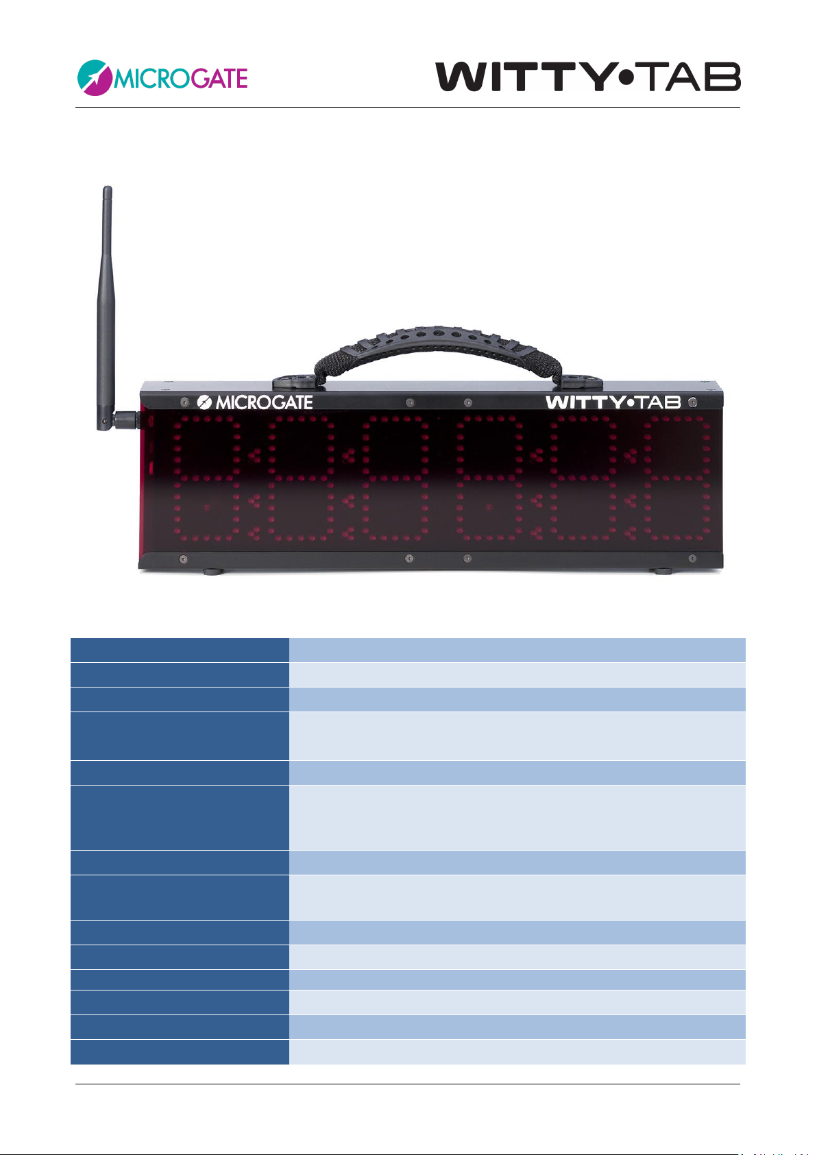
1Hardware............................................................................................................................................................. 4
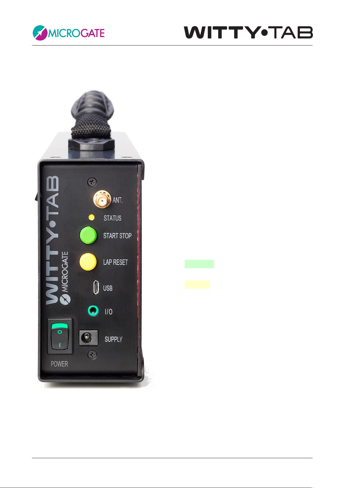
1.1 Control Panel........................................................................................................................6
1.2 Power Supply and Battery Charging ....................................................................................7
1.3 Photocells.............................................................................................................................8
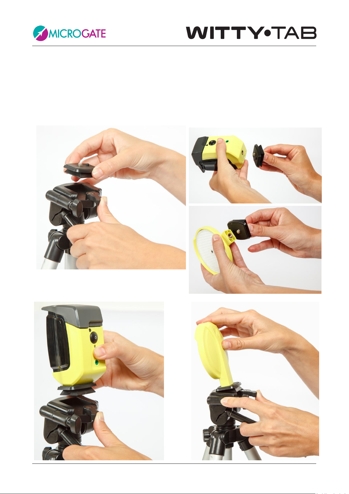
1.3.1 Mounting Photocells and Reflectors on Tripods .............................................................9
1.3.2 Statuses and Colors of the Photocell LED ......................................................................10
1.3.3 Paired Photocells............................................................................................................11
1.4 Radio System......................................................................................................................12
1.4.1 Duration of the Transmission Impulse (Radio Power)...................................................13
1.5 Use of the Display Board in Manual Mode........................................................................15
1.6 Brightness Sensor...............................................................................................................15
2Internal Programs ..........................................................................................................................................16
2.1 P0 –Start and Stop.............................................................................................................18
2.2 P1 –Start, Lap1, Stop.........................................................................................................19
2.3 P2 –Start, Lap1, Lap2, Stop ...............................................................................................19
2.4 P3 –Speed..........................................................................................................................21
2.5 P4 –Lap Speed ...................................................................................................................22
2.6 P5 –Start, Lapn, Stop.........................................................................................................23
2.7 P6 –Continuous Timing .....................................................................................................24
2.8 P7 –Starting System ..........................................................................................................25
2.9 P8 –Event Counter ............................................................................................................26
2.10 P9 - Parallel Event Counter ................................................................................................27
2.11 P10 –Date and Time..........................................................................................................28
2.12 P11 –Time..........................................................................................................................28
2.13 P12 –ReacTime..................................................................................................................28
2.14 P13 –Countdown...............................................................................................................28
2.15 P14 –Lap Time...................................................................................................................29
2.16 P15 - Witty·SEM .................................................................................................................29
2.17 P96 –Photocell Filter .........................................................................................................29

Microgate Witty TAB User Manual Page 3 of 33
2.18 P97 -LED Segments Test...................................................................................................30
2.19 P98 - Photocell Radio Signal Test.......................................................................................30
2.20 P99 –Parameter Configuration .........................................................................................31

Microgate Witty TAB User Manual Page 4 of 33
1HARDWARE
Figure 1 –Witty·TAB
Weight
2.9 kg, batteries included
Dimensions
13 x 41.5 x 6 cm (H x W x D)
Operating temperature
0° C/+45°C
Unit of time measurement
1/100 s
Selectable speed m/s –km/h –mph
Measurement resolution
4 x 10⁻⁵ s (1/25000 s)
LED matrix
Numerical: 6 digits x 7 segments (10 x 5 LEDs) with 4 punctuation
marks (full stop or colon) with manual/automatic brightness
adjustment.
Radio module
433-434MHz multi-frequency transceiver
Radio transmission
Digital FSK transmission; redundant code with information
correctness verification and auto-correction
Radio frequencies
433.1125 MHz to 434.7375 MHz
Radio transmission power
10 mW
Radio transmission range
Approx. 150 meters
Processing unit
16-bit microcontroller
Time base
12. quartz 8 MHz, stability ±10ppm between 0°C and +45°C
Power supply
Two internal Pb batteries

Microgate Witty TAB User Manual Page 5 of 33
Battery charging
Intelligent external Pb battery charger device
Battery life
> 10 hours
Buttons
•START/STOP button
•LAP/RESET button
Connections
•Type B MICRO USB connector to connect to a PC
•Jack connector for external input/output
•SMA connector for connection to an external aerial

Microgate Witty TAB User Manual Page 6 of 33
1.1 CONTROL PANEL
Figure 2 –Control panel
ANT: radio aerial connector
STATUS: status signal LED.
START STOP: Green START STOP button used
for manual START and STOP signals and for
modifying values in program settings1
LAP RESET: Yellow LAP RESET button used for
manual LAP signals and for confirming program
settings2
USB: USB cable connector for firmware
updating
I/O: 3.5 mm jack for external sensors, such as
starting pads, start gun sensor, button, etc.
POWER: On/Off switch
SUPPLY: Connector for external power supply
and battery charging
1This button will hereafter be referred to as
START-STOP
2This button will hereafter be referred to as
LAP-RESET

Microgate Witty TAB User Manual Page 7 of 33
1.2 POWER SUPPLY AND BATTERY CHARGING
Witty TAB comes with two internal lead batteries ensuring an average 10-hour life. The status LED
on the side panel indicates the state of the battery (see table below).
To recharge the display board (or for mains-operated use) connect the power adapter to the
Supply socket and to the outlet. A LED on the power adapter (see below) allows monitoring the
charging process, which is approximately 5 hours.
STATUS
STATUS LED on WITTY·TAB
NORMAL Mode
•Battery charged
•Low battery
•Battery completely empty (LED matrix turned off)
Green - steady light
Red - pause
Red - steady light
BOOTLOADER Mode
•Witty•TAB has been turned on with the ON/OFF
switch by keeping the two buttons (“START STOP” and
“LAP RESET”) pressed
Red - Green
The LED on the power adapter indicates the following statuses:
STATUS
STATUS LED on the POWER ADAPTER
•Charging
•Charged/maintenance
Yellow
Green

Microgate Witty TAB User Manual Page 8 of 33
1.3 PHOTOCELLS
To switch on the photocell press the ON button for one second; the status LED blinks with a green light (if
the battery status is sufficient) or with an orange light (if the battery status is low). A continuous beeping
sound is produced until the correct alignment with the reflector (or a similar reflecting surface) is found.
To switch off the photocell press the button until the LED turns red, then release it.
ON/OFF button
USB connector for charging
and updating the firmware
3.5mm jack for photocell
pair and external inputs
Status Led

Microgate Witty TAB User Manual Page 9 of 33
1.3.1 MOUNTING PHOTOCELLS AND REFLECTORS ON TRIPODS
To mount the photocells and the reflectors on the tripods supplied with the kit, proceed as follows:
Take the little platform off the tripod's top and screw it onto the photocells and below the reflectors (the
platform is square-shaped and therefore allows 4 mounting directions with respect to the tripod). Mount
the devices onto the top of the tripod inserting the front of the platform, and then the rear until the tab
clicks into place.

Microgate Witty TAB User Manual Page 10 of 33
Extend the tripod legs to the required height (usually the photocell must be interrupted by the chest of an
athlete), and position the photocells and the reflectors at a distance of 1-7 meters.
1.3.2 STATUSES AND COLORS OF THE PHOTOCELL LED
PHOTOCELL OFF
STATUS
STATUS LED
•Battery charged/empty
Off
•External supply
•Battery charging
Orange blinking light
•External supply
•Battery charging
completed
Green steady light
PHOTOCELL ON
STATUS
STATUS LED
NORMAL Mode
•Battery charged
•Battery empty
Green - Pause
Red - Pause
BOOTLOADER Mode
•The photocell has not been switched on pressing the
ON/OFF button but connecting the USB cable to a PC. This
activates the BootLoader HID and the firmware can be
updated.
Red - Green
CONFIGURATION Mode
•When switching on, the ON/OFF button is pressed for at
least 5 seconds and the configuration mode is activated.
Red blinking light
TWO PHOTOCELLS Mode:
Master photocell (higher serial number)
•Battery charged
•Battery empty
Slave photocell (lower serial number)
•Battery charged
•Battery empty
Green - Pause
Red - pause
Green fast blinking light
Red fast blinking light

Microgate Witty TAB User Manual Page 11 of 33
1.3.3 PAIRED PHOTOCELLS
To prevent the photocell being interrupted by an athlete's arm swinging forward, in official
competitions or in any case when measurement must be as precise as possible, the use of paired
photocells is necessary.
This setup ensures that time is measured exactly when the athlete's chest crosses the line, as the
impulse (start/stop/lap, depending on the position) is given only when both photocells are
interrupted.
To mount the photocells, screw the C bracket onto the tripod platform, the photocells, and the
reflectors, as shown in the figure (the photocells are mounted at 90° with respect to the C
bracket).
Then mount the bracket onto the tripod and connect it with the photocells using the jack-jack
cable. The MASTER photocell is the one with the higher serial number and blinks more slowly than
the SLAVE. As the Master photocell transmits the signal to the timer, to ensure a wider aerial
range, the latter should always be mounted on top.
Master:
Higher S/N,
blinking at regular
speed.
Always on TOP!
Slave:
Lower S/N,
blinking fast.

Microgate Witty TAB User Manual Page 12 of 33
1.4 RADIO SYSTEM
The Witty·TAB display board communicates with the Witty photocells via 433Mhz radio
transmission with a maximum range of 150 meters in standard conditions. To prevent frequency
collisions with other Witty·TAB Kits on the field, it is possible to change the transmission channel
(of both the timer and photocells, which must have the same channel). Please refer to chapter
2.20 for information about changing the channel number.
In case of rainy weather radio transmission can be disturbed by the water drops and therefore the
maximum distance must be reduced.
For excellent reception, position the Witty·TAB display board at a height of at least 50 cm (without
it touching the ground) and do not place it on top of metal objects.
START STOPLAP1 LAPn
Wireless Radio Transmission
Max 150 mt.

Microgate Witty TAB User Manual Page 13 of 33
1.4.1DURATION OF THE TRANSMISSION IMPULSE (RADIO POWER)
To increase radio transmission reliability, photocell impulse data packages are transmitted
repeatedly over a set time of 1.2 seconds. This ensures that, in case of data loss, redundant
information can be used to rebuild the event with absolute precision.
If more than 1.2 seconds pass between two impulses (e.g. start and stop photocell) there will be
no problems, of course.
Start Stop
2,5 sec (> 1.2)
Trasmission of STA for 1,2s Trasmission of STO for 1,2s
STO FrameSTA Frame
Even if the distance is shorter, the second impulse will be detected anyway, as its "tail" will be
longer than that of the previous one.
Start Stop
0,8 sec (< 1.2)
Trasmission of STA for 1,2s Trasmission of STO for 1,2s
STO Frame
STA Frame

Microgate Witty TAB User Manual Page 14 of 33
Problems may arise when intermediate times (Laps) are used and these are very close to each
other or between start and stop. Again it is not necessary that the delta (difference) between the
impulses be more that 1.2 s; it is enough that the impulse has a "period of time" (green line)
during which it does not overlap with others.
STO Frame
Start L1
0,8 sec (< 1.2)
Trasmission of STA for 1,2s Trasmission of L1 for 1,2s
Stop
Trasmission of STO for 1,2s
0,6 sec (< 1.2)
STA Frame
L1 Frame
If there are many close intermediate times, one of them might be "completely" obscured by the
previous or following impulses (as in the case of L2 in the figure below) and therefore won't be
detected.
Start L1
0,8 sec (< 1.2)
Trasmission of STA for 1,2s
Trasmission of L1 for 1,2s
Stop
Trasmission of STO for 1,2s
STA Frame
L1 Frame
STO Frame
0,6 sec (< 1.2)
L2
0,5 sec (< 1.2)
Trasmission of L2 for 1,2s
L2 Frame

Microgate Witty TAB User Manual Page 15 of 33
1.5 USE OF THE DISPLAY BOARD IN MANUAL MODE
The display board can be used in manual mode using the two buttons on the side panel:
GREEN START-STOP button: Simulates a START or STOP impulse
YELLOW LAP-RESET button: during a “running time” it simulates a LAP impulse; when the timer is
stopped the display board is reset to the starting time
1.6 BRIGHTNESS SENSOR
Display board LED brightness can be set manually (from the menu) or assessed automatically
depending on the ambient light detected by the brightness sensor in the lower part of the first
digit. There is another sensor on the fourth digit, but only the one in the upper left corner is used
for active control.
The manual minimum/maximum brightness values range from 0 to 100% at 5% steps (see program
99)

Microgate Witty TAB User Manual Page 16 of 33
2INTERNAL PROGRAMS
The Witty·TAB display board also has a series of internal programs for various needs in athletic
performance evaluation.
The programs available at the time of printing this guide are:
#
Name
Description
P0
Start, Stop
Basic timing with auto reset after 5 seconds
P1
Start, Lap1, Stop
Basic timing with 1 intermediate time
P2
Start, Lap1, Lap2, Stop
Basic timing with 2 intermediate times
P3
Speed
Speed measurement based upon any length between two
photocells
P4
Lap Speed
Lap speed measurement with one photocell
P5
Start, LapN, Stop
Basic timing with n intermediate times and configurable
display time
P6
Continuous Timing
Continuous timing, configurable "dead time"
P7
Starting System
Start and Stop with reaction time at start
P8
Event Counter
Counter increasing automatically with each impulse
P9
Parallel Event Counter
Two counters (left and right) for two photocells
P10
Date and Time
Displays date and time
P11
Time
Time display
P12
ReacTime
Shows reaction time from the Lynx ReacTime device
P13
Countdown
Displays a countdown
P14
Lap Time
Displays lap times
P15
Witty·SEM
Use the Witty·Tab with the Witty·SEM system
P96
Photocell filter
Configure a filter to work with certain photocells
P97
LED Segments Test
Checks that the LEDs work correctly
P98
Photocell Radio Signal Test
Checks the correct radio transmission functioning
P99
Parameter Configuration
Configuration of the brightness, radio channel and date &
time parameters
To change program follow these steps:
•Keep the YELLOW LAP-RESET button pressed for at least 3 seconds.
•The currently selected program is displayed.
•Press the GREEN START-STOP button to scroll down the above-listed programs.

Microgate Witty TAB User Manual Page 17 of 33
•Once the desired program has been reached, press the LAP-RESET button to confirm.
•Depending on the chosen program, further settings may be required or the program is
executed immediately.
To change the parameters of a particular setting use the GREEN START-STOP button to increase
digits one by one every time you press it, keep pressed to scroll ahead. When inputting 3-digit
parameters (0-999), counter scrolling speed increases after 99.

Microgate Witty TAB User Manual Page 18 of 33
2.1 P0 –START AND STOP
Basic timing program. The impulse of the first photocell starts the running time; the second
impulse stops the timer, and the final time is displayed for 5 seconds, finally time is reset. To reset
the display board without waiting 5 seconds, press the yellow LAP-RESET button.
No particular photocell configuration is needed (the first impulse is the start impulse, the second is
the stop impulse).
START STOP

Microgate Witty TAB User Manual Page 19 of 33
2.2 P1 –START,LAP1, STOP
Similar to the previous but with the addition of an intermediate time. When the second impulse
(Lap1) is received, the display board displays the intermediate time for 5 seconds, then the
running time is shown again. The third impulse (stop event) has the final time displayed for 5
seconds and then automatically resets to zero.
START STOPLAP1
2.3 P2 –START,LAP1, LAP2, STOP
Similar to the previous but with the addition of two intermediate times. Both intermediate times
and the final time are displayed for 5 seconds.
START STOPLAP1 LAP2

Microgate Witty TAB User Manual Page 20 of 33
In the above-mentioned cases it is not necessary that the number of photocells be the same as
that amount of intermediate times, one photocell used as start/stop/lap is enough.
e.g. Lap time on an athletics track
Table of contents
Popular Industrial Monitor manuals by other brands

Rockwell Automation
Rockwell Automation Allen-Bradley 6186M-12PN installation instructions

Advantech
Advantech IDK-1115WP-45FHA1 user manual

Crystal Image Technologies
Crystal Image Technologies RMP-161-F21 user manual

BeiJer
BeiJer iX Panel T4A installation manual

Siemens
Siemens MTP700 Unified Comfort Quick install guide

red lion
red lion G304K2 manual