Micromark MicroLux 87776 User manual

Operating Instructions for
#87776 MicroLux®Multi-Saw
Dear Customer:
The MicroLux Multi-Saw is a high performance tool for every
model maker, and is ideal for the sawing of curves in wood,
plastic and non-ferrous metals.
State-of-the-Art production and testing procedures ensure
the maximum reliability from your power tool.
This manual comprises:
• Safety instructions
• Installation and operating instructions
• Spare parts list
• Warranty information
Reading this manual will:
• Help you understand the machine’s operation.
• Avoid malfunctions due to improper operation.
• Increase the life of the machine.
Always keep this manual close at hand.
Do not operate the machine unless you are fully familiar
with it. Please observe the safety instructions.
Use only original MicroLux spare parts.
Parts bags contain:
• 6 premium saw blades (2 each #80857 coarse, for wood
only; #87937 medium and #80856 fine, for wood, plastic
and non-ferrous metals)
• 1 machine screw and washer
• 3 wood screws
• 1 long Allen wrench
• 2 table clamps
• 1 vacuum attachment
• 1 small machine screw (for mounting to #81387 bracket)
Safety Instructions
Please read the following safety instructions thoroughly
and follow them before starting to work with the machine:
• eep the work area clean and tidy.
• Do not use electric tools in rain, under wet conditions,
near flammable liquids or gasses.
• Avoid contact with grounded parts, such as pipes,
radiators, cookers or refrigerators.
• Store tools out of the reach of children.
• Do not overload the machine.
• Do not wear loose clothes or jewelry.
• Do not carry the machine by the electric cable or yoke.
• eep the electrical cable away from heat, oil and sharp
edges. If necessary have it replaced by a specialist.
• Fasten the machine securely to a work table.
• Replace dull saw blades.
• Clean the machine thoroughly after completing your work.
• Pull out the electric plug before maintaining the machine,
before changing the saw blade or the toothed belt, or
when not using the machine.
• Make sure that the machine is switched off before
connecting it to the wall outlet.
• Check the machine for obvious damage before use.
Replace defective parts.
• Repairs in the electrical system should be carried out by
a specialist.
• Use only accessories and spare parts which are
recommended in these instructions.
• Use a push stick when working near the saw blade.

Legend Diagram
#1 Locking / Unlocking nobs for
Yoke Elbow and Foot Assembly
#2 Dust Blower Assembly
#3 Upper Clamping Ring
with Set Screw
#4 Foot Assembly
#5 Lower Clamping Ring
with Set Screw
Exploded View
#6 The 3 Locations for
Screw Mounting
#7 Speed Control Rheostat
#8 Power Switch
#9 C-Clamps Location
#10 Yoke Bow
#11 Blower Positioner Assembly
#12 Vacuum Adaptor
#13 Door Release Push Button
#14 Sliding Door
Machine Capacities
The MicroLux Multi-Saw cuts soft wood
up to 2" thick, hard wood up to 1/2" thick,
printed circuit boards and non-ferrous
metals up to 5/64" thick.
Note: Material thickness and hardness, plus blade
design and condition, will affect cutting speed.
Technical Data
• Number of strokes: continuously variable
between 500 and 1,700 per minute
• Stroke: .375" (3/8”)
• Motor: 110VAC, 1/10 hp
Dimensions
• Table: 6-1/4" square
• Distance from blade to neck of bow: 12"
Assembly and Set-Up Instructions
#1 After locating all of the components within the packaging and parts bags,
assembly begins by attaching the Yoke Bow (10) to the back of the saw
housing. This assembly uses the large phillips machine screw with its washer.
Please review the drawing at right.
You will be aligning the raised projection at the base and end of the Bow with
the Channel Notch located within the rear cut-out in the back of the housing.
First, place the saw on its face on a soft surface. Then, drop the assembled
machine screw and washer through the hole of the Bow section. Next,
engage the projection and notch until they feel fully seated. The screw should
be in alignment with the threaded hole at this time, and with a long barrel
#2 phillips screw driver, (with the driver held at an angle), engage the phillips
screw and secure the parts together. The 2 components are to be assembled
tightly and fully without any play.

#2 The Foot Assembly (4), arrives facing to the rear. Loosen
the nob (1) that secures it until you can spin it around to
face forward as shown in the Legend Diagram. Of note here
is the foot itself. It incorporates a grooved wheel that
supports the blade while material is being cut, thus keeping
your blade perpendicular to the table. The foot can be moved
forward or backward as required by loosening the 7mm hex /
phillips machine screw at the bottom of the assembly.
Loosen the Elbow Joint (10) nob and raise the Yoke for
clarification of this adjustment.
The Blower Positioner (11) comes mounted onto the right
side of the foot assembly. For your use, you can leave it
mounted in this location or disassemble it by removing the
knurled knob "A" and rearranging it to the left side. The
aluminum tube can be slid inside the assembly towards the
blade or away from it to allow clearance for the blade to be
installed later and at such an angle as to keep your cutting
line clear of dust. Attach the clear hose to the top of the
Blower Assembly (2) exhaust port located on the left side of
the head. It would be helpful to "wet" the port slightly
lubricating it and aiding in getting the hose over the port
opening. 3/32" is sufficient to hold it in place. See the
drawing at right.
#3 Blade Installation. This instruction sequence is lengthy,
but after you have done it 2 or 3 times, it takes less than
45 seconds to complete.
Select a blade you wish to use from the assortment included
with your saw. Installation of these premium blades begins
by pushing the button located on the right-side door inward
(13) and pulling the door (14) forward to remove it. See
drawing at right.
Locate the Lower Clamping Ring (5) inside. If this is the first
time you have ever used a MicroLux Mult-Saw, notice the set
screw on the ring that is facing you. This set screw will
secure your blade once installed. It should be just loose
enough from the factory to allow a blade to be inserted. If
not, you may need to loosen it with the provided Long Hex
ey. You will see shortly if you need to so. But, never loosen
it more than 2 turns, as it may fall from its position and then
have to be reinstalled.
At this point, you need to plug your saw into an outlet. The
2 switches located on the front panel of your saw power and
control the motor and reciprocating action. See Legend
Diagram (7) and (8). Rotate (7) counter-clockwise fully. This
will set your unit on its slowest speed reciprocation. Position
the saw so that you are comfortably viewing inside the right
side of your saw. You will only need to do this during the
initial set-up. While viewing inside, switch the power on and
view the action of the lower clamping ring. Now switch the
power off. You will now cycle the power on and off quickly,
until when off, the clamping ring is at the top of its stroking
action and nearest to the underside of the table. This may
take several attempts.

With the lower clamping ring in this position, you can set the
saw down on your table and begin installing your blade.
Loosen the Elbow nob one full turn and raise and lay the
head assembly backward. The lower clamping ring is visible
through the hole in the table top and the slit in the center of
it; here is where you will insert your blade. IMPO TANT:
For proper installation, the teeth of the blade must point
downward and at least 2 teeth should be below the top of the
table. With the premium blades provided, you can count on
4 to 6 teeth being below the table surface when fully inserted
into the slit of the lower clamping ring. Once oriented
correctly, slide the blank end of the blade into the slit until
you reach the bottom of the channel and the teeth are below
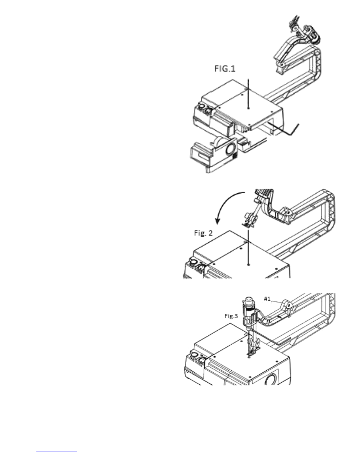
as explained above. Using the long end of the hex key,
tighten the set screw firmly with the blade straight up and
perpendicular to the table as shown in Fig.1.
Now refer to Fig. 2. Before you swing the head assembly
forward, remove the Upper Clamping Ring (3). Using the hex
key, loosen the set screw enough so that the Ring slips off of
the upper shaft. Lay the ring on the machine table top for a
moment. Flip the head assembly forward slowly and before
the grooved roller contacts the upright blade, manually bend
the blade forward, allowing it to make room for the assembly
until the head assembly is back down completely. Tighten
the Elbow nob.
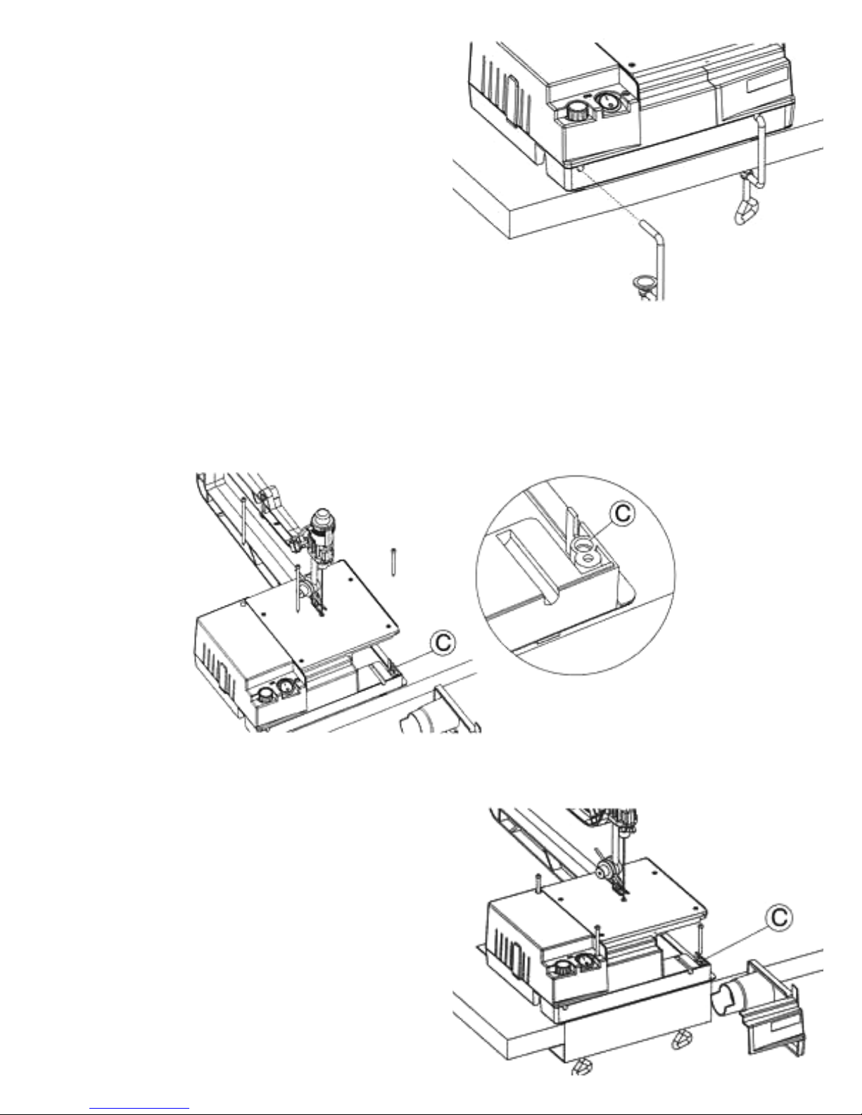
It is time to check the positioning of the black roller of the
foot. You want the back of the blade to be lightly in contact
within the groove of the roller. If adjustment is needed,
loosen the screw as described previously in section #2 and
slide it either away from or toward the blade.
A 7 mm hex wrench will work best, as you will not have to
raise the head assembly. Remember, the screw is upside
down to you and to loosen it you need to rotate it “clockwise”
in this position.
If all you have at this time is a phillips screw driver, you will
need to raise the head up, make your adjustment, and test
again by lowering the assembly onto the blade and keep
adjusting in this manner until it is where it needs to be. Each
time, you will need to secure the Elbow nob to check for
proper alignment.
Once adjusted, pull the top of the blade to the left or right of
the head and slip the Clamping Ring over and onto the
blade, allowing it to rest on the foot below.
There is a slit in the upper shaft. Manuever the blade into the
slit. Now, bring up the Clamping Ring, and with the set screw
to the right side, slide it fully up onto the shaft. The set screw
should line up with the indent on the shaft. Slightly secure
the set screw by hand with several turns until it stays in place.
Installation is almost complete. With one hand, push down
on the top black cap of the Dust Blower Assembly (2). You
will feel the inner shaft going down and coming into
contact with the top of the blade. At this point, tighten the
side set screw fully, clamping the blade in place. Note: Do
not push down beyond the point of just “in contact” with the
blade and cause the blade to bow to the side. Nor, do you
leave a large gap of contact. Once you feel it properly in
contact, use your other hand and the Hex Wrench to tighten
the screw fully. Installation is complete. See Fig.3.
Now with all items tightened and tools put away, turn on your
saw. The blade should move in a reciprocating motion without
binding, bumping, bowing or straining. Run through the full
speed range. Place a small piece of paper in front of the
aluminum blower tube and check the airflow. Power the saw
down. The next step is to secure your saw to a bench.

#4 To use the saw safely, accurately and successfully, and to
avoid vibration, the saw must be secured to a table or work
bench during operation.
Securing the saw is straight-forward and relatively easy.
There are 3 ways to do so:
Use the C-clamps provided, attaching them to the saw as
shown and tightening to table tops up to 1-7/8” thick. For
very thin table tops, add a wood spacer block between the
clamps and the underside of the table if necessary.
Optional mounting with Micro Mark #81387 Easy-Mount
Bench Bracket. The saw mounts to the bracket using the 2
long machine screws that are included with the bracket and
the small machine screw provided with your Multi-Saw.
Inserted the long screws into the 2 holes on the left side of
the saw. The small screw is inserted into the hole marked “C”
on the right side of the saw.
For permanent mounting, slide the 2 long screws through the top of the unit at the 2 marked locations (6) on the left side of the
housing. Use the the remaining small wood screw in the hole “C” indicated inside the right-side compartment.
For non-permanent mounting to a bench top, mount to a piece of 3/4” piece of plywood and then clamp to your bench with larger
c-style clamps to the left and right of the saw housing. Cut your plywood larger than the saw to allow for the larger clamps if you
use this method.

General Information
Speed Control
As a general rule, use slower speeds and finer blades (more teeth) for thin materials and metals. Plastics cut best using the slow-
est setting possible and with finer teeth. Use faster speeds and coarser blades (less teeth) for thick materials. Normally, woods
can be cut best at higher speeds. The best cutting experince is by trial and error and knowledge is gained over time.
Adaptive Foot Design
The foot should be adjusted to glide across the top of the
material being cut. This way, it will aid in keeping your material down against the table and prevent chattering while cutting.
Freehand Cutting
When cutting always be sure to keep material down against the table. Grip material firmly and feed slowly into the blade. If you
feed work too fast, blade may break or wander off the cutting line.
Blade Information, Quick Change
After your first experience of premium blade installation, future installation is a simple matter.
You do not have to cycle the machine and have the lower clamping ring assembly at its furthest upward position. You can do so, if
you prefer, if you need to see where the blade needs to enter the lower assembly. However, you can insert the blade into the
Lower Clamping Ring at any position if: You develop “the feel” of when it is inserted into the assembly correctly and fully and then
simply tighten the set screw as before.
However tall the blade sticks out of the base becomes irrelavant, as the machine is made to fit these premium blades and run
correctly. Bring the Upper Head Assembly down and around the protruding blade. Guide the blade into the upper slit as before and
with the use of the Top Black Cap push the upper assembly down to where it is “just contact” and you tighten the set screw…you
are ready to get back to work that quickly. Now, the benefits of the Elbow manufactured into the newly designed Yoke allows quick
maneuvering from one pre-drilled entry hole to the next for inside cutting!
Maintenace Information
Only use blades which are in good condition!
Replace blades when wear is apparent.
Always remove the plug from the wall outlet before
maintaining or cleaning the machine.
Occasionally place a drop of oil on the upper and lower shafts.
No other lubrication is required.
Do not leave the machine running while unattended.
Duty Cycle (Running Time) is 50/50. Meaning, use for up to
30 minutes and let cool for 30 minutes. If the machine ever
gets too hot from running excessively, components could be
damaged and cause the warranty to be voided. Please see the
warranty information at the end of this manual.
The vacuum adapater needs to inserted fully to make a secure
fit. Turning it as inserting it is helpful. Using a vacuum during
cutting is good practice with this saw.
Other blades can be used with this machine if they have the same amount of blank area at the bottom of the blades as the
premium blades have, at least 2 teeth are below the table surface, and the protruding blade is at the same height as that of a
premium blade. If the blade you would have liked to use does not come like this and cannot be trimmed like this, then the blade
should not be used.

LIMITED WA ANTY
Micro-Mark guarantees this product to be free of manufacturing defects for a period of 90 days from date of shipment, regardless of the amount of
time the product has been used and/or stored. The product, or parts thereof, will be repaired or replaced (at our option) and shipped back to you free
of charge if the following conditions have been met:
• the product is shipped back to us within the warranty period,
• incoming transportation charges have been pre-paid,
• proof of purchase has been provided, and
• our Service Department determines that the problem was caused by a defect in material and/or workmanship.
Please return to Micro-Mark Product Service Department at the address below with a note explaining the problem.
For products returned after the warranty period, our regular repair charges shall apply. Please include your telephone number so we may
advise you of the repair estimate. Any product returned to the purchaser without repair work being performed shall be shipped C.O.D. for the
return transportation charges.
This warranty does not cover damages resulting from improper assembly, adjustment or maintenance, accident, alterations, normal wear,
abuse or misuse, and does not apply where products are used commercially. The warranty shall also not apply when the product has been
used for purposes beyond those for which it was designed or unreasonable for its size.
Micro-Mark makes no other warranty of any kind whatever, expressed or implied, and all implied warranties of merchantability and fitness for a particular purpose which exceed the
above mentioned obligation are hereby disclaimed by Micro-Mark and excluded from this warranty.
This warranty gives you specific legal rights and you may also have other rights which vary from state to state. The obligation of the warrantor is solely to repair or replace the products.
The warrantor is not liable for any incidental or consequential damages due to such defect. Some states do not allow the exclusion or limitations of incidental or consequential
damages, so the above limitations or exclusion may not apply to you.
MM121517
Contact our
Product Service Department
at tech@micromark.com
Micro-Mark Product Service Department
340 Snyder Avenue
Berkeley Heights, NJ 07922
For replacement parts, contact our Technical Service Department
at tech@micromark.com and refer to the numbers in the diagram above.
Table of contents
Other Micromark Saw manuals
Popular Saw manuals by other brands

Porter-Cable
Porter-Cable 748 instruction manual

Invicta
Invicta RT-40 Operator's manual

Bosch
Bosch 3924-24 Operating/safety instructions

Jet
Jet SuperSaw JWSS-10CS Operating instructions and parts manual

Makita
Makita SH01ZW instruction manual

Craftsman
Craftsman 113.29401 Assembly, operating instructions and parts list

Bosch
Bosch PCM 1800 Instructions for use

DeWalt
DeWalt DW937 instruction manual

Greenlee
Greenlee Fairmont H4645 Operation, service and parts manual

Powermatic
Powermatic SLR12 Operating instructions and parts manual

Diamond Products
Diamond Products CC1113H Operator's manual

Scantool
Scantool 320 GSHE manual