manuals.online logo
Brands
  1. Home
  2. •
  3. Brands
  4. •
  5. MicroNet
  6. •
  7. IP Camera
  8. •
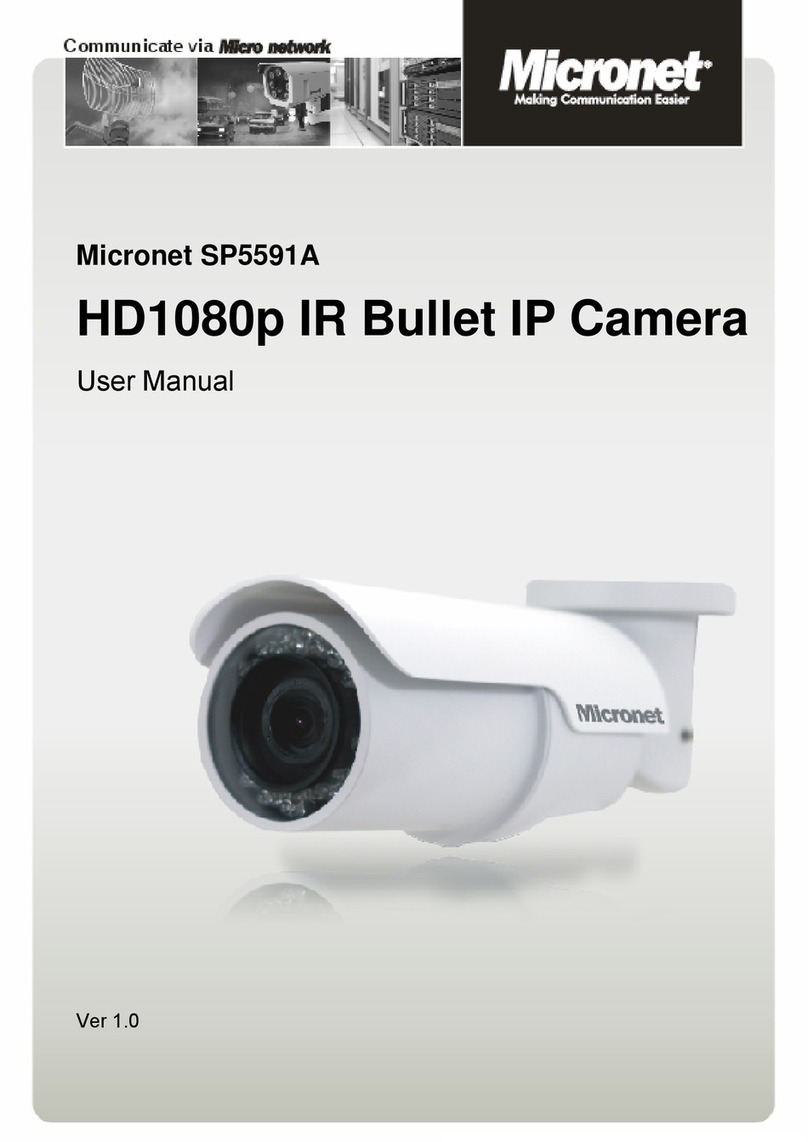
  9. MicroNet SP5591A User manual

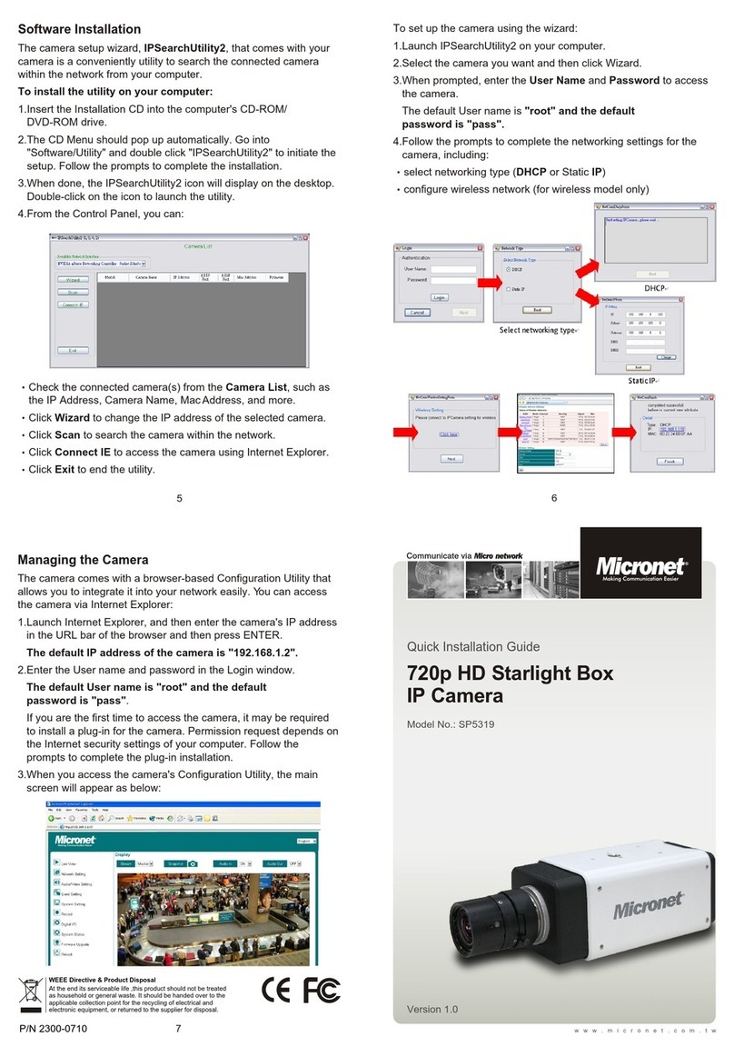
MicroNet SP5591A User manual

Communicate via
Quick Installation Guide
Model No.: SP5591A
P/N 2300-0740
6
5
7
WEEE Directive & Product Disposal
At the end its serviceable life ,this product should not be treated as
household or general waste. It should be handed over to the applicable
collection point for the recycling of electrical and electronic equipment, or
returned to the supplier for disposal.
Ceiling/Wall Mounting
Follow the steps below to install the IP Camera:
Step 1: Unpack the Bullet IP Camera package and take out the
IP Camera.
Step 2: Connect the power/Ethernet/alarm/audio wires from ceiling
or wall to the corresponding connectors of the camera's
All-in-one Cable.
Step 1:
Step 1:
Step 1:
www.micronet.com.tw
Step 2: Before Login to the Bullet IP Camera
A client program will be automatically installed on your PC when
connecting to the Bullet IP Camera. Before logging in to the Bullet
IP Camera, please ensure downloading the ActiveX control is
allowed by either changing the ActiveX controls and plug-ins or
setting Internet's security level to default. For further details, please
refer to the Bullet IP Camera's user manual.
Version 1.2
1080p Full HD Bullet IP Camera
Step 3:
Step 4: Use the supplied Inner Hex Wrench and
cross screwdriver to loosen the hex
bolt/screw on the side of the Bracket
Mount and the Camera Housing to
adjust the position of the IP Camera.
Fix the IP Camera's Bracket on the
ceiling/wall with supplied self
tapping screws
Step 3:
Step 3:
Step 3:
Step 3:
Step 3:
Step 3:
Lens Adjustment
Step 1: Unscrew the screw on the Camera
Housing and remove the Front Housing.
Step 2:
Step 3: Access the Camera Browser-viewer for viewing images.
Step 4:
Step 1:
Step 1:
Step 1:
Connect the power/Audio/alarm,
I/O wires to the matching connectors.
Adjust the Zoom/ Focus Ring Screw on the lens to set the
desired zoom/ focal length.
ActiveX Controls and Plug-ins
Settings
Step 1: Start the Internet Explorer (IE).
Step 2: Select <Tools> from the main
menu of the browser. Then
Click <Internet Options>.
Step 3: Click the <Security> tab and
select "Internet", and click
<Custom level> to change
ActiveX settings.
Step 4: Set "ActiveX controls and
plug-ins" items to <Prompt>
or <Enable>.
Step 2:
Step 2:
Step 2:
Step 2:
Step 2:
Step 2:
Step 2:
Internet Security Level
Step1: Start the IE.
Step 2: Select <Tools> from the main
menu of the browser. Then
Click <Internet Options>.
Step 3: Click the <Security> tab and
select "Internet."
Step 4: Down the page, press
"Default Level" and click "OK"
to confirm the setting. Close
the browser window, and
open a new one later for
accessing the Bullet
IP Camera
Step 2:
Step 2:
Step 2:
Step 2:
Step 2:
Step 2:
Step 2:
Step 2:
Step 2:
Step 3: Bullet IP Camera Login
The Bullet IP Camera's default IP address is: 192.168.1.2.
Therefore, to access the Bullet IP Camera for the first time, set the
PC's IP address as: 192.168.1.X; for example:
IP Address: 192.168.1.100
Subnet Mask: 255.255.255.0
Login ID & Password
Key in the Bullet IP Camera's IP address in the URL bar of the
Web browser window and press "Enter."
Enter the default user name (root) and password (pass) in the
prompt request dialogue. Note that user name is case sensitive.
Install the ActiveX control
After connecting to the Bullet IP Camera, the request for installing
the ActiveX control will appear just below the URL bar.
Right Click on the information bar, and press "Install ActiveX
Control..."to permit ActiveX control installation.
In the pop-up security
warning window, click "Install"
to start downloading DC
Viewer software on the PC.
Press "Finish" after DC
Viewer installation
is complete.
Browser-based Viewer
The main page of the Bullet IP
Camera user interface is as
shown below. Please note that
the function buttons will vary
depending on the camera model.
4
3
1 2
Package Contents
Please check the package contains the following items listed below.
Indroduction
Micronet SP5591A Full HD Bullet IP Camera is capable of serving
real-time streaming and makes image quality more smoothly. In
addition to MJPEG real time streaming, this camera develops H.264
codec to apply for high resolution digital broadcast.
With sophisticated mechanical design plus cable management, the
Full HD Bullet IP Camera is easy installed and aesthetic.
Features
Full HD 1080p with 2 Megapixel high resolution live
view and recording to see a particular spot in larger
and clearer image
Sony CMOS sensor for very high quality presence in
color and contrast
Multiple Stream such as H.264 and MJPEG provides
efficient bandwidth and save storage space
Motion Detection alerts when there is intruder
Privacy Mask keeps the personal spot that does not
want to be seen
WDR(Wide Dynamic Range) gives clear image even
when there is strong light in the background
3D Noise Reduction reduces the image noise to
enhance picture quality
Tampering Alarm sends picture alert when anyone
tries to remove the IP camera
ICR + IR LED allows monitoring at day time and night
time
IP66 Weather Proof designed for use in rugged
environments and adverse weather conditions
PoE 802.3af saves the trouble of a power source
Camera Connectors
Quick Guide
CD (bundled software
and documentation)
System Requirements
To perform the IP Camera via web browser, please ensure your PC
is in good network connection, and meet system requirements as
described below.
Items
Personal
Computer
Operating
System
Web
Browser
Network
Card
Viewer
System Requirement
®® ®TM
Intel Pentium M, 2.16 GHz or Intel Core 2 Duo, 2.0 GHz
2 GB RAM or above
Microsoft Internet Explorer 6.0 or above
Firefox, Chrome, Safari
10Base-T (10 Mbps) or 100Base-TX (100 Mbps) operation
ActiveX control plug-in for Microsoft IE
Windows XP / VISTA / 7
M4 Self Tapping Screws Plastic Screw Anchors
Power Terminal
Block
M4 Inner
Hex Wrench
5
1
Step 1: Bullet IP Camera Installation
Please follow the instructions below to complete Bullet IP Camera
installation.
Power up the Camera
To power up the Bullet IP Camera, please plug the DC 12V cable
into the Camera's power terminal block. Alternatively, connect the
Ethernet cable to the camera's PoE port and plug the other end of
the cable into a PoE switch.
NOTE: If using PoE, make sure Power Sourcing Equipment
(PSE) is in use in the network.
Ethernet Cable Connection
Connect one end of the CAT5e Ethernet cable to the RJ-45
connector of the Bullet IP Camera, and the other end of the cable to
the network switch or PC.
NOTE: In some cases, you may need to use an Ethernet
crossover cable when connecting the Bullet IP Camera
directly to the PC.
NOTE: Check the status of the link indicator and activity
indicator LEDs; if the LEDs are unlit, please check
LAN connection.
Green Link Light indicates good network connection.
Orange Activity Light flashes for network activity indication.
NOTE:
NOTE:
NOTE:
NOTE:
NOTE:
NOTE:
NOTE:
NOTE:
NOTE:
NOTE:
1
5
Bullet IP Camera
(Cable included)
1
2
Green
Pink
3
4
5
Cable
1 Alarm
2 Network
(with PoE)
3 Audio I/O
4 Power
5 BNC
Pin No.
1
2
3
4
_
Pink
Green
1
2
3
_
Definition
ALM_IN
ALM_IN
ALM_OUT
ALM_OUT
RJ-45 connector with LED
Line In/ Mic In
Line Out
DC 12V-1
GND
DC 12V-2
Analog Video Output
Remarks
Alarm connection
Power connection
Two-way audio
transmission
DC (-)
Reserved
DC (+)

Other manuals for SP5591A

1

Other MicroNet IP Camera manuals

MicroNet SP5563R User manual

MicroNet

MicroNet SP5563R User manual

MicroNet SP5923 User manual

MicroNet

MicroNet SP5923 User manual

MicroNet SP5319 User manual

MicroNet

MicroNet SP5319 User manual

MicroNet SP5584A User manual

MicroNet

MicroNet SP5584A User manual

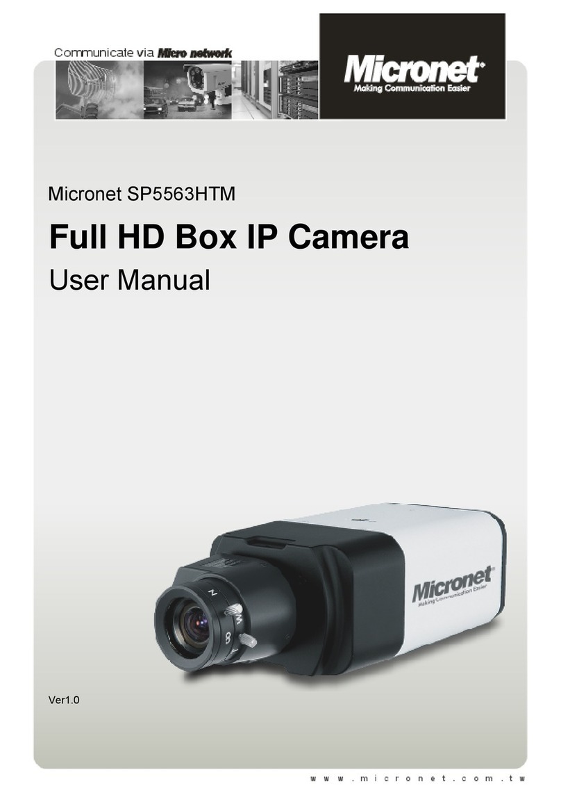
MicroNet SP5563HTM User manual

MicroNet

MicroNet SP5563HTM User manual

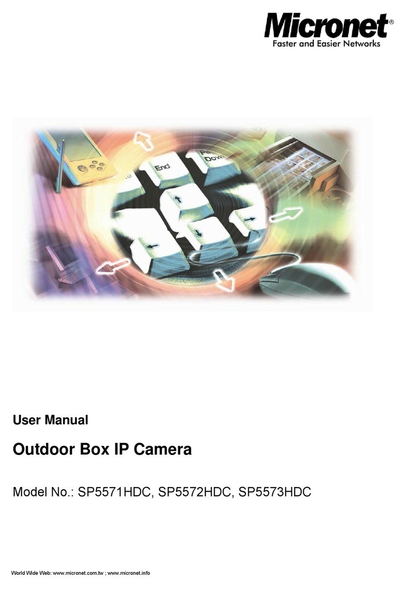
MicroNet SP5573HDC User manual

MicroNet

MicroNet SP5573HDC User manual

MicroNet SP5523W User manual

MicroNet

MicroNet SP5523W User manual

MicroNet SP5583HVM User manual

MicroNet

MicroNet SP5583HVM User manual

MicroNet SP5319 User manual

MicroNet

MicroNet SP5319 User manual

MicroNet SP5562HSM User manual

MicroNet

MicroNet SP5562HSM User manual

MicroNet SP5591A User manual

MicroNet

MicroNet SP5591A User manual

MicroNet SP5530 User manual

MicroNet

MicroNet SP5530 User manual

Popular IP Camera manuals by other brands

Dericam Sx Series user manual

Dericam

Dericam Sx Series user manual

AVer SF2121-BHR-30 installation guide

AVer

AVer SF2121-BHR-30 installation guide

Speco & IP-WDRB1 user manual

Speco

Speco & IP-WDRB1 user manual

RolloHomeControl 9483 instruction manual

RolloHomeControl

RolloHomeControl 9483 instruction manual

Marshall Electronics CV610-U3 user manual

Marshall Electronics

Marshall Electronics CV610-U3 user manual

Cisco PrecisionHD 1080p12x user guide

Cisco

Cisco PrecisionHD 1080p12x user guide

Honeywell HD4D3SX Quick install guide

Honeywell

Honeywell HD4D3SX Quick install guide

ZKVision ZKIR user guide

ZKVision

ZKVision ZKIR user guide

Spyclops SPY-MNBLTG1 manual

Spyclops

Spyclops SPY-MNBLTG1 manual

BOOM MAGNA quick guide

BOOM

BOOM MAGNA quick guide

Iqinvision IQeye 7 Series Quick install guide

Iqinvision

Iqinvision IQeye 7 Series Quick install guide

Cymbol G3 Series user guide

Cymbol

Cymbol G3 Series user guide

Avacom M1060W quick start guide

Avacom

Avacom M1060W quick start guide

Longse LIC120SSP manual

Longse

Longse LIC120SSP manual

EtroVISION EV6250A Series user manual

EtroVISION

EtroVISION EV6250A Series user manual

AVer FC1020-P Quick user guide

AVer

AVer FC1020-P Quick user guide

D-Link DCS-936L Quick installation guide

D-Link

D-Link DCS-936L Quick installation guide

TRENDnet TV-IP600W - Wireless Pan/Tilt/Zoom Internet Camera Server... Specifications

TRENDnet

TRENDnet TV-IP600W - Wireless Pan/Tilt/Zoom Internet Camera Server... Specifications

manuals.online logo
manuals.online logoBrands
  • About & Mission
  • Contact us
  • Privacy Policy
  • Terms and Conditions

Copyright 2025 Manuals.Online. All Rights Reserved.