Raytech Micro Junior 2 User manual

RAYTECH USA, Inc.
118 S. 2nd Street
Perkasie, PA 18944 USA
Tel. 888 4 THE SPY
Tel. 26 404 26 6
Fax. 26 404 2685
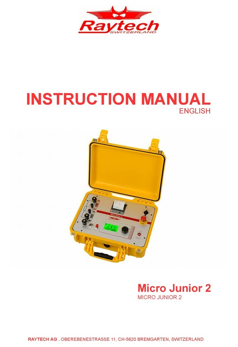
10 Amp Digital Micro-Ohm Meter
Model: Micro Junior 2
Instruction Manual Ver. 1.04

Raytech USA, Inc. All rights reserved. No portion may e reproduced without written consent 2
RAYTECH USA, Inc.
Table of Contents
0 – 1
Section Page
Table of Contents 0 – 1 2
Safety Precautions 1 – 0 3
Uncrating Procedure 2 – 0 4
Introduction
3 – 0 5
Technical Specifications
4 – 0 6
Front Panel Description
5 – 0 7
Front Panel Descript. Cont. 5 – 1 8
Front Panel Display screens
6 – 0 9
Screen Descriptions, Settings & Selections 6 – 1 10
Range Selection 10
Archive Menu 10
• Show 10
• Print 10
• Erase 10
Set Up Menu 11
• Clock Screen 11
• Interval Test 12
• Contrast 12
• Printer 13
Testing Screen Descriptions 6 – 2 13
Range Selection 13
• Single mode 14
• CONT mode (Continuous) 14
• AUTO mode (Automatic) 15
• INTER mode (Interval) 15
• Cross Current Measurements 16
Print Command 17
Store Command 17
System Details
– 0 18
Battery Check – 1 18
Li-Ion Charger – 2 18
Limitations of Testing – 3 19
Transformer Windings – 4 19
Low Resistance Testing – 5 19
Getting Started Quickly 8 – 0 20
Operation 8 – 1 20
Single, Continuous, and Automatic Modes 20, 21
Cross Current Measurements 8 – 2 21
Test Report 8 – 3 21
Troubleshooting 9 – 0 22
Warranty 10 – 0 23

Raytech USA, Inc. All rights reserved. No portion may e reproduced without written consent 3
SAFETY PRECAUTIONS!
1 – 0
The following safety precautions must e o served during all phases of operation, service, and
repair of this instrument. By purchasing this equipment the purchaser assumes all lia ility for the
operation and use of this equipment. The intended use of the instrument, its design and
manufacture, is to e conducted within the precautions or other specific warnings located within
this manual. Failure to comply with these precautions and other specific warnings violates safety
standards of design, manufacture, and intended use. Raytech assumes no lia ility for the
operation and use of this equipment.
SAFE OPERATION
Only qualified knowledgea le persons should e permitted or attempt to operate this test
equipment. All test personnel should fully familiarize themselves with the correct application and
operation of this and all test equipment prior to operation. Persons directly and indirectly
engaged in the operation of this test equipment should keep clear of all high voltage apparatus
while conducting tests and measurements.
BEFORE APPLYING POWER
Read this manual carefully efore operating the system. The Micro Junior 2 is attery operated.
The attery pack is charged via an external power supply which can handle input voltage from
100 to 240 vac 50/60Hz (auto-sense).
DO NOT OPERATE IN AN EXPLOSIVE ATMOSPHERE
Do not operate the instrument in the presence of flamma le gases or fumes.
KEEP AWAY FROM LIVE CIRCUITS
Operating personnel must not remove instrument covers. Component replacement and internal
adjustments must e made y qualified service personnel. Do not replace components with
power ca le connected. To avoid injuries, always disconnect power, discharge circuits, and
remove external voltage sources efore touching components.
DO NOT SUBSTITUTE PARTS OR MODIFY INSTRUMENT
Because of the danger of introducing additional hazards, do not install su stitute parts or perform
any unauthorized modification to the instrument. Return the instrument to a Raytech USA
service department for service to ensure proper operation and that safety features are maintained.
Instruments, which appear damaged or defective, should e made inoperative and secured against
unintended operation until they can e repaired y qualified service personnel.
TEST WARNINGS!
1. Do not use on live circuits.
2. Do not use test probes when testing inductive loads (Motors, transformers).

Raytech USA, Inc. All rights reserved. No portion may e reproduced without written consent 4
UNCRATING: 2 – 0
Unpack your new MICRO JUNIOR 2 and check to see that you have the following items:
Micro Junior 2
1
Manual + Current / - Current / Safety
Potential Potential Ground
Leads Leads Lead
Cable Carry Case Battery RS-232 Extra Roll
Charger Cable of paper
w/power cord
If any of the a ove items are missing or damaged contact your local representative or
Raytech USA, Inc. immediately.
RAYTECH Toll free service & support telephone: 1 888 4 THE SPY (888 484 3 9)
1. The Micro Junior 2 Fieldcase is a waterproof design that may incorporate a pressure relief valve. This
valve should e slightly open when encountering atmospheric changes; i.e... Airplane Travel, High
altitudes, etc... Close the valve when transporting the equipment in wet conditions.

Raytech USA, Inc. All rights reserved. No portion may e reproduced without written consent 5
INTRODUCTION 3 – 0
Raytech Digital Micro ohm meter, Micro Junior 2 was designed for high degree of accuracy for
the measurement of very low resistance. This technology was then packaged into a porta le test
system for use y apparatus manufacturers, re uild shops, and electrical maintenance crews.
Ease of use: This intelligent system has an easy to use operation screen, which allows quick
selection of the current level and resistance level to e measured. The system has the a ility to
reverse current flow automatically and provide extremely accurate results.
Impressive Accuracy: The Micro Junior 2 is a high precision, fully automatic, microprocessor
ased system. This system is designed for highly accurate readings on-site with la oratory precision.
Unique Measuring Technique: This newly designed technique of measurement incorporates a
high precision measurement circuit which will automatically measure with current flow in one
direction, then the system will reverse the current flow and display very accurate results to 0.1µ
Ohm. The system allows long term measurements at 10 amperes without frequent recharging.
Operation: The Micro Junior 2 applies a preset current level and resistance range selected y the
user. The results of the test are displayed within a few seconds automatically. The results are
reported on the easy to read liquid crystal display.
Compact Design: The Micro Junior 2 is a lightweight system that comes complete with its own
rugged waterproof Fieldcase.
Simple Maintenance: There is No maintenance required. There is No cali ration procedure (No
potentiometers to turn). This is due to the utilization of high precision components in the design.
Advanced Protection: Upon powering on the system initializes itself with a self-cali rating,
circuit checking sequence. If any pro lems are detected during this initialization period, or
during operation, the operator is immediately notified. The system constantly monitors the
condition when turned on. The Micro Junior 2 has extensive protection uilt in to the circuitry.
This is one of the many reasons we can extend our warranty to 5 years.

Raytech USA, Inc. All rights reserved. No portion may e reproduced without written consent 6
TECHNICAL
SPECIFICATIONS 4 – 0
MODEL: Micro Junior 2
SIZE: L: 16” (406 mm) W: 13” (330 mm) H: 7” (178 mm)
WEIGHT: 12.5 l s. (5.6 kg)
INPUT POWER: 100 to 250 Vac 50 / 60 Hz Auto-ranging attery charger
INTERNAL POWER: Lithium-Ion Battery, 14.8V / 6 Ah
TEST CURRENT: User Selecta le: 10, 1, 0.1, 0.01, 0.001 Ampere
PANEL DISPLAY: LCD Graphic with ack lighting
FRONT PANEL: Sealed anodized with a multi-actuation rotary kno
INTERFACE: 9 Pin RS232 Serial
MEMORY STORAGE: Internally stores up to 2000 complete test results
RESISTANCE RANGE:
0.1µΩ to 400kΩ
MEASUREMENT PARAMETERS:
Current Range Measuring Range Accuracy Resolution
10 Amp (A.F/R) : 0.1µΩ ... 40mΩ ± 0.1µΩ ± 0.1% Rdg 5 Digits or 0.01 µΩ
10 Amp : 1µΩ … 40mΩ ± 1µΩ ± 0.1% Rdg 5 Digits or 0.1 µΩ
1 Amp (A.F/R) : 1µΩ … 1Ω ± 1µΩ ± 0.1% Rdg 5 Digits
1 Amp : 10µΩ ...1Ω ± 10µΩ ± 0.1% Rdg 5 Digits
0.1 Amp : 100µΩ ...10Ω ± 0.1mΩ ± 0.1% Rdg 5 Digits
0.01 Amp : 1mΩ ...400Ω ± 1mΩ ± 0.1% Rdg 5 Digits
0.001 Amp : 10mΩ ...40kΩ ± 10mΩ ± 0.1% Rdg 5 Digits
0.001 Amp : 40kΩ ...400kΩ ± 10mΩ ± 1% Rdg 5 Digits
TEMPERATURE: Operating: -10° C to 60° C Storage: -20° C to 70° C
CABLE SET / ACCESSORIES:
Current and voltage lead set - 5 Meters, Ground Ca le, Power supply cord, Battery charger,
Instruction Manual, RS-232 ca le, and ca le ag.
MICRO JUNIOR 2 FEATURES:
• Microprocessor ased system
• Automatic measurements of Low Resistance
• Automatic current reversal mode for greater accuracy
• Internal storage for 2000 test results
• Response time less than 2 seconds
• Single push utton operation
• Automatic shut-off to extend attery life
• MJ 05 – Lithium Battery power source
• Runs for more than 5 hours continuous at 10 amps
• Complete automatic cali ration system
• Heavy duty protection circuitry
• Internal Panel Mount Printer
• External connection Port & RS232 (serial) Interface
• 5 Year standard warranty
MICRO JUNIOR 2 OPTIONAL ITEMS:
Part No - MJ 01 – Kelvin clip set
Part No - MJ 02 – Custom clamping devices (user specified)
Part No - MJ 04 – Kelvin pro e set
Part No - WR50-1A – External power supply (50A / 50V)
Part No - TP 02 – External Temperature pro e
* Specifications are su ject to improvement at anytime.

Raytech USA, Inc. All rights reserved. No portion may e reproduced without written consent 7
FRONT PANEL DESCRIPTION: 5 – 0
This is the power on switch. Turning the switch to the “ON” position applies power to the test set.
Turning the switch to the “OFF” position turns off the instrument. The switch defaults to the “Automatic off”
position and will automatically turn off after eing idle for a certain period (dependent upon attery charge).
Lithium Ion Charger Emergency OFF
Input Press to stop - Turn Clockwise to release
Earth Ground Terminal
External
This port is used for an external connection to the 50A/50V Transformer Winding Resistance
Power Supply Option: WR50-1A.
This port can also e used with an optional temperature pro e TP 02.

Raytech USA, Inc. All rights reserved. No portion may e reproduced without written consent 8
FRONT PANEL DESCRIPTION: Cont. 5 – 1
Test Connections:
+I = Positive Current connection
+P= Positive Potential (voltage) connection
-I = Negative Current connection
-P= Negative Potential (voltage) connection
Computer Connection:
Serial RS232 Computer and external serial printer connection
Buttons:
This is a multi-actuation rotary kno which is the main control and input.
This rotary kno allows the user:
To select the current and Resistance range.
To start a test sequence.
To store a test.
To put the test set into various measuring modes
To view Archive data (previous Test Reports saved into memory).
To print a test.
Printer:
This panel mount printer allows the user to print out stored results or current results.
The single utton on the printer is for Form-Feed.
To tear paper, pull paper towards the front of the instrument against the serrated cutting edge.

Raytech USA, Inc. All rights reserved. No portion may e reproduced without written consent 9
TYPICAL DISPLAY SCREENS:
6 – 0
START UP CURRENT & RANGE ARCHIVE
SELECTION HIGHLIGHTED
ARCHIVE ARCHIVE ARCHIVE
MEMORY LOC. SHOW MENU ERASE MENU
SETUP SETUP SETUP
HIGHLIGHTED MENU CLOCK
SETUP SETUP SETUP
INTERVAL TEST CONTRAST PRINTER
10A RANGE x 10A RANGE 10A RANGE
PRETEST REVERSE TEST AUTO. TEST
Further details of these menus and screens are located on the following pages.

Raytech USA, Inc. All rights reserved. No portion may e reproduced without written consent 10
SCREEN DESCRIPTIONS, SETTINGS & SELECTIONS:
6 – 1
RANGE SELECTION Screen:
Allows setting of Resistance & Current levels. Selection is made y turning the rotary kno to the
desired Current or Resistance range then pressing the rotary kno to confirm selection.
ARCHIVE Screens:
This is where the memory locations are kept.
In the RANGE SELECTION Screen, position the pointer with the rotary kno to highlight
“Archive”.
Press the rotary kno to view the Archive (memory locations) and this screen will appear:
SHOW: This selection allows viewing of all of the memory locations.
Press down on rotary kno to scroll through stored tests, the following screen will appear:
Press stop to revert ack to the previous screen.
PRINT: This selection will print the highlighted memory location.
Position the pointer with the rotary kno to highlight “SETUP” and return the RANGE SELECTION
screen.
ERASE: This selection will erase all of the memory locations.
Press “OK” to erase all of the stored results.
* If you do not wish to erase the stored results, position the pointer with the rotary kno to highlight
“STOP” and press the rotary kno to cease this action. *

Raytech USA, Inc. All rights reserved. No portion may e reproduced without written consent 11
SCREEN DESCRIPTIONS, SETTINGS & SELECTIONS:
6 – 1
SETUP MENU SCREEN:
Includes selections for Printer options, LCD Contrast, Interval Test mode and Clock adjustments.
In the RANGE SELECTION Screen, position the pointer with the rotary kno to highlight “Setup”.
Press the rotary kno to view the Setup options and this screen will appear:
This screen first displays:
Firmware (FW)
Serial Num er (SN)
Flash Boot Loader (FBL)
Selections are made y turning the rotary kno to highlight the desired position then pressing the
rotary kno for the desired selection.
CLOCK:
The time can e set y turning the rotary kno and pressing the desired selection. Selections are
made in this order: Year, Month, Day, Hour, and Minute.
Press the rotary kno while “Clock” is highlighted and this screen will appear:
You are now a le to adjust the Year, Month, Day, Hour, and Minute. Using the rotary kno , turn
clockwise or counter-clockwise to change the highlighted num er. Press the rotary kno to proceed
to the next num er.

Raytech USA, Inc. All rights reserved. No portion may e reproduced without written consent 12
SCREEN DESCRIPTIONS, SETTINGS & SELECTIONS:
6 – 1
INTERVAL TEST Screens:
The INTER (Interval Testing) mode will measure and store, automatically, numerous single
sequential tests at timed intervals that are preset y the operator. The test set measures continuously in
this mode.
In this INTER mode, the instrument will continuously measure multiple tests (current is always on)
until the operator selects and presses “Stop” or until the num er of tests that were pre-selected have
een achieved. The instrument will automatically save test results in a memory location that will
increment y the pre-selected timed interval.
While “Inter” is highlighted, press the digipot to pre-select a desired measurement setup:
Ti = Time Interval of Tests
N = Num er of tests to e performed
You are now a le to adjust the Time Interval. Using the digipot, turn clockwise or counter-clockwise
to enter the desired time. Once the desired Time is reached, press OK with the digipot. The following
screen will appear:
You are now a le to adjust the Num er of Tests. Using the digipot, turn clockwise or counter-
clockwise to enter the desired num er of tests. Once the desired num er is reached, press the digipot
to select “OK”.
* The minimum amount of time is 5 seconds, maximum of 10 minutes.
* The minimum num er of tests are 2, maximum of tests 2000.
CONTRAST Screen:
The Contrast (LCD) can e changed y pressing and then turning the rotary kno for the desired
view.
While “LCD” is highlighted, press the digipot. The following screen will appear:
You are now a le to adjust the contrast. Using the digipot, turn clockwise or counter-clockwise
to adjust the rightness or darkness of the screen.

Raytech USA, Inc. All rights reserved. No portion may e reproduced without written consent 13
SCREEN DESCRIPTIONS, SETTINGS & SELECTIONS:
6 – 1
PRINTER Screens:
This screen allows the user to select either the Internal panel mount Printer or external Serial Printer.
Internal – Default for the internal panel mount printer.
Serial – An external printer connected to the 9 Pin connector.
To change Printer setup, press digipot while “Printer” is highlighted. This screen will appear:
Using the digipot, scroll up or down to select the desired port. After printer or external port is
selected, press “OK” to return to the Range Selection Screen.
TESTING
SCREEN DESCRIPTIONS:
6 – 2
TESTING Screens:
RANGE SELECTION:
Test selections are initially made y turning the rotary kno to the desired selection of current or
resistance range then pressing the rotary kno to egin that sequence.
When the Micro-Jr 2 is first powered on the following RANGE SELECTION screen will appear:
Select the desired test range y turning the rotary kno . The pointer will turn to the availa le ranges.
Press the rotary kno when the desired range is highlighted to select that range.
The following Ranges can e selected:
<1 mA / Resistance range: 10Ω ...400kΩ
10 mA / Resistance range: 1Ω ...400Ω
0.1A / Resistance range: 100mΩ ...10Ω
1A / Resistance range: 10mΩ ...1Ω
x1A / Resistance range: 1mΩ ...1Ω
10A / Resistance range: 1mΩ ... 40mΩ
x10A / Resistance range: 1µΩ ... 40mΩ
* Note:
For the descriptions of the various adjustments and options for testing, this manual will use the
10A and x10A Ranges as examples on the following pages.

Raytech USA, Inc. All rights reserved. No portion may e reproduced without written consent 14
TESTING
SCREEN DESCRIPTIONS:
6 – 2
TESTING Screens: con’t.
10A Screen:
When the 10A range (or any other Range) is selected, the following screen will appear to allow the
user to select the type of test mode required:
SINGLE Test mode:
The system will conduct and run a single test on a device. The test measurement sequence
completes within a few seconds.
Selection of “Single” starts a test sequence. The following screen will appear:
Once the test has completed the user has the option to:
“GO” : Start another test.
“Store” : allows the user to save a reading into a memory location (Archive).
“Print” : allows the user to go to the print screen.
“Mode”: Select another test mode.
“Setup” allows the user to go to the Range Selection screen.
CONT (Continuous) Test mode:
Selection of “Cont” starts a continuous test sequence.
In the continuous test mode the test set will measure until the user selects and presses “Stop”.
The test system has an output of current that runs continuously while the resistance measurements
are eing taken. Selection of “Cont” starts a continuous test sequence. The following screen will
appear:
Note: The user can Select “Store” or “Print” at anytime that the system is measuring.
After the user Selects and presses “Stop”. The test sequence will halt. The user now has the a ility
to:
“Store” : allows the user to save a reading into a memory location (Archive).
“Print” : allows the user to go to the print screen.
“Auto” : allows a test to e made then automatically saves it in memory.
“Setup” allows the user to go to the Range Selection screen.

Raytech USA, Inc. All rights reserved. No portion may e reproduced without written consent 15
TESTING
SCREEN DESCRIPTIONS:
6 – 2
TEST Screens: con’t.
AUTO mode:
Selection of “Auto” allows a num er of tests to e made then automatically saved to memory.
When selected to egin this test the system prompts the operator to “Make Contact ” to the device
under test. The system automatically detects when the contact is made to the device under test and
egins the measurement sequence. After completion of the test the system saves the results in
memory then prompts the operator to “Open Contact” to the device. Once the contacts have een
removed from the device under test it is then detected y the system. The system then prompts the
operator to “Make Contact ” to the device again to repeat the process of the next measurement
sequence.
The system automatically detects when contact is made to the device under test and egins and ends
the measurement automatically saving the data to memory until the operator selects “Stop”.
Note: The user can Select “Print” at anytime that the system is measuring.
INTER… (Interval) Mode :
Selection of “Inter…” mode will measure and store, automatically, numerous single sequential tests
at timed intervals that are preset y the operator. The test set also measures continuously in this
mode.
In this mode, the instrument will continuously measure multiple tests until the operator selects and
presses “Stop” or until the num er of tests that were pre-selected have een achieved. The instrument
will automatically save test results in a memory location that will increment y a timed interval. Pre-
selected varia les are preset y the operator in the SET UP menu (See page 12).
The test system indicates and counts down the time etween test results taken and stored.
TIMER feature:
The Timer feature is typically used with the transformer Winding Resistance option: WR50-1A.
This feature allows the operator to record the time required to prepare a heated transformer winding
(or any heated device) for cooling curve measurements.

Raytech USA, Inc. All rights reserved. No portion may e reproduced without written consent 16
TESTING
SCREEN DESCRIPTIONS:
6 – 2
TESTING Screens: con’t.
x10A Screen (Forward / Reverse test) :
x10 or x1 Ranges are for making measurements where the current is first positive (+) DC sourced
then negative (-) DC sourced. Basically, the current flow through the device under test is reversed or
crossed. The system measures in oth positive and negative sourced modes then the resultant
resistance value is displayed. This can e very eneficial when testing in areas with high ackground
interference. This mode also offers the highest degree of resolution.
When the x10A range is selected, the following screen will appear:
Selection of “Single” starts a Forward/Reverse test sequence. The following screens then appear:
Straight (+) DC Sourced, Then:
Reversed (-) DC Sourced.
At the end of the test sequence the following screen appears:
The user now has the option to:
“GO” : Start another test.
“Store” : allows the user to save a reading into a memory location (Archive).
“Print” : allows the user to go to the print screen.
“Mode”: Select another test mode.
“Setup” : allows the user to go to the Range Selection screen.
Selection of “Mode” reverts ack to the x10A range initial screen, where the options of Single, Auto,
and Setup are shown.
AUTO mode:
Selection of “Auto” allows a series of tests to e made then automatically saved to memory.
This mode operates identical to all other test Ranges. For explanation: see ”AUTO mode “page 15.
Press stop with the rotary kno . The test will stop.

Raytech USA, Inc. All rights reserved. No portion may e reproduced without written consent 17
TESTING
SCREEN DESCRIPTIONS:
6 – 2
TEST Screens: con’t.
PRINT command:
The Print mode is availa le after each test sequence is run. Selection of “Print” allows the user to
print the test results that are displayed on the screen. The following screen will appear when “Print”
is selected:
Selection of “HEADER” allows the user to Print a Header.
Selection of “DATA” allows the user to Print the data.
Selection of “FF” allows the user to Form Feed the paper.
Selection of “STOP” returns to the Test screen.
Press “Stop” then “Setup” to go ack to the Range Selection Screen.
STORE command:
The Store mode is availa le after each test sequence is run. Selection of “Store” allows the user to
store the previous test results that are displayed on the screen to the archive (Memory).
The num ered memory locations are allocated sequentially. The saved data consists of time stamp
and date of test, Current Range and Resistance value resultant
When “Store” is selected, the data is saved to a memory location and the following screen will
appear:
In this example the data was saved to memory location 63.
Press “Setup” to go ack to the Range Selection screen, Press “Print” to print test results, or Press
“Mode” to access other testing modes.

Raytech USA, Inc. All rights reserved. No portion may e reproduced without written consent 18
SYSTEM DETAILS:
– 0
Battery Check:
– 1
The instrument is attery operated. Before operating the Micro Junior 2, check the attery
indicator located on the upper left hand of the display. The Battery indicator will give a good
indication of the attery charge. A full Charge will allow the Micro Junior 2 to operate
continuously for 5 Hours at 10-ampere output or (typically) a month of daily usage. Recharge the
atteries at any time. The system can e operated while charger is plugged into the mains power
(110-220 v).
Li-Ion Charger
: – 2
Precautions
* This charger is for indoor use only. Do not expose to water or dust.
* To avoid overheating, the charger must not e covered while in use.
* This charger is designed for use with Lithium-ion atteries installed in the Raytech Micro-Ohm
meter only.
* The mains outlet must e easily accessi le. Should a faulty Condition occur; remove the plug
from the mains outlet immediately.
* High voltage inside! Do not remove cover! There are no user servicea le components inside.
Features
• 3-step charge control for safe, fast charging of Lithium-ion Batteries.
• One voltage level: Quick ulk charge.
• LED-indicator with three different colors show the charge status.
• Built in timer for prolonged charging
Charging Instructions
1. Connect the charger to the Micro Junior 2 efore it is connected to the mains outlet.
2. When charging is complete, disconnect from the mains efore removing Micro-Jr connections.
Explanation of Charging Function
The charger works in three different modes. An LED-indicator with three different colors shows
the mode that the charger is in:
LED Indicator Charge Status:
Bulk Charge Orange LED. Battery
<
95% Capacity.
The charger is in constant current mode. Charge current is maximum.
Balancing Charge Yellow LED. Battery
>
95% Capacity.
The charger is in timer/trickle mode. Charge current is less than maximum.
Stand y mode Green LED. Battery at full Capacity.
The charge is stopped. Charge current is zero.
WARNING ! :
The charger has an internal slow low glass fuse which will low if a fault occurs in the charger.
Unit must e repaired y qualified service personnel only.

Raytech USA, Inc. All rights reserved. No portion may e reproduced without written consent 19
Limitations of Resistance Testing:
– 3
This Test system is capa le of sourcing 10 amperes at 0.9 volts DC. The ca le leads that carry the
test current should have a total resistance not exceeding 40 milliohms. Beyond the 40 milliohms
the test set decreases the availa le output current. A warning message,”Use 1 Amp range” will e
displayed. However, the system will continue to measure and display slightly less accurate results.
If the message, ”Rx Too High” or ”+++.+” is viewed in the display, then mandatory range
switching must e complied with.
Transformer windings:
– 4
Use of any micro ohm meter for high inductive winding resistance is not recommended.
The inductive characteristics of transformer winding testing require a long period to saturate the
winding to get a sta le reading. In addition, care must e taken when removing test leads such
that a voltage charge does not remain on the winding. Lethal currents may remain and might
cause personal injury and damage to the instrument. Specialized test sets with higher potential
compliance voltages and current should e considered for winding resistance measurements.
Low Resistance Testing:
– 5
The Micro Junior 2 is an extremely useful device for checking Switch Contacts, SF6 Switchgear,
Bus ars, Splices, Joints, Fuses, Breaker contacts, Rail onds, and Low inductive windings.
The Micro Jr. utilizes a 4 wire measuring technique. The Two (2) connections on the front plate
marked +I & -I are the current leads. The Two (2) connections on the front plate make +P & -P
are the Potential sense or Voltage measuring leads.
By connecting a test specimen to the Current leads (See figure 1) and applying the Potential leads
across the resistance to e measured. The points where the potential leads are connected
determine the resistance reading.
Figure 1
The test set employs a very simple principle of Ohm’s law: R=V/I
R = Resistance, V = Voltage, I = Current

Raytech USA, Inc. All rights reserved. No portion may e reproduced without written consent 20
GETTING STARTED QUICKLY:
8 – 0
WARNINGS!
BEFORE OPERATING THIS OR ANY OTHER TEST EQUIPMENT READ ALL SAFETY
WARNINGS AND UNDERSTAND THEM FULLY.
OPERATION:
8 – 1
This section descri es a typical, step y step, operation of the Micro Junior 2
Open the top protection lid of the case and attach the test leads to the test set.
The Two (2) connections on the front plate make +I & -I are the current leads.
The Two (2) connections on the front plate make +P & -P are the Potential or Voltage leads.
By connecting a test specimen to the Current leads (See figure 2) and applying the potential leads
across the specimen the resistance readings will e determined.
Figure 2
Turn the Power switch to the “ON” position. The Instrument will make the initial cali ration
check. Then the Initial Range selection screen will appear.
Select the resistance range expected to e measured with the multi-turn Kno .
(Selecting the cross current, x10A & x1A measurement range: see page 16).
Press the multi-turn Kno when the indicator is pointing at the resistance and current level to e
measured (If unsure of current level, then start at the 1 mA range and increase the current range
until a valid reading appears).
After the current range is selected press the multi-turn Kno again. The following measuring
modes can then e accessed: SINGLE, CONT (Continuous), AUTO (Automatic)
SINGLE:
The SINGLE mode allows a single test to e made. Turn the multi-turn kno until “Single” is
highlighted. Press the multi-turn Kno to select. The test set will start a measuring sequence
immediately. The system will sense the current output, and if a valid reading is detected, then
record the results on the display. The results can then e “Stored” or “Printed”.
* Additional information: See Section 6-2 Page 14
CONT (Continuous)
The CONT (Continuous) mode allows a single test to e made continuously. The instrument will
continuously measure until the operator presses “Stop”.
Turn the multi-turn Kno until “Cont” is highlighted. Press the multi-turn Kno to select. The
test set will start measuring immediately. The system will sense the current output and, if it is a
valid reading, display the results on the display. If the STOP utton is selected the last valid
reading displayed will remain on the display.
* Additional information: See Section 6-2 / Page 14
Other manuals for Micro Junior 2
1
Table of contents
Other Raytech Measuring Instrument manuals
Raytech
Raytech TraceTek TTDM-128 User manual
Raytech
Raytech TR-Mark III 250V User manual

Raytech
Raytech T-REX User manual
Raytech
Raytech MC2 User manual

Raytech
Raytech TR-MARK III User manual

Raytech
Raytech Micro Junior 2 User manual

Raytech
Raytech TR-MARK III User manual
Raytech
Raytech WR14-R User manual

Raytech
Raytech WR50-12 User manual

Raytech
Raytech WR14 User manual