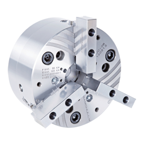
SAMCHULLY SH User manual

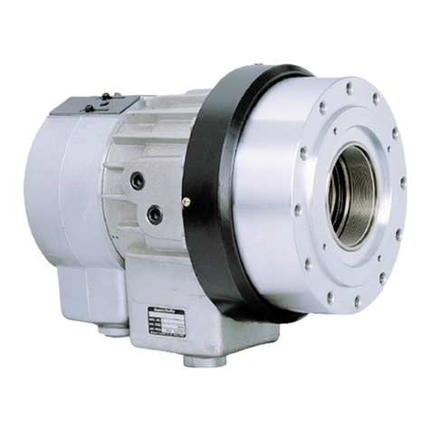
Mega-Bore Short-body
Open-Center Hydraulic Cylinder
Instruction Manual
SH
SHL 대관통경 박형
중공 유압실린더
취급설명서
标准开心式油缸
说明书
실린더를 조작하기 전에 이 설명서의
위험/경고 항목을 잘 읽고 숙지해
주십시오.
이 설명서를 궁금한 사항이나 점검할 사
항 등 필요할 때 참조할 수 있도록 잘
보관하십시오.
IMPORTANT 重要
중요
请仔细阅读并了解危险/警告 本评估
手册项目営业前 气缸。
请妥善保存本手册的答案在你身边的
任何问题,你可能并检查。
Please read and understand DANGER/
WARNING items in this maunal before
operating the cylinder.
Please keep this manual by your side
for answers to any questions you may
have and to check.


경고 용어
안전하게 사용하기 위해서 필요한 경고
사항을 본서에 기재했으니, 반드시 읽어
주십시오. 문장 중의 마크는 특히
주의하여 주십시오. 산업용 기계이므로
사용자 또는 이 장비를 사용하는 다른 사
람에게 위험할 수 있는 항목이나 조작에
는 “안전 경고 기호” 를 사용하여 사용
자의 주의를 환기시킵니다. 안전 경고 기
호로 표시한 지침을 잘 읽고 반드시 준수
해 주십시오.
안전 경고 기호
삼천리기계의 제품을 사용해 주셔서 진
심으로 감사 드립니다. 본 취급설명서에
따라 제품의 사용방법을 바르게 이해하
시고, 귀사의 생산에 기여할 수 있도록
활용하여 주십시오.
또한, 알아두면 편리한 제품의 성능 등에
관하여 유의사항으로 설명해 두었습니
다. 본 취급설명서는 분실되지 않도록 항
상 제품 가까이에 보관하여 주십시오.
!
!DANGER
위 험
적절한 안전 절차와 지침을 준수하지 않
으면 사망에 이르거나 중상을 입게 되는
매우 위험한 상황을 나타냅니다.
!
WARNING
경 고
적절한 안전 절차와 지침을 준수하지 않
으면 사망에 이르거나 중상을 입을 수
있는 잠재적으로 위험한 상황을 나타
냅니다.
!CAUTION
주 의
적절한 안전 절차와 지침을 준수하지 않
으면 가벼운 상처나 부상을 입을 가능성
이 있는 잠재적으로 위험한 상황을 나
타냅니다.
IMPORTANT
유의사항
제품의 성능 및 오류나 실수를 막기 위
한 지침입니다.
Precautions 前言
머리말
警告事项
!DANGER
危 险
!
WARNING
警 告
!CAUTION
注 意
IMPORTANT
重 要
具有跟重大的事故和死亡差不多的
危险。
可能引起轻微的负伤或产品受损。
容易疏失的事项以及应该熟悉的产
品性能。
真诚感谢您购买我们三千里公司的
液压卡盘。
请正确地理解本液压卡盘的操作说明
书中明示的使用方法,以便提高贵司
的生产能力。
警告标志
为了用户的安全,本说明书记载了必
要的“警告事项”,请您务必阅览。
说明书中标明要 特别注意。关于液
压卡盘的性能等,我们用”留意事
项”进行了说明。
可能引起重大事故和死亡的危险。
Thank you so much for choosing
Samchully. Please read this manual
carefully and fully understand the
procedures for installation, operation,
inspection and maintenance before
operating the product.
Keep this manual handy as it contains
detailed information on product
functionality.
To ensure safe operation, please read
this instruction manual and pay partic-
ular attention to the symbol which
emphasizes important information.
Warning symbol
Warning term
!DANGER
!
WARNING
!CAUTION
IMPORTANT
Indicates an imminently hazardous
situation which, if not avoided, will
result in death or serious injury. These
warning messages include the preven-
tive actions that are indispensable to
avoiding danger.
Indicates a potentially hazardous
situation which, if not avoided, will
result in death or serious injury. These
warning messages include the preven-
tive actions that are indispensable to
avoiding danger.
Indicates a potentially hazardous
situation which, if not avoided, could
result in minor injury or machine
damage.
Instructions for optimal performance
and avoiding errors or mistakes.
!

4Rotary Cylinder
목 차
1. 사용 및 안전을 위하여 .....................................................7
2. 개 요 .................................................................10
2-1 모델형식 표기 .................................................................10
2-2 구조 작동 ....................................................................10
3. 설 치 .................................................................12
3-1 실린더 아답터의 제작, 설치 .......................................................12
3-2 드로우 파이프 제작, 설치 .........................................................14
3-3 실린더의 설치 .................................................................16
3-4 실린더 체결볼트의 체결토크 .......................................................19
3-5 드레인 포트 ...................................................................20
3-6 유압회로 설계에 대하여 ..........................................................21
3-7 방향 전환밸브 유압 유니트의 설치 및 배관 .............................................23
3-8 작동유 .......................................................................24
3-9 시운전 .......................................................................25
3-10 안전밸브 ....................................................................27
4. 보수점검 ..............................................................28
5. 고장 및 대책 ...........................................................29
6. 사 양 .................................................................31
8. 부품도 ................................................................34
9. 쿨런트 콜렉터 ..........................................................38
9-1 개 요 ........................................................................38
9-2 근접 스위치의 사양 .............................................................39
9-3 설 치 ........................................................................40
9-4 쿨런트 콜렉터 부품 목록 ..........................................................41

5
Instruction Manual
Table of contents
1. Operation for safety .....................................................7
2. Summary .............................................................10
2-1 Model coding .................................................................10
2-2 Construction and operation .......................................................10
3. Mounting .............................................................12
3-1 Manufacturing and installation of cylinder adaptor ......................................12
3-2 Manufacturing and installation of draw pipe ...........................................14
3-3 Cylinder mounting ..............................................................16
3-4 Torque spec for cylinder mounting bolts .............................................19
3-5 Drain port ....................................................................20
3-6 Oil Pressure circuit diagram .......................................................21
3-7 Setting up the control valve, hydraulic unit and piping ...................................23
3-8 Hydraulic oil ..................................................................24
3-9 Trial operation .................................................................25
3-10 Safety valve .................................................................27
4. Maintenance ..........................................................28
5. Troubleshooting .......................................................29
6. Specification .........................................................31
8. Parts list .............................................................34
9. Coolant collector ......................................................38
9-1 Summary ....................................................................38
9-2 Proximity switch specification .....................................................39
9-3 Mounting ....................................................................40
9-4 Coolant collector parts list ........................................................41

6Rotary Cylinder
目录
1. 安全守则 ..................................7
2. 概要 ................................... 10
2-1卡盘形式标明 ................................... 10
2-2 構造與操作 .................................... 10
3. 安装 ................................... 12
3-1 制造及 安装气缸适配器 .............................. 12
3-2 拉管的制作与安装 ................................. 14
3-3 油缸的装配 .................................... 16
3-4 气缸持紧螺检的符紧扭矩 .............................. 19
3-5 泄油口 ...................................... 20
3-6 关于液压电路的设计 ................................ 21
3-7 方向转换阔、液压组件的安装和配管的使用 ...................... 23
3-8 启动油 ...................................... 24
3-9 试运行 ...................................... 25
3-10 安全阀 ..................................... 27
4. 维修 ................................... 28
5. 故障和对策 ................................ 29
6. 技术参数 ................................. 31
8. 配件表 .................................. 34
9. 冷却集电极 ................................ 38
9-1 总结 ....................................... 38
9-2 接近开关 技术参数 ................................ 39
9-3 安 装 ...................................... 40
9-4 冷却收集零件清单 ................................. 41

ON
OFF
NO!
7
Instruction Manual
사용 전에 알아두셔야 할 것, 지켜야 할
것을 정리해 놓았습니다. 반드시 읽어주
십시오. 당사는 이 취급설명서에 따르지
않은 경우에 발생하는 불량, 사고에 관한
책임은 지지 않습니다.
Please read this book before using
the chuck, and follow directions
given herein. We can not assume any
responsibility for any damage or ac-
cidents caused through things that is
not specified in this manual.
本守则记录了使用前应了解的事项,
请仔细阅读。
스핀들 회전 중에 전환밸브를 조작하시 마십시오.
실린더의 외부에 커버를 부착하십시오.
볼트체결시 지정된 토크로 체결하십시오.
Power switch off before setting,
inspecting, lubricating or changing the chuck.
Never operate selector valve and solenoid valve
during spindle rotation.
Provide the cover the periphery of cylinder.
Secure the mounting bolts.
检查、加油、更换、附着夹头时,应关闭电源。
夹头旋转时禁止操作转换阔。
钳固定螺栓。
신체의 일부나 의복이 말려들어가 부상당하는 위험이 있습니다.
회전 중에 조작하면 파악된 공작물이 이탈(비산) 될 위험이 있습니다.
신체의 일부나 의복이 말려들어가 부상당하는 위험이 있습니다.
실린더 재질이 알루미늄이므로, 평상시 체결토크 보다 작게 해야합니다.
Danger by catching operator in a machine.
Danger by discharge of clamped workpiece during spindle rotation.
Loose clothing or limbs may be caught in the machine.
Because the cylinder is made of aluminum, torque specification is slightly lower than normal.
由于汽缸是由铝,拧紧扭矩应比常规的转矩小。
若身体或衣服被缠进去是十分危险。
若旋转时操作, 夹持的加工产品具有被甩出去(飞散)的危险。
气缸应该盖上盖。
醒目的运营商在一台机器上的危险。
척의 설치, 보수점검, 윤활, 수리 시에는
반드시 설치기계의 전원을 끄십시오.
1. Operation for
safety
1. 安全守则
1. 사용 및 안전을
위하여
!DANGER
위 험 !DANGER !DANGER
危 险
수동전환 밸브
솔레노이드 밸브
선반
실린더 아답터
Manual selector valve
Solenoid valve
Lathe
Cylinder Adaptor
手动转换阀
电磁阀
车床
气缸适配器 볼트 크기
Bolt size
纖检直径
체결 토크
Tightening torque
拧紧力矩
N·m(kgf·cm)
M10 60 N·m(6.1kgf·cm)
M12 87 N·m(8.9kgf·cm)
M16 205 N·m(20.9kgf·cm)

MAX.
8Rotary Cylinder
드로우 파이프 체결시 확실하게 체결하십시오.
조작 실린더는 로크밸브, 릴리프밸브 내장형 사용시 루프
솔레노이드 밸브를 정전시에도 파악하는 회로로 하십시오.
사용 유압력은 실린더의 사양에 맞도록 조절하십시오.
Secure the draw tube.
In cases of power failure Samchully Cylinders are fitted with
check valves and pressure release valves. When power is
restored the solenoid valve resumes its normal function.
Set hydraulic pressure to chuck specification.
安全的平局管道。
操作气缸是在使用带锁阔门、泄放阔内装
型时请把电磁阔用于停电时夹持的电路。
设置液压夹头规范。
낙뢰, 정전시에 파악된 공작물의 이탈 (비산) 위험이 있습니다. 파악 위치를 맞게 설정하십시오.
Gripped workpiece may discharge by lighting or interruption. Set work to correct gripping position.
打雷、停电时夹持的加工产品有可能被用出去(飞散)的危险o 请妥善设定夹持位置。
피스톤 위치는 피스톤을 최대한 전진시킨 후 체결하십시오.
회전 중에 조작하면 파악된 공작물이 이탈(비산) 될 위험이 있습니다.
실린더가 파손되어 물려진 공작물이 이탈 (비산) 될 위험이 있습니다.
Install the cylinder with the piston in its forward position.
Danger by discharge of clamped workpiece during spindle rotation.
A damaged cylinder may cause the workpiece to fly out of the chuck.
推侧,活塞在行程结束设置。夹紧的工件在主轴旋转放电的危险。
具有油缸破损, 握持当中工件脱离 (飞散) 的重:大危险。
!
WARNING
경 고
!
WARNING
警 告
!
WARNING
Avoid impact damage.
请准确地加油。
충격에 절대 주의하십시오.
파손 또는 소착의 원인이 됩니다.
It will cause malfunction or seizing.
它会造成破损或扣押。
언클램프
실린더
클램프
Unclamp
Cylinder
Clamp
松开
气缸
夾持
솔레노이드 밸브
낙뢰, 정전
Solenoid valve
Lighting, Interruption
电磁阀
打雷, 停電
Pressure
Guage
0 6
1
2
3
4
5

ISO
VG32 or VG46
OIL
ON
OFF
OFF
9
Instruction Manual
실린더 탈부착시 리프팅 벨트를 사용하십시오.
전원을 끄고 지정된 작동유를 급유하십시오.
유압공급 라인에는 필터를 장착하십시오.
Whem mounting or unmounting the cylinder, use the lifting belt.
Turn off power source and use recommended hydraulic oil.
Incorporate a filter in pressure supply line.
拆卸和安装气缸时,请使用皮带。
在液压提供线上应安装过滤器。
부적합한 작동유를 사용하면, 작동속도가 느려지거나
추력이 떨어지기 때문에 가공물 비산의 위험이 있습니다.
Using the wrong kind of oil may cause loss of force which may
cause in the workpiece to be thrown from the chuck.
낙하시 위험하오니, 안전을 확인하십시오.
실린더내에 이물질이 혼입되면 소착의 원인이 되고,
작동이상으로 가공물 비산의 위험이 있습니다.
Improper lifting can lead to damage or injury.
Debris in the oil may result in pressure loss and cause the workpiece
to be thrown from the chuck.
下降的危险。检查安全。
应关闭电源后再添加启动油。
工作速度降低,推力变小,发生不完全握持, 有工件脱离(飞散)的危险。
如果在汽缸内混入异物, 会引起焦着现象,从而导致加工物的飞散。
!
WARNING
경 고
!
WARNING
警 告
!
WARNING
NO!
주류 또는 약물을 마시고 조작하는 것은 절대엄금하십시오.
Never attempt to operate a machine while
under the influence of alcohol or drugs.
판단력저하 또는 오조작의 위험이 있습니다.
Danger by operation fault and lowering judgement.
飲酒或服藥時嚴禁操作。
如在判斷力下降時操作將有操作失誤的危險。
주류, 약물
리프팅 벨트
오일필터
여과정도 : 20㎛ 이하
Alcohol, Drugs
Lifting belt
Oil filter
Filter accuracy : 20㎛ or less
酒精,药物
吊装带
机油滤清器
过滤程度 : 20㎛ 以下

10 Rotary Cylinder
중공형 유압실린더, SH 모델들의 형식
표기는 아래와 같습니다.
SH open-center hydraulic cylinder is
model coded as follows.
Oil from the hydraulic unit flows
through the ports of the cylinder and
retracts or extends the piston,
actuating the chuck. Circulated oil
runs through the sleeve body and
rotary valve, eventually returning to the
hydraulic unit through the drain line.
The lock valve prevents loss of pres-
sure in an event of a power outage,
maintaining grip force on the work-
piece. The relief valve prevents loss of
force in an event thermal expansion.
유압유닛으로부터 공급받는 작동유가
실린더내부의 유압회로를 거쳐 피스톤을
전진, 혹은 후진시켜 척에서 필요로 하는
파악력을 제공합니다.
유압포트로 공급된 유압은 슬리브와
회전밸브를 통하여 실린더 내부로 공급
되어 피스톤을 작동시킵니다.
순환된 유압은 반대편 유압포트를 통해
유압탱크로 복귀하는데 이를 내부 드레
인이라고합니다.
내부로 유입된 유압외에 회전체와 비회
전체의 조립틈새를 통해 베어링을 윤활
시키고 드레인 니플로 흘러 탱크로 복귀
하는데 이를 외부 드레인이라고 합니다.
로크밸브는 장비의 갑작스런 전원 off에
의하여 공작물이 비산하는 것을 방지하
기 위하여 유압공급이 중단되었을 때
실린더 내부의 유압이 손실되지 않고
일정시간동안 유지하는것이 주 목적입니
다. 릴리프 밸브는 일반적으로 감압밸브
라고 하며, 압축된 오일이 열팽창에 의하
여 극단적인 추력과 압력상승에 따른
실린더의 손상을 방지합니다.
SH开放中心液压缸型号编码如下。
由液压机组供应的液压油通过油缸内
部的 液压电路压缩活塞,从而提供
卡盘所需的夹持力。 传到液压端口
的液压,通过套管和旋转阀传到油缸
内部,从而运行活塞。经过循环的液
压通过反方向的液压端口进入液压站
的过程叫做‘内部排油’。 除
了流入到内部的液压以外,通过旋转
体和无旋体之间组装的空隙润滑轴承
之后,通过排油接头返回贮油箱的过
程叫做‘外部排油’。 检验阀的主
要功能是为了防止装备在突然停电的
情况下加工产品飞散,从而在液压供
应被中断时,使油缸内部的液压不受
损,让液压维持一定时间。 泄放阀
一般称之为减压阀,防止被压缩的油
热膨胀而产生极端性推力和压力上升
而损伤油缸。
SH
SHL
标准型
长行程型
Standard type
Long stroke type
: 표준형
: 롱스트로크형
SH 130 46
관통경 호칭 按通孔直径
Nominal Through Hole Diameter
실린더 내경 호칭 标称汽缸内径
Nominal inner diameter of cylinder
2. 概要
2. Summary2. 개 요
2-1 Model coding2-1 모델형식 표기
2-2 Construction and
operation
2-2 구조 작동
2-1卡盘形式标明
2-2 構造與操作
Never use this rotating cylinder with
a vertical lathe. This rotating cylinder
is not provided with an oil seal but
employs labyrinth sealing between the
sleeve body and the shaft so as to
minimize leakage that occurs during
high-speed rotation. For this reason,
when this rotating cylinder is mounted
on a vertical lathe, a large quantity of
oil will leak and the bearing will not be
sufficiently lubricated, resulting in dam-
age to the rotating cylinder.
이 회전실린더는 고속회전시의 누유를
최소화하기 위해 슬리브바디와 회전부
사이에 라비렌스 구조를 사용하고 있습
니다. 완전한 밀봉구조가 아니기때문에
실린더를 수직으로 사용하면 누유될뿐만
아니라 베어링의 윤활도 할 수 없어 고장
의 원인이 되므로 절대 수직으로 사용
하지 마십시오.
该液压油缸为了在高速旋转时做到漏
油的 最小化,在套管体和旋转部之
间采用了迷宫式结构。因为不是完整
的密封结构,若使油缸处于垂直状
态,不仅会发生漏油,还会因为没有
轴承的润滑作用而成为故障的原因,
因此请千万不要使油缸处于垂直
状态。
!CAUTION
주 의 !CAUTION
注 意
!CAUTION
11
Instruction Manual
Fig.1
슬리브 바디
슬리브
스토퍼
회전밸브
비회전체 회전체
릴리프 밸브
피스톤
실린더 바디
Sleeve Body
Sleeve
Stopper
Rotary Valve
Fixed ass’y Rotating ass’y
Relief Valve
Piston
Cylinder Body
袖长体
泰管
塞
旋转闽
无旋体 旋转体
泄压阀
活塞
缸体

0.005
0.005
E
C
A
B
D
12 Rotary Cylinder
Set the cylinder as close as possible
to the spindle support of the lathe. Re-
fer to Fig. 2 for proper mounting and
run-out measurement methods. Make
sure to fastening the set screw on the
adapter to prevent loosening.
실린더는 선반 스핀들 지지부에 가능
한한 접근시켜 주십시오.실린더 아답터
의 부착방법과 흔들림 측정방법을 Fig.2
에 표시하였습니다. 아답터의 풀림방지
용 세트 스크류를 필히 체결 하여 주십
시오.(Fig.3)
应使气缸靠近车床主轴的支撑部位。
气缸适配器的安装方法和摇动测量方
法如图。(Fig. 2)请务必梓紧适配器
的固定螺丝。(Fig. 3)
Fig.2
Fig.3
실린더 아답터의 흔들림 측정 / Run-out measurement of cylinder / 测量气缸适配器的摇动
3. Mounting 3. 安装
3. 설 치
3-1 Manufacturing and
installation of
cylinder adaptor
3-1 실린더 아답터의
제작, 설치
3-1 制造及 安装
气缸适配器
세트스크류(3~6개)
실린더 피스톤 로드 육각 구멍붙이 볼트 세트스크류
드로우 파이프
스핀들
실린더 아답터
체결나사
Set Screw(3~6EA)
Cylinder Piston Rod Hexagon Socket Head Bolt Set Screw
Draw Pipe
Spindle
Cylinder Adaptor
Fixing Screw
固定螺钉(3~6EA)
气缸 活塞杆 内六角圆柱头螺检 固定螺钉
绘制管
纺锤
气缸适配器
固定螺丝

13
Instruction Manual
형식 / Type / 型式 A(F7) B C D E(Max.)
후면체결 볼트
Rear Mounting Bolt
后安装螺栓
육각 구멍붙이 볼트
Hexagon Socket
Head Cap Screw
内六角 头内六角螺丝
SH-10036 100 48 115 5 12 -6-M10
SH-13046 100 65 130 5 15 6-M8 6-M10
SH-15052 130 70 170 5 22 6-M8 6-M10
SH-17068 160 85 190 5 25 6-M10 12-M10
SH-18077 160 95 190 5 25 6-M10 12-M10
SH-19082 160 100 190 5 25 6-M10 12-M12
SH-21010 200 125 225 5 30 6-M12 12-M12
SH-25011 230 140 275 6 46 6-M12 12-M16
SHL-17068 160 85 190 5 25 6-M10 12-M10
SHL-18077 160 95 190 5 25 6-M10 12-M10
SHL-25011 230 140 275 6 50 6-M12 12-M16
SHL-39024 320 265 420 6 51 -12-M16
Keep the run-out on cylinder adaptor
front face and the run-out on its
inside diameter both within 0.005mm.
Excessive run-out can cause vibration
and shorten the cylinder’s life span.
실린더 아답터의 전면 흔들림 및 기준경(
부착부)의 흔들림은 0.005mm 이하로 되
게 부착하여 주십시오. 흔들림이 클 경우
진동 및 흔들림 불량의 원인이 되고, 실
린더의 수명을 단축시킵니다.
安装时, 气缸适配器的前面摇动和
基准直径(安装部位)的摇动应为
0.005mm以下。若摇动程度过大,会
引 起震动,会缩短气缸寿命。
IMPORTANT
유의사항
IMPORTANT
重 要
IMPORTANT

L
c
d
b
a
A
B
L
d
14 Rotary Cylinder
The following Fig. 4 and 4-1 and table
indicate how to determine the length
of the draw pipe. Screw the draw pipe
into the piston rod with the piston
rod set.
Note) B : The following is cylinder
dimensions when chuck
jaws is fully opened.
드로우 파이프의 길이는 아래 규격에 따
라 주십시오. 피스톤 로드와 드로우 파이
프를 결합할때 피스톤 로드를 중앙에 위
치하게 하여 드로우파이프를 조립하십시
오.(Fig.4, 4-1)
주) B : 척 죠를 최대한 벌렸을 때의 치수
应按照如下方法决定拉管的长
度。(Fig.4) 在活塞杆部位插A拉管
螺丝时, 应尽量使活塞杆突出, 然后
再插入拉管。
注) B : 最大程度张开夹头爪时的
尺寸
3-2 Manufacturing and
installation of
draw pipe
3-2 드로우 파이프
제작, 설치
3-2 拉管的制作与安装
Fig.4
Fig.4-1
드로우 파이프 상세도 / Detail of draw pipe / 详细抽奖管
드로우 파이프 부착도 / Installing of draw pipe / 安装抽管
나사
Thread
线
실린더 피스톤 로드
드로우 파이프
척
척 아답터
실린더 아답터
Cylinder Piston Rod
Draw Pipe
Chuck
Chuck Adaptor
Cylinder Adaptor
气缸 活塞杆
绘制管
查
查适配器
气缸适配器

15
Instruction Manual
형식 / Type a b(f7) c dL비고 / Remarks
SH-10036 M42X1.5 38 25 12 A+B+10 HS-05 : L=A+26
SH-13046 M52X2.0 48 25 12 A+B+15 HS-06 : L=A+41
SH-15052 M60X2.0 55 30 12 A+B+8 HS-08 : L=A+39
SH-17068 M75X2.0 71 35 12 A+B+10 HS-10 : L=A+38.5
SH-18077 M85X2.0 80 35 12 A+B+10 HS-10 : L=A+38.5
SH-19082 M90X2.0 85 40 12 A+B+10 HS-12 : L=A+33
SH-21010 M112X2.0 106 45 12 A+B+5 HS-15 : L=A+33.5
SH-25011 M130X2.0 123 45 10 A+B-1 HS-15 : L=A+52
SHL-17068 M75X2.0 71 35 12 A+B HS-10 : L=A+38.5
SHL-18077 M85X2.0 80 35 12 A+B+10 HS-10 : L=A+38.5
SHL-25011 M130X2.0 123 45 10 A+B-1 HS-15 : L=A+52
SHL-39024 M250X3.0 243 45 17 A+B-5 MH-224 : L=A+35
The “L” dimension can be found by
the above table when the distance A
between the cylinder adaptor and the
chuck mounting face is given.(Fig.4-1)
ex) When the distance A (between
cylinder adaptor and back plate)
is 800mm in case of HS-06 and
SH-13046 the overall length of the
draw pipe will be as follows.
L=A+41= 800 + 41 = 841mm
● Accurate threading must be
provided on the draw pipe in
conformity.
표에서 L치수는 실린더 아답터와 척 아
답터 간의 거리 A가 정해지면 결정됩니
다. (Fig.4-1)
예) HS-06과 SH-13046에 실린더 아
답터, 척아답터 사이의 거리 A=800
일 경우, 드로우파이프의 전체 길
이는
L = A + 41 = 800 + 41 = 841mm
● a 나사는 피스톤 로드의 나사
에 맞도록 정확히 나사가공을
해 주십시오.
表中 L 尺寸可确定油缸 Adapter
与卡盘 Adapter 之间的距离
A。(Fig.4-1)
例)假定HS-06, SH-13046 组合成
A=800,拉制管的全长L是
L=A+41=800+41=841
● a部分螺丝加工,应对准油
缸 Pitch 螺丝部分正确加
工.(Fig.2)如果螺丝
接触松,会发生振动。
Make sure the draw pipe hardness is
adequate. Damage to draw pipe due
to insufficient hardness will risk the
workpiece being thrown from the
chuck.
드로우파이프는 충분한 강도를 갖도록
해주십시오. 강도부족시 파손되면 일순
간에 파악력이 떨어져 공작물 이탈(비산)
의 위험이 있습니다.
拉管应具有足够的强度. 若强度不
足。 则夹持力不足。夹头有可能被
用出去(飞敗)的危险。
!
WARNING
경 고
!
WARNING
警 告
!
WARNING
Loosening of threads during operation
can cause vibration and weaken the
draw pipe. Thread D, F should be
concentric whithin 0.05mm T.I.R.
나사의 체결이 풀어지면 진동 또는 강도
부족의 원인이 됩니다. D, F의 동심도는
0.05mm이하로 해주십시오.
若丝松开. 会产生震动或使强度下
降。a和e的同心度应小于0.05mm。
IMPORTANT
유의사항
IMPORTANT
重 要
IMPORTANT

b
c
e
f
A
a
d
B
16 Rotary Cylinder
드레인 포트는 수직 방향이 되도록 부착
하여 주십시오. 구조상 드레인 포트가 수
직방향이 안될 경우 슬리브 바디의 양단
에서 작동유가 넘쳐 누유가 발생합니다.
Mount the cylinder with the drain port
on the bottom. Otherwise, hydraulic
oil will overflow from both ends of
the sleeve body because of cylinder
structure.
安装时。应以垂直方向安装排油雄。
若排油端不垂直于下方。套管体两结
会发生漏油现象。
3-3 Cylinder mounting3-3 실린더의 설치 3-3 油缸的装配
In order to prevent the rotation of the
cylinder sleeve body, provide support
by utilizing the projections on the drain
port base.
After the support is mounted to the
lathe, retain the clearance between the
projected parts of the sleeve body and
the support so that the sleeve body is
not subjected to loading. (Fig.5)
When mounting the cylinder, mount
the support (anti-rotation bracket) to
the sleeve body. The run-out of the
periphery of the cylinder and of the
upper and lower movement of sleeve
body’s rear end must be less than
the standard values shown in table
of Fig.6.
실린더의 슬리브 바디가 회전하는 것을
방지하기 위해 드레인 포트의 돌출부를
이용하여 지지대를 설치하여 주십시오.
지지대는 선반에 부착 후, 슬리브 바디
에 힘이 가해지지 않도록 슬리브 바디
의 돌출부와 지지대 사이에 간격을 주십
시오. (Fig.5)
실린더 부착 시 흔들림은 슬리브 바디의
회전방지를 하도록 하고 스핀들을 회전
시켰을 때 실린더의 외주 흔들림을
그림6과 표에 표시한 규격치 이하로 부
착하여 주십시오.
为了防止气缸的套管体回转。应在排
油的 突出部位安装支架。
套管体的突出部位与支架之间应留下
间隔。以便在车床上安装支架时压不
蕃套管体 。(Fig.5)
就气缸安装时的摇动而言。为了防止
套管体旋转。使旋转主轴时气缸的外
围和套管体后端的上下摇动程度应在
图 6表示的规格值以下。
IMPORTANT
유의사항
IMPORTANT
重 要
IMPORTANT
Fig.5
실린더 부착 / Installing of cylinder / 安装气缸
실린더 아답터실린더슬리브 바디
선반
지지대
Cylinder AdaptorCylinderSleeve Body
Lathe
Support
气缸适配器气缸袖长体
车床
支持

A
0.005
B
17
Instruction Manual
형식 / Type / 型式 A B a bc d e f
SH-10036
선반에 의해서
결정됩니다.
To be determined
depending on the lathe.
待定
这取决于对车床。
75 4.5 ø47 50 30 1
SH-13046 75 4.5 ø47 50 30 1
SH-15052 75 6 ø47 50 30 1
SH-17068 80 6 ø47 50 30 1
SH-18077 80 6 ø47 50 30 1
SH-19082 80 6 ø47 50 30 1
SH-21010 80 6 ø47 50 30 1
SH-25011 80 6 ø47 50 30 1
SHL-17068 80 6 ø47 50 30 1
SHL-18077 80 6 ø47 50 30 1
SHL-25011 80 6 ø47 50 30 1
SHL-39024 80 6 ø47 50 30 1
In order to obtain the run-out shown
above, run-out on cylinder adap-
tor front face should be minimized.
(↗0.005 less)
상기 흔들림을 얻을 수 있도록 실린더
아답터전면의 흔들림을 되도록 작게하여
주십시오. (↗0.005 이내)
为了得到上述摇动值. 应置降尽低气
缸适配器前面的摇动。
(↗0.005 以下)
Fig.6
부착시의 흔들림 / Run-out cylinder after installation / 运行安装后缸
형식 / Type / 型式 A B
SH-10036 및 상당품 / SH-10036 equivalent / SH-10036 型及类似产晶 0.01 이내 / Less / 以下 0.015
SH-13046 및 상당품 / SH-13046 equivalent / SH-13046 型及类似产晶 0.01 이내 / Less / 以下 0.015
SH-15052 및 상당품 / SH-15052 equivalent / SH-15052 型及类似产晶 0.01 이내 / Less / 以下 0.015
SH-17068 및 상당품 / SH-17068 equivalent / SH-17068 型及类似产晶 0.01 이내 / Less / 以下 0.020
SH-18077 및 상당품 / SH-18077 equivalent / SH-18077 型及类似产晶 0.01 이내 / Less / 以下 0.020
SH-19082 및 상당품 / SH-19082 equivalent / SH-19082 型及类似产晶 0.01 이내 / Less / 以下 0.020
SH-21010 및 상당품 / SH-21010 equivalent / SH-21010 型及类似产晶 0.01 이내 / Less / 以下 0.020
SH-25011 및 상당품 / SH-25011 equivalent / SH-25011 型及类似产晶 0.01 이내 / Less / 以下 0.030
SHL-17068 및 상당품 / SHL-17068 equivalent / SHL-17068 型及类似产晶 0.01 이내 / Less / 以下 0.030
SHL-18077 및 상당품 / SHL-18077 equivalent / SHL-18077 型及类似产晶 0.01 이내 / Less / 以下 0.030
SHL-25011 및 상당품 / SHL-25011 equivalent / SHL-25011 型及类似产晶 0.01 이내 / Less / 以下 0.030
SHL-39024 및 상당품 / SHL-39024 equivalent / SHL-39024 型及类似产晶 0.01 이내 / Less / 以下 0.030

0.010
18 Rotary Cylinder
실린더 아답터를 실린더와 조립한 후 선
반에 부착 할 경우에는 아래 그림에 따
라 주십시오. V블록(쥬라콘 제품)에 다이
얼 게이지를 부착하여 실린더의 외경을
기준으로 실린더 아답터의 외경 중간위
치를 측정하여 동심도를 맞춰 주십시오.
(↗0.010 이내)
V블록의 기울어짐을 방지하기 위해 면접
촉기준으로 플레이트면에 설치합니다.
After mounting the adapter on the
cylinder, please follow the example as
shown below. Attach a tester such as
a JURACON gauge to a Vblock and
test the OD run-out on the cylinder
adaptor. (↗0.010 or less)
Make sure the gauge touches the
cylinder OD.
气缸适配器和气缸组装完成以后在车
床上 安装时。应按照下图进行。
SVblock(JURACON产品)安装百分
表。以气缸的外径为准。测置气缸
适配器外径的中间位。对好同心
度。(↗0.010 以下)
为了防止Vblock倾斜。以平面接为
准。安装在祖上。
실린더 아답터의 부착 气缸适配器的安装
Mounting of
cyliner adaptor
Fig.7

19
Instruction Manual
Fig.8
Thread engagement for cylinder
adaptor bolts should be as illustrated
below. (Fig.8)
※ Bolt engagement should be female
thread length on cylinder minus
2mm.
실린더를 실린더 아답터에 부착하는 경
우, 체결볼트의 나사결합 깊이는 아래그
림과 같이해주십시오. (Fig.8)
※ 볼트의 나사깊이는
(암나사 깊이 - 2mm)로 해주십시오.
在气缸适配器上安装气缸时。应按照
如下深度持拧紧检。(Fig.8)
※ 錄检的深度应为-2mm。(丝深度)
3-4 Torque spec for
cylinder mounting
bolts
3-4 실린더 체결볼트의
체결토크
3-4 气缸持紧螺检的符
紧扭矩
형식
Type
型式
볼트 직경
Bolt dia.
螺检直径
나사 깊이
Thread depth
螺纹深度
SH-10036 M10 17
SH-13046 M10 20
SH-15052 M10 20
SH-17068 M10 20
SH-18077 M10 20
SH-19082 M10 20
SH-21010 M12 20
SH-25011 M16 32
SHL-17068 M16 32
SHL-18077 M16 32
SHL-25011 M16 32
SHL-39024 M16 40
탭 깊이
볼트삽입깊이
부착 볼트
실린더 아답터
실린더
2
Tab Depth
Screwing Length
Mounting Bolt
Cylinder Adaptor
Cylinder
标签深度
旋合长度
安装螺栓
气缸适配器
气缸
Tighten the mounting bolt according
to the specified torque below.
※ Torque values are shown at 80% of
normal specifications due to the
aluminum composition of the
chuck.
부착볼트는 아래표의 규정 토크로 체결
하여 주십시오.
※ 실린더의 재질이 알류미늄이므로.
당사유압척에 규정하고 있는 볼트
직경에 대한 체결토크의 80%
입니다.
请按照如下规定的扭矩拧紧螺检。
※ 由于气缸材料为结制品。上述
扭矩是我公司液压夹头规定的丝
5径托紧扭矩的80%。
!
WARNING
경 고
!
WARNING
警 告
!
WARNING
볼트 크기 / Bolt size / 纖检直径 체결 토크 / Tightening torque / 拧紧力矩
[N·m(kgf·cm)]
M10 60 N·m(6.1kgf·cm)
M12 87 N·m(8.9kgf·cm)
M16 205 N·m(20.9kgf·cm)

20 Rotary Cylinder
실린더 드레인 회수시에는 자유낙하에
의한 드레인을 이용하기 때문에 드레인
포트가 경사지거나 기름의 흐름을 저해
하는 원인이 발생하면 슬리브 바디에서
작동유가 넘치게됩니다.
This rotating cylinder uses no oil seal
on its rotary section but utilizes gravity
for drainage. For this reason, if the
drain port is out of position or there
is any obstacle to the oil flow, oil will
overflow within the sleeve body.
此旋转气缸采用无油密封的旋转部
分,但利用重力排水回收。出于这个
原因,如果排水口位置,或油流有任
何障碍物时,油从壳体的溢出。
3-5 Drain port3-5 드레인 포트 3-5 泄油口
Use a wire-reinforced clear vinyl hose
for the drainage hose so that the oil
can be seen. Below are bad examples
of hose routing.
Drain port is not
positioned vertically.
The hydraulic circuit of another
actuator is connected to the drain line.
Return port and drain port
are connected.
The hose is sunk in the
tank of a hydraulic unit.
Other actuator
Drain hose is too
narrow.
The drain line is
choked.
A part of the hose is
higher than the distributor.
泄油口不 垂直放置。
另一种致动器的液压回路连接到所述
排水软管。
返回口和泄油口连接。 年底软管沉没在油箱液
压单元。
其他 执行器
排水管太窄。 泄油口 折磨。排水管被绞死分销商从
底线。
드레인 호스는 기름의 흐름상태를 볼 수
있는 와이어로 보강된 잘 꺽이지 않는 비
닐호스를 사용해 주십시오.(아래와 그림
과 같은 배관은 피해주십시오.)
드레인 포트가 수직으로
설치되지 않았다.
다른 유압기기의 회로가
드레인 호스에 결합되어 있다.
리턴포트와 드레인포트가
결합되어 있다.
드레인 호스의 끝단이
탱크안에 들어가 있다.
유압기구
드레인 호스가 너무
가늘다.
드레인 호스가
접혀 꺽여져 있다.
드레인 호스 일부가
드레인부 하단보다 높다.
使油中可以看出,使用的导线充满清
晰的乙烯软管排水软管。决不配置管
道,如下图所示。
!CAUTION
주 의 !CAUTION
注 意
!CAUTION
Fig.9
Fig.10
This manual suits for next models
13
Table of contents
Other SAMCHULLY Industrial Equipment manuals

SAMCHULLY
SAMCHULLY PAC User manual

SAMCHULLY
SAMCHULLY HCH User manual

SAMCHULLY
SAMCHULLY Multi Series User manual

SAMCHULLY
SAMCHULLY SYH User manual

SAMCHULLY
SAMCHULLY TS Series User manual

SAMCHULLY
SAMCHULLY SD User manual

SAMCHULLY
SAMCHULLY QJC User manual

SAMCHULLY
SAMCHULLY SD User manual

SAMCHULLY
SAMCHULLY MUT-600 User manual

SAMCHULLY
SAMCHULLY DY-125 Series User manual