JYE Tech 062 Quick start guide

DN062-18v03
JYE Tech - 1 - www.jyetech.com
Component locations (back side)
062 LCD Oscilloscope
AssemblyNotes
Applicable Models: 06203KP, 06204KP
Important Notes
1. Some components shown in the schematic and PCB layout are for options or adjustments.
Theydo not necessarily need to be installed. Components to be installed are listed in the part
list. Please ignore those components that appear in the schematic but notin the part list.
2. Users should payspecial attention to polarityand orientation for some components. These
components include diodes, transistors, electrolytic capacitors, ICs, connectors, etc. Incorrect
installation of such components mayresult in damage of parts and malfunction of the
instrument.
Check Contents
Users are encouraged to check contents against the Part List before installation. If any
missing/broken parts are found please report to your vender and JYE Tech
(support@jyetech.com) immediately. Your email should include following information:
1) Your name and contact method
2) Vender s name
3) Copyof receipt (or order confirmation) that indicates the contents and date of your
purchase.
4) List of missing/broken parts and quantity.
Note 1: Poweradapteris not included in the kits. Users need to preparea9 12 V
( >300mAcapacity) DC powersupply
Note 2: J6 (RCAjack) is included in the kit forjury-rig. Ifmoreprofessional feel
is wanted thereis aBNC Probe Kit (PN: 603-06201) available which
includes J1 (BNC connector).
Identify PCB:
Look at the back side (the side withmanyfootprints for surface mount devices). On its top-left
corner you should see the PCB part number.It should be “109-06200-00C”.If you see something
else then it will not match this instruction.

DN062-18v03
JYE Tech - 2 - www.jyetech.com
All SMD components soldered
SMD parts soldering
(To be completed)
[ Note: This sectiononly applies to kit 06203KP. Skip this section if the kit you purchased is 06204KP]
Through-hole Component Soldering
Please following these steps to do the assembly.
Step 1. Install diode D3
Diode is apolarized device. Before soldering make sure its cathode (the end with
white strip) goes into the hole with white bar as shown on PCB.
Step 2. Install electrolytic capacitors
Electrolytic capacitors are polarized devices. The electrolytic capacitors used inthe
kit are aluminum electrolytic capacitors. Usuallytheir longer leads (if have not been
cut before) denotepositive pole. The white stripon their bodydenotenegative pole.
The correct installation for these electrolytic capacitors is to put their positive pole
into the holes with square pad.
Step 3. Install inductorL2
This inductor is not apolarized device so youcan install it either way.Users are
reminded to handle thiscomponent with care and avoidbending its leads. This is
because the magnetic wires inside are rather thinand fragile. It is easyto get opened
if bended.
Step 4. Install headerJ4
J4 is the header for programming MCU ATmega64.
Step 5. Install connectorJ2
J2 is the DC power supplyinput connector.
Step 6. Install connectorJ6 (orJ1)
J6 (or J1 if BNC connector is chosen) is the connector for measurement signal input.
Step 7. Install test signal terminal J8
J8 is for test signal output. It is not areal connector.Use asmall piece of wire (the
leads cut offthe diode D7 are good for this) and make it aUshape. Solder it to the
upper two holes (the middle hole and the hole with square pad) and to the height of
about 0.3”.Then bend it outward to form a small ring.
Step 8. Install voltage regulatorU3 and its heat sink

DN062-18v03
JYE Tech - 3 - www.jyetech.com
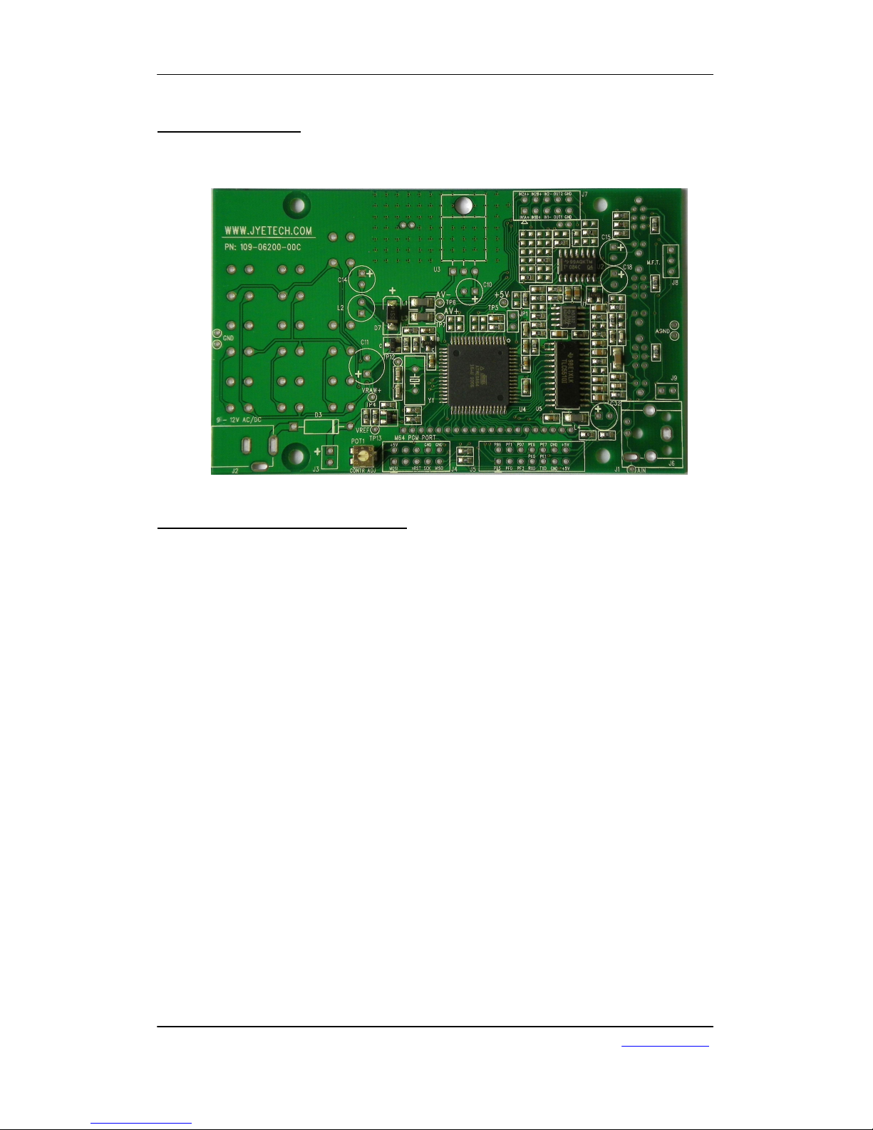
First mount heat sink (it is threaded) to PCB with provided M3 x10mm pan head
screw.Bend the leads of U3 properlyso that the leads go through the three soldering
holes and the hole at the tab fit the pan head screw.Tight U3 with the M3 nut firmly.
Solder its three leads at the other side.
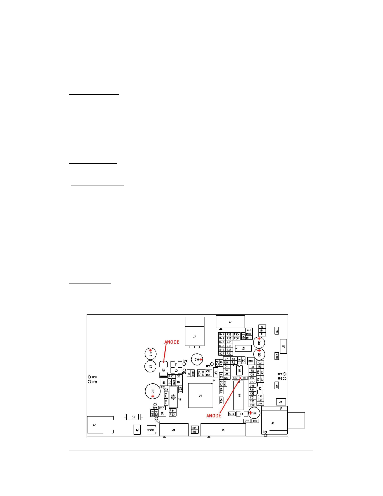
Step 9. Check +5Vpowersupply
Now we have finished all through-hole part installation on the component side
(oscilloscope back side). Before proceeding tothe rest installation we shouldpower
the board and check if there are anymajor errors. You need a9 –12VDC power
supply.Please note thatthe center conductor of its plug shouldbe positive. Plug it
into J2 and measure voltage at TP5 with amulti-meter.The multi-metershould +5V
+/- 0.2V.If it is far from this value something is wrong. Please check D3, C11, C10,
and U3 soldering.
If voltage at TP5 tested ok then continue.
Step 10. Connect JP1
JP1 serves as asafeguard. It separates power supplyfrom the rest circuits to avoid
abnormal power supplyburns everything. Now that power supply is tested good JP1
can be hard connected with apiece of wire. After connecting JP1 check voltage at
TP5 again. There shouldbe not much difference from itsprevious value. If you find
it changed significantly that indicates something is wrong with the restcircuits. You
need to find out the causes before proceeding.
If the voltage at TP5 staysat +5Vthen you can continue toinstall components at the
front side of board
Step 11. Install tact switches
It is important to installall tact switches upright and evenlysit on PCB. Otherwise
you will have trouble in putting up the front panel later. We stronglyrecommend that
for each switch onlysolder two across pins the first time. Then check and if you find
switch position is uneven adjust it bytouching the soldered legs with an iron while
push it by hand on the other side. After you satisfy yourself with that all switches are
located properlysolder all the rest legs.
You need tobe alittle cautious when soldering SW11and SW12 since two of the
legs are prettyclose to C11. Tryto avoid damaging the coat of C11.
Step 12. Install slide switches
Again you need to make sure the three slide switches are soldered upright and sit
evenlyto avoid troublein front panel installing. After inserting switch into PCB
solder onlytwo pins first. Then check and adjust until no uneven is seen. Solder all
the rest pins.
Step 13. Install LCD module
First solder the long SIPpins (the 20x pin strip) to LCD module. Look at the LCD
module. You will see same number holes at two sides. Look for the holes with labels.
These are where the long SIPpins should go. [Do not solderit on theside without
labels!] Insert the shorter ends of the long SIPpins intoLCD modulefrom the side
opposite to the glass and solder its two end pins first. By only soldering two end pins
it will allow you have chance tocheck and adjust. The SIPpins need tobe installed
perpendicular to the LCDboard. Otherwise it will not fit the main board. After you
are sure of perpendicularityis guaranteed you can solder all the rest pins.
After the long SIPpins have been done follow the same wayto install the two short
SIPpins (2x pin strips). These two SIPpins are to be installed at the opposite ends of
other side. These pins are for holding the LCDmodule to the main board onlyand
are not part of the circuit. Again, theymust be perpendicular to the LCD board so
that the LCD can fit into the main board.
Important Note: Cut all C10 and U3 leads flash to PCB to avoid short to LCD
module.
Now place the assembled LCD module into the main board. Solder the four corner
pins first. Check to make sure the LCD assembly is fully inserted into the main board.

DN062-18v03
JYE Tech - 4 - www.jyetech.com
All on-board components soldered (back side)
All on-board components soldered (front side)
If not touch the corner pins with iron while pushing the module firmlywith hand to
make it fullyin place. Solder all the rest pins after.
Verification
You can now verifyyour installation bypowering the unit the first time. Before doing so double
check your soldering. Check and make sure no leftovers (like cut-offpins) on PCB. Plug in power
supply.You should see the boot sequence that briefly displaysJYE Tech web address and
firmware part number and enters normal operation. If LCD backlight is on but nothing displayed it
couldbe the LCD contrast is not correct. You can change it by adjusting POT1 with asmall screw
driver.

DN062-18v03
JYE Tech - 5 - www.jyetech.com
Panel Installation
First install the four sets of standoffs. Then install back panel (its cut-out should align to the side
where power connector locates) with four screws. Place the caps on the push-buttons and install
the front panel with the rest screws. If you find some button don twork you mayneed to release
the screws a little bit.
Revision History
Version Date Summary
v01 2010.04.22 First created
v02 2010.07.09 Rewrote with more detailed instructions
V03 2011.02.14 Added anote under “Check Contents”section for BNC
connector J1.
Table of contents
Other JYE Tech Test Equipment manuals

JYE Tech
JYE Tech DSO112A User manual

JYE Tech
JYE Tech WAVE2 User manual

JYE Tech
JYE Tech DSO 068 User manual

JYE Tech
JYE Tech DSO 138 User manual

JYE Tech
JYE Tech DSO 096 Operating manual

JYE Tech
JYE Tech DSO 094 User manual

JYE Tech
JYE Tech DSO112A User manual

JYE Tech
JYE Tech DSO Shell 150 User manual

JYE Tech
JYE Tech DSO 138 User manual

JYE Tech
JYE Tech 062 Operating instructions