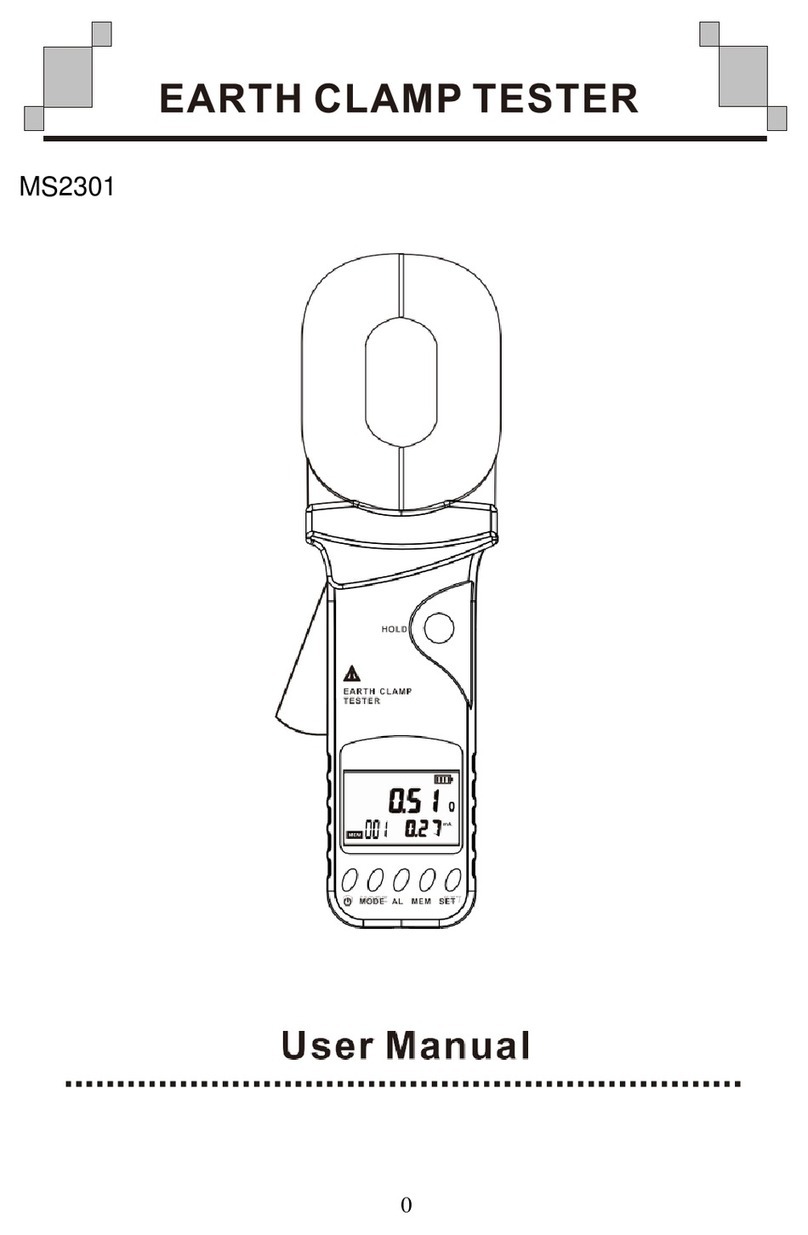
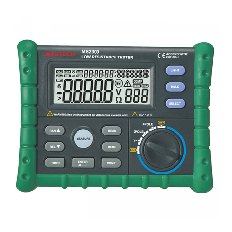
Mastech MS2302 User manual

MS2302
Digital Earth Resistance Tester
OPERATING INSTRUCTION

PRECISION MASTECH ENTERPRISES CO.
Unit 8, 21/FL, Yen Sheng Center, 64 Hoi Yuen Road, Kwun Tong, Kowloon, Hong Kong.
SHENZHEN HUAYI MASTECH CO., LTD.
East Wing, 8/F., Block 4, Saige Science and Technology Industrial Garden, Hua Qiang Bei Rd.
Shenzhen, China
DONGGUAN HUAYI MASTECH CO., LTD.
Yuliangwei Industrial Area, Qingxi Town, Dongguan, China
Tel: 0769 -87318225 Fax: 0769 – 87318228

Users’Guide for Earth Ground Resistance Tester
Contents
Contents
1. Safety………………………........................................................................................................…….1
2. Description.……………………...............................................................................................……....4
2.1 Meter Description…………………….......................................................................................……....4
2.2 Display…………………….....................................................................................................……....8
3. Specifications ……………………...........................................................................................……..10
3.1 Range and Precision…………...................................................................................………………..10
3.2 Measurement Method…………….................................................................................……………..10
3.3 Using Temperature and Humidity…………………….................................................................……..10
3.4 Storing Temperature and Humidity………………...............................................................…………..10
3.5 Battery……………....................................................................................................……………..11
3.6 Volume………………...................................................................................................……...........11
3.7 Weight…………….....................................................................................................………..........11

Users’Guide for Earth Ground Resistance Tester
Contents
3.8 Accessories…………….................................................................................................…………..……11
4. Operation Instructions……………............................................................................………….……12
4.1 Testing the Earth Voltage…………….............................................................................………….……12
4.2 Testing the Earth Resistance by the bi-electrode method………………...................................……….……12
4.3 Testing the Earth Resistance by the tri-electrode method………………...................................……………15
4.4 Data Storage ………..............................................................................................……………………17
4.5 Data Reading………….......................................……….......................................................…………18
4.6 REL Measurement….…………………......................................................................................…….…18
4.7 MAX/MIN/AVG Measurement……………....................................................................………...…..….19
4.8 Data Deletion………………............................................................................................….…...….….19
4.9 Back Light………………................................................................................................………….….19
4.10 Auto Off……………………....................................................................................................….…….19
5. Battery Replacement………………...............................................................................………….….20

Users’Guide for Earth Ground Resistance Tester
Safety
1. Safety
The earth resistance tester (hereinafter referred to as meter) , which is up to GB4793.1, the requirement on the safety
of electronic measurement instruments, is designed and manufactured in accordance with EN 61010-1, EN61010-2-030
Safety Standard, regarded as Grade 2 pollution, and the maximum voltage for the meter to probe can not exceed CAT
300V.
The users’ manual includes cautions and safety regulations, which specifies the rules in usage of the meter to avoid
personal injury accident and long keep the meter in good condition, therefore, please read the manual before using the
meter and adhere to the operation instructions inside it, and inobservance of the manual in using the meter may cause
personal injury or damage to the meter. Protection impairment if used in a manner not specified by the manufacturer.
Safety Symbols
Danger: improper operation will cause severe or fatal injuries.
Warning: improper operation may cause severe or fatal injuries
Caution:improper operation may cause personal injuries or damage to the meter
: Equipment protected throughout by double insulation or reinforced insulation
CAT III (measurement category III): Applicable to test and measuring circuits connected to the distribution part of the
building’s low-voltage MAINS installation.

-1-
Users’Guide for Earth Ground Resistance Tester
Safety
Danger
Check if the rotating switch is set to a proper position before measurement
Never use the meter in the vicinity of explosive gases, steam or dust.
Never connect wires or probes with wet hands or when the surface of the meter is humid.
Don’t touch the testing wires or probes in a measurement.
Don’t open the battery cover when the meter is working.
Warning
Never proceed a measurement under abnormalities, for example, the housing of the meter has been
damaged so that the metal of the meter or wires are naked.
Never replace the parts of the meter by yourself or modify it. Should the meter be damaged, return it to
the local dealers for examination or repair.
Don’t replace the batteries when the surface of the meter is humid.
Be sure to set the switch to “OFF” and disconnect the testing wires before replacing the batteries.

-2-
Users’Guide for Earth Ground Resistance Tester
Safety
Caution
Check if the total length of testing wires is inserted into the port before a measurement.
Take out of the batteries from the cartridge if the meter will not be used or will be stored for long.
Don’t expose the meter to sunlight, high temperature, humidity or dew
Clean the meter with neutral solvents or wet cloth instead of abrasives or organic solvents
Lay the meter in store only when it is dry.
Caution:
Using this appliance in an environment with a strong radiated radio-frequency electromagnetic field
(approximately 3V/m ),may influence its measuring accuracy. The measuring result can be strongly
deviating from the actual value.

-3-
Users’Guide for Earth Ground Resistance Tester
Description
2. Description
The meter is applicable to the testing of the earth resistance of the power supply wires, distribution wires inside a
room, electrical equipment or appliance, which can done in two measurement modes: Bi-poles or Tri-poles, and it also
can be used to measure the earth voltage.
Large digital LCD and backlights applied to the meter facilitate users to read the information on LCD. Besides, the
meter is capable of storing up to 100 groups of measurement data, which will not be lost even in case of power cuts so
that the user can easily consult the historical data. In addition, the meter can also be used to measure maximum,
minimum or average and measure relatively. Auto power-off function has been provided for it.
2.1 Meter Description
(1)Rotating Switch
It is used to selection between the measurement of earth voltage, measurement of resistance in Bi-pole method or
measurement of resistance in Tri-pole method.
(2)Key of ASP
It is used to start or cease auto power-off function.
(3)Key of LIGHT
It is used to turn on or turn off the backlight.
(4)Key of CLEAR
It is used to clear away data.

-4-
Users’Guide for Earth Ground Resistance Tester
Description
(5)LCD
It is used to display the data obtained and different symbols.

1
2
3
4
5
6
7
8
10
911 12 13
-5-
Users’Guide for Earth Ground Resistance Tester
Description

(6)Key of READ
It is used to read the data obtained.
(7)Key of MEMO
It is used to store the data obtained.
(8)Key of Measure
It is used to start or cease a measurement of resistance.
(9)Key of
It is used to select a memory for storage of data obtained.
-6-
Users’Guide for Earth Ground Resistance Tester
Description

(10)Key of MAX/MIN/AVG
It is used to switch between the measurement of maximum, minimum and average.
(11)Key of ENTER
It is used to confirm a storage or reading of data.
(12)REL
It is used to select relative measurement.
(13)Key of
It is used to select a memory for storage of data obtained.
(14)E socket
It is used to connect with the grounding pole.
(15)P/S socket
It is used to connect with the auxiliary grounding pole.
(16)C/H socket
It is used to connect with the auxiliary grounding pole.
-7-
Users’Guide for Earth Ground Resistance Tester

Description
2.2 LCD
(1)simulating bar
(2)Display of data obtained
(3)Displayofmemoryusedfordatastorage.
Descriptions of symbols on LCD:
TEST:a test is being progressed
>LIMIT:limit has been exceeded
-8-

Users’Guide for Earth Ground Resistance Tester
Description
MAX:Maximum
MIN:Minimum
AV G :Average
REL:Relative measurement
READ:Data reading
MEMO:Data is being put into a memory
USED:There are data in memories.
2POLE:Bi-pole method is being used for measurement of resistance.
3POLE:Ti-pole method is being used for measurement of resistance.
V:Volt(voltage)
KΩ:Ohm(resistance)
:Auto power-off has been started with the symbol on
:Battery is low with the symbol on
:For socket identification
:Alternating current
:For warnings and cautions
-9-

Users’Guide for Earth Ground Resistance Tester
Specifications
3. Specifications
Air temperature:23 5℃Relative humidity: <75%
3.1 Range Specifications
Range Precision
Earth Ground Resistance 10Ω±(1%rdg+3d)
4000Ω±(4% rdg +4d)
Earth Voltage AC50V(50/60HZ)±(2% rdg +4d)
3.2 Measurement method
Constant Current Conversion is used for the measurement of earth resistance, with the frequency of the testing current
about 800HZ and the size about 3mA.
Average rectification is used for the measurement of earth voltage.
3.3 Temperature and humidity for measurement
0~40℃,relative humidity under 85%
3.4 Temperature and humidity for keeping the meter
-10~50℃, relative humidity under 85%
-10-

Users’Guide for Earth Ground Resistance Tester
Specifications
3.5 Battery
Six 1.5V AA batteries
3.6 Volume
330 X 125 X 265
3.7 Weight
3.45kg
3.8Supplied accessories
3 test leads (one 15-meter-long red lead, one 10-meter-long green lead and one 5-meter-long black lead ) , 2auxiliary
earth bars
-11-

Users’Guide for Earth Ground Resistance Tester
Operation Instruction
4.Operation Instruction
Danger
In measurement of earth voltage, do not exert voltage above AC220V on the measurement port.
In measurement of earth resistance, there will occur potential of about 50 V between port E and S or between
ports E and C, therefore, protect yourself from electrical shock.
Before using the meter, check the electricity in the battery by turning on the meter, checking if there is “ ”on
display and replace the battery by following the steps described in Chapter “Replacement of the battery” if the symbol
exists.
4.1 Measurement of earth voltage
Rotate the switch to ~VE position, insert the end of meter cable into sockets E and S, with another end of meter
cable connected to either end of voltage source or resistance load in parallel way to measure . If there exists voltage, it
will be displayed on LCD.
4.2 How to measure earth resistance by Bi-pole method
Existing earth pole, such as buried metals (metal water pipe etc) , common earth of the commercial power supply or
lightning rods of high buildings, instead of auxiliary earth bars are used as auxiliary pole in this method.
-12-

Users’Guide for Earth Ground Resistance Tester
Operation Instructions
(1)Test Connection Diagram
CPE
EPP
RX re
-13-

Users’Guide for Earth Ground Resistance Tester
Operation Instructions
(2)Measurement of earth voltage.
Earth voltage measurement should be done before measurement of earth resistance to check the amount of earth
voltage, as voltage more than 10 V is likely to cause larger error in the measurement of earth resistance. In this case, cut
the measured object from the power supply and wait until the earth voltage drop for another measurement.
(3)Measurement of earth resistance
Rotate the switch to 2 POL position, press down the key of MEASURE to start the measurement, with the key
LED turned on and glittering. When the measurement comes to the end automatically, the buzzer will give a sound, the
key LED will go off and the data will be held automatically.
Attention: >LIMIT4000Ωdisplayed on LCD warns that the auxiliary earth resistance of the auxiliary earth
rods is so high that the current can not flow across the meter. Check if the test leads become loose and the amount
of the earth resistance of the auxiliary earth rods
(4)Value measu re d
Re, value of the earth resistance measured by Bi-pole method, equals the sum of re, the earth resistance of earth
rods, and RX, the real earth resistance of the object measured; therefore, RX=Re-re, meaning that the real resistance of
the object measured equals Re minus re.
-14-

Users’Guide for Earth Ground Resistance Tester
Operation Instructions
4.3 Measurement of the resistance by Tri-pole method
Potential Drop Method is used by the meter for the measurement of the earth resistance. Particularly, RX, the earth
resistance is figured out by first allowing I, the rated current, to flow between E, the object measured (the earth rods) and
C, the current pole, then measuring V, the potential difference between E and P, the voltage pole.
(1)Connect the test leads to the meter as follows
CPE
EPC
5 10m 5 10m
-15-
Table of contents
Other Mastech Test Equipment manuals

Mastech
Mastech Analog Earth Resistance Tester User manual

Mastech
Mastech MS7222 User manual

Mastech
Mastech MS8910 User manual

Mastech
Mastech MS8910 User manual

Mastech
Mastech KPS-TL300 User manual

Mastech
Mastech MS5215 User manual

Mastech
Mastech MS6810 User manual

Mastech
Mastech MS2309 User manual

Mastech
Mastech MS5910 User manual

Mastech
Mastech ms5908 User manual