MVA004 User manual and device specification
August 2017 Page 4 of 23 1DSMVA004_0817v11e
3 System description
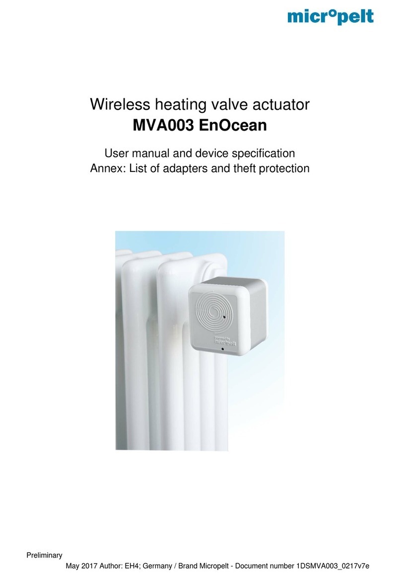
This document defines the properties of Micropelt’s battery free thermostatic radiator valve MVA004. The unit
is directly mounted onto radiator valve bodies (M30x1,5 thread), where it controls the room temperature, based
on signals of a central controller. It is radio-controlled and powered by energy harvesting, so it neither requires
any cabling work nor does it consume batteries. It is designed for maintenance-free operation. The wireless
design makes the unit ideal for retrofit installation and cost-sensitive projects, where cabling cost is prohibitive.
At its heart, the MVA004 contains a thermoelectric harvesting module and integral energy storage. Beyond
this, it contains an electromechanical valve actuator, a radio module and a microcontroller that makes all parts
of the system work together. The actuator is equipped with a number of hard- and software functions that not
only allow remote-management (ReMan) and -commissioning (ReCom) but also features unique status and
monitoring capabilities. The device also offers a debug- and deployment-friendly radio communication interval
of 10 seconds for the first 10 minutes following its initial activation.
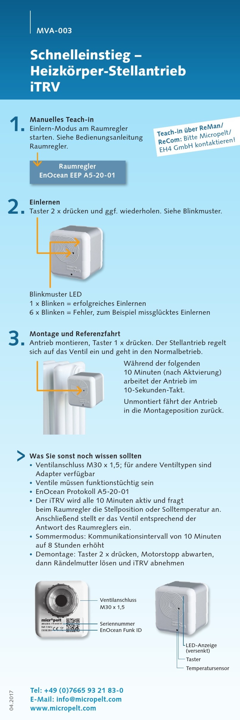
At its user interface, MVA004 has a red and a green LED, which are described in more detail in section 4. Two
internal temperature sensors are used with a) its internal temperature controller and freeze protection control
(ambient sensor) and b) the automatic radio duty cycle control of 2, 5 or 10 minutes (flow temperature sensor).
MVA004 is operating with EnOcean standard EEP A5-20-01 (4BS) in either valve position or set
temperature mode. According to the standard protocol, the drive reports to the room controller every 2/5 or 10
minutes (auto radio interval based on flow temperature) and transmits the value of its valve position. The room
controller responds with either a new control value in the value range 0% (valve closed) to 100% (valve
maximum open) or setpoint temperature (0 ... 40 ° C). When the setpoint changes, the actuator motor moves
the motor to the new position.
When operating with the setpoint temperature, it is recommended to use a separate, external room
temperature sensor, which transmits the room temperature to the room controller, which then transmits it to
the drive (as described in A5-20-01 protocol). Without external room temperature, the internal controller uses
the sensor installed in the drive (picture page 5). By heat input from the radiator in the drive, there are
deviations between the measured and actual room temperature, which are compensated by means of an
integrated correction function.
The actuator is in the delivery state in mounting position (motor positon is fully retracted). The actuator has
valve recognition. Unmounted but activated will automatically move the motor back to mounting position and
switch-off the actuator.
The internal energy storage of the actuator is fully charged upon delivery, so that sufficient energy is
available for installation and up to approximately one year of operation. The drive works 365 days a year.
When the heating system is switched on, the actuator then supplies itself independently via the heat of the
heating circuit. Due to the surplus of generated energy in winter, the internal storage provides sufficient energy
for the year-round operation including transition periods and summer.
In the event of a radio failure (6 unsuccessful communication attempts), the internal temperature controller
is activated and the radiator is regulated to a preset 21 ° C. A change of the radio interval does not take place.
The drive goes into normal operation as soon as the radio communication is restored.
When operating in unheated rooms, the internal memory will eventually be discharged. The drive then
moves to the 50% position to recharge the memory. Operation of the drive in unheated rooms is not
recommended
