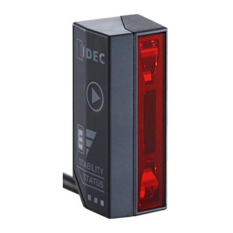
Microscan Quadrus Verifier User manual

Quadrus Verifier
User's Manual
P/N 83-006702 Rev C

ii Quadrus Verifier User’s Manual
Copyright and Disclaimer
Copyright © 2007
by Microscan Systems, Inc.,
1201 S.W. 7th Street, Renton, Washington, U.S.A. 98057
(425) 226-5700 FAX: (425) 226-8682
ISO 9001:2000 Certification No. 06-1080
Issued by TüV USA
All rights reserved. The information contained herein is proprietary and is provided solely for the purpose
of allowing customers to operate and/or service Microscan manufactured equipment and is not to be
released, reproduced, or used for any other purpose without written permission of Microscan.
Throughout this manual, trademarked names might be used. Rather than put a trademark (™) symbol in
every occurrence of a trademarked name, we state herein that we are using the names only in an editorial
fashion, and to the benefit of the trademark owner, with no intention of infringement.
Disclaimer
The information and specifications described in this manual are subject to change without notice.
Latest Manual Version
For the latest version of this manual, see the Download page on our web site at www.microscan.com.
Microscan Systems, Inc.
1201 S.W. 7th Street
Renton, WA 98057
U.S.A.
Tel: 425 226 5700
Fax: 425 226 8250
Microscan Europe
Tel: 31 172 423360
Fax: 31 172 423366
Microscan Asia Pacific R.O.
Tel: 65 6846 1214
Fax: 65 6846 4641

Quadrus Verifier User’s Manual iii
Introduction
Microscan Limited Warranty Statement and Exclusions
What Is Covered?
Microscan Systems Inc. warrants to the original purchaser that products manufactured by it will be free
from defects in material and workmanship under normal use and service for a period of one year from the
date of shipment. This warranty is specifically limited to, at Microscan’s sole option, repair or replacement
with a functionally equivalent unit and return without charge for service or return freight.
What Is Excluded?
This limited warranty specifically excludes the following: (1) Any products or parts that have been subject
to misuse, neglect, accident, unauthorized repair, improper installation, or abnormal conditions or opera-
tions; (2) Any products or parts that have been transferred by the original purchaser; (3) Customer mis-
adjustment of settings contrary to the procedure described in the Microscan Systems Inc. owners manual;
(4) Upgrading software versions at customer request unless required to meet specifications in effect at the
time of purchase; (5) Units returned and found to have no failure will be excluded; (6) Claims for damage
in transit are to be directed to the freight carrier upon receipt. Any use of the product is at purchaser’s own
risk. This limited warranty is the only warranty provided by Microscan Systems Inc. regarding the product.
Except for the limited warranty above, the product is provided “as is.” To the maximum extent permitted by
law, this express warranty excludes all other warranties, express or implied, including but not limited to,
implied warranties of merchantability and. Technical support questions may be directed to: help-
particular purpose. Microscan Systems Inc. does not warrant that the functions contained in the product
will meet any requirements or needs purchaser may have, or that the product will operate error free, or in
an uninterrupted fashion, or that any defects or errors in the product will be corrected, or that the product
is compatible with any particular machinery.
Limitation of Liability
In no event shall Microscan Systems Inc. be liable to you or any third party for any special, incidental, or
consequential damages (including, without limitation, indirect, special, punitive, or exemplary damages for
loss of business, loss of profits, business interruption,or loss of business information), whether in contract,
tort, or otherwise, even if Microscan Systems Inc. has been advised of the possibility of such damages.
Microscan Systems Inc.’s aggregate liability with respect to its obligations under this warranty or otherwise
with respect to the product and documentation or otherwise shall not exceed the amount paid by you for
the product and documentation. Some jurisdictions do not allow the exclusion or limitation of incidental or
consequential damages or limitations on an implied warranty, so the above limitation or exclusion may not
apply to you. This warranty gives you specific legal rights, and you may also have other rights which may
vary from state to state.
Tel: 425.226.5700 | Fax: 425.226.8250 | helpdesk@microscan.com

iv Quadrus Verifier User’s Manual
Table of Contents
Table of Contents
Chapter 1 Quick Start
Step 1 Check Required Hardware...........................................................1-2
Step 2 Connect the System.....................................................................1-3
Step 3 Install ESP ...................................................................................1-4
Step 4 Select Model................................................................................1-5
Step 5 Select Communications Protocol.................................................1-6
Step 6 Position Verifier and Symbol........................................................1-7
Step 7 Locate Symbol............................................................................ 1-8
Step 8 Calibrate Reflectance...................................................................1-9
Step 9 Set Verification Parameters ..................................................... 1-10
Step 10 Verify Symbol ......................................................................... 1-11
Step 11 Generate and Save Verification Report ................................. 1-14
Chapter 2 Using ESP
Verification...............................................................................................2-2
Application Mode.....................................................................................2-3
Menu Toolbar ..........................................................................................2-4
View...................................................................................................... 2-11
Navigating in ESP .................................................................................2-12
Send/Receive Options...........................................................................2-13
Chapter 3 Verification
Verification Serial Commands.................................................................3-2
Verification Operational Commands........................................................3-2
Overview of Verification...........................................................................3-3
ISO/IEC 15415 Evaluation Parameters...................................................3-5
AS9132 Evaluation Parameters ..............................................................3-7
AIM DPM Evaluation Parameters..........................................................3-10
General Verification Serial Output.........................................................3-12
General Verification Output by ESP......................................................3-17
ISO/IEC 15415 Verification Setup.........................................................3-19
ISO/IEC 15415 Verification Setup by ESP............................................3-21
ISO/IEC 15415 Serial Output ................................................................3-23
ISO/IEC 15415 Output by ESP .............................................................3-33
AIM DPM Verification Setup..................................................................3-40
AIM DPM Verification Setup by ESP.....................................................3-42
ISO/IEC 15415 Verification by Serial Command...................................3-44
AS9132/JES 131 Marking Method........................................................3-49
AS9132/JES 131 Marking Method by ESP...........................................3-51
AS9132 Serial Output............................................................................3-53
AS9132 Output by ESP.........................................................................3-62
AS9132 Verification by Serial Command ..............................................3-67
AIM DPM Verification by Serial Command............................................3-68
Verification by ESP................................................................................3-70

Quadrus Verifier User’s Manual v
Introduction
Chapter 4 Unique Item Identifiers
Overview of IUID and UII.........................................................................4-2
Non-UII Characters..................................................................................4-3
UII Mode Features...................................................................................4-4
Error Messaging ......................................................................................4-6
Valid Data Qualifier Formats ...................................................................4-8
UII Parsing...............................................................................................4-9
Chapter 5 Communications
Communications by ESP.........................................................................5-2
Communications Serial Commands ........................................................5-3
RS-232/422 Host Port .............................................................................5-4
RS-232 Auxiliary Port ..............................................................................5-9
Network .................................................................................................5-18
Preamble...............................................................................................5-21
Postamble..............................................................................................5-22
Response Timeout ................................................................................5-23
LRC Status............................................................................................5-24
Aux Port System Data Status................................................................5-25
Chapter 6 Read Cycle
Read Cycle by ESP.................................................................................6-2
Read Cycle Serial Commands ................................................................6-3
Read Cycle Setup....................................................................................6-4
Multisymbol..............................................................................................6-5
Trigger .....................................................................................................6-7
Serial Trigger.........................................................................................6-13
End of Read Cycle.................................................................................6-15
Active Camera.......................................................................................6-17
Capture Mode........................................................................................6-18
Capture Timing......................................................................................6-23
Dual Camera Switching.........................................................................6-25
Store No Read Image............................................................................6-30
Setting Up the Verifier for EZ Trax ........................................................6-31
Chapter 7 Symbologies
Symbologies by ESP...............................................................................7-2
Symbologies Serial Commands ..............................................................7-3
Data Matrix..............................................................................................7-4
QR Code..................................................................................................7-6
Code 39...................................................................................................7-7
Code 128...............................................................................................7-10
BC412....................................................................................................7-11
Interleaved 2 of 5...................................................................................7-13
UPC/EAN...............................................................................................7-16
Pharmacode..........................................................................................7-19
RSS Expanded .....................................................................................7-21

vi Quadrus Verifier User’s Manual
Table of Contents
RSS Limited ..........................................................................................7-22
RSS-14..................................................................................................7-23
PDF417 ................................................................................................. 7-24
MicroPDF417 ........................................................................................7-26
Composite .............................................................................................7-27
Narrow Margins.....................................................................................7-28
Symbology ID........................................................................................7-29
Background Color..................................................................................7-30
Chapter 8 I/O Parameters
I/O Parameters by ESP...........................................................................8-2
I/O Parameters Serial Commands ..........................................................8-3
Symbol Data Output................................................................................8-4
When to Output Symbol Data..................................................................8-6
No Read Message...................................................................................8-7
Bad/No Symbol Qualification...................................................................8-9
Read Duration Output ...........................................................................8-16
Output Indicators...................................................................................8-17
Serial Verification ..................................................................................8-20
Video Output .........................................................................................8-22
Image Output.........................................................................................8-24
Image Captioning..................................................................................8-26
Synchronous Trigger.............................................................................8-28
EZ Button ..............................................................................................8-30
EZ Button Modes...................................................................................8-32
Input 1 ...................................................................................................8-34
Output 1 Parameters.............................................................................8-35
Output 2 Parameters.............................................................................8-48
Output 3 Parameters.............................................................................8-52
Configuring EZ Trax Output ..................................................................8-56
Chapter 9 Matchcode
Matchcode by ESP..................................................................................9-2
Matchcode Serial Commands .................................................................9-3
Overview of Matchcode...........................................................................9-4
Matchcode Type......................................................................................9-5
Sequential Matching................................................................................9-6
Match Start Position................................................................................9-7
Match Length...........................................................................................9-8
Wild Card Character................................................................................9-9
Sequence On No Read.........................................................................9-10
Sequence On Mismatch........................................................................9-11
Sequence Step......................................................................................9-12
Match Replace ...................................................................................... 9-13
Mismatch Replace.................................................................................9-14
New Master Pin.....................................................................................9-15

Quadrus Verifier User’s Manual vii
Introduction
Chapter 10 Diagnostics
Diagnostics by ESP...............................................................................10-2
Diagnostics Serial Commands ..............................................................10-2
Counts (Read Only)...............................................................................10-3
External Camera Message....................................................................10-4
Over Temperature Message..................................................................10-6
Service Message...................................................................................10-7
Chapter 11 Camera Setup
Camera Setup by ESP ..........................................................................11-2
Camera Setup Serial Commands..........................................................11-3
Video .....................................................................................................11-4
Evaluation..............................................................................................11-6
Region of Interest (ROI) ......................................................................11-10
IP Database.........................................................................................11-13
Dynamic Setup ....................................................................................11-14
Camera................................................................................................11-16
Illumination Source..............................................................................11-17
Thresholding........................................................................................11-18
Image Processing Settings..................................................................11-19
Hollow Mode........................................................................................11-21
Mirrored Image ....................................................................................11-22
Chapter 12 IP Database
IP Database by ESP..............................................................................12-2
IP Database Serial Commands .............................................................12-3
Overview of IP Database.......................................................................12-4
IP Database Window in ESP.................................................................12-6
Number of Active Database Settings.....................................................12-7
Image Processing Database .................................................................12-8
Image Processing Database by ESP. .................................................12-10
Save Current Settings to Database.....................................................12-11
Load Current Settings from Database.................................................12-12
Request Selected Database Settings..................................................12-13
Request All Database Settings............................................................12-13
Chapter 13 Terminal
Terminal Window...................................................................................13-2
Find .......................................................................................................13-3
Send......................................................................................................13-4
Macros...................................................................................................13-5
Terminal Window Menus.......................................................................13-6
Chapter 14 Utilities
Serial Utility Commands ........................................................................14-2
Read Rate .............................................................................................14-3
Counters................................................................................................14-4

viii Quadrus Verifier User’s Manual
Table of Contents
Device Control.......................................................................................14-6
Differences from Default........................................................................14-7
Master Database...................................................................................14-8
Firmware .............................................................................................14-13
Bar Code Configuration.......................................................................14-16
Defaulting/Saving/Resetting................................................................14-17
Status Requests..................................................................................14-19
Other Operational Serial Commands ..................................................14-21
Chapter 15 Output Format
Output Format Serial Commands..........................................................15-2
Output Format Status............................................................................15-3
Format Assign .......................................................................................15-4
Format Extract.......................................................................................15-5
Format Insert.........................................................................................15-7
Output Filter Configuration .................................................................... 15-9
Ordered Output Filter ..........................................................................15-13
Chapter 16 Ethernet
Step 1 Setup..........................................................................................16-2
Step 2 Preliminary Steps.......................................................................16-3
Step 3 Communicating in Ethernet........................................................16-7
Step 4 Ethernet Application...................................................................16-8
Appendices
Appendix A General Specifications.........................................................A-2
Appendix B Electrical Specifications.......................................................A-4
Appendix C Connectivity Accessories.....................................................A-8
Appendix D Serial Configuration Commands........................................A-11
Appendix E ASCII Table........................................................................A-17
Appendix F Data Matrix Symbology......................................................A-19
Appendix G Object Detector..................................................................A-20
Appendix H Operational Tips ................................................................A-21
Appendix I Embedded Menus ...............................................................A-22
Appendix J Interface Standards ............................................................A-23
Appendix K Glossary of Terms..............................................................A-24
Index

Quadrus Verifier User’s Manual ix
Introduction
About the Quadrus Verifier
The key features of the Quadrus Verifier are:
• ISO/IEC 15415, AS9132, and AIM DPM verification options
• Self-contained, factory-calibrated optics and lighting for fast, easy integration into a
variety of manufacturing processes
• ISO/IEC 15426 certification for Data Matrix verification
•ESP Software for configuration and testing
About This Manual
This manual provides complete information on setting up, installing, and configuring the
Quadrus Verifier. The sections are presented in the order in which the Verifier might be set
up and made ready for industrial operation.
Note:
The terms
AS9132
and
AS9132
are used interchangeably throughout this documentation.
“AS9132” is the name of a specification, and the suffix “A” denotes the current published
version of the specification.
Highlighting
Serial commands and default settings are highlighted in rust bold. Cross-references
and web links are highlighted in blue bold. References to menu items are highlighted in
Bold Initial Caps.
Host Communications
There are four ways to configure and test the Quadrus Verifier:
1. Several configuration commands can be executed from the
EZ Button
without connection
to a host.
2. Microscan’s Windows-based ESP, the preferred method, which offers point-and-click
ease of use and visual responses to user adjustments.
3. Serial commands, such as <K100,1>, can be sent from a terminal program. They
can also be sent from a PLC or from ESP’s Terminal.
4. Embedded onboard menus are accessed from a terminal window with a <D> command.

xQuadrus Verifier User’s Manual
Statement of Agency Compliance
The Quadrus Verifier has been tested for compliance with CE (Conformité Européenne)
standards and guidelines and has been found to conform to applicable CE standards,
specifically the following requirements:
• ITE Disturbances: IEC 55022:1998 (radiated and conducted) Class A
• General Immunity: IEC 55024:1998 (residential)
• Heavy Industrial Immunity: IEC 61000-6-2:1999
• LED Radiation: IEC 60825-1

Quadrus Verifier User’s Manual xi
Introduction
Warning and Caution Summary
• Viewing the Quadrus Verifier’s LED output with optical instruments such as magnifiers,
eye loupes, or microscopes within a distance of 100 mm could cause serious eye injury.
• Maximum LED light output: 648 cd
• Wavelength: 464 nm; 518 nm; 635 nm
• Location of the Quadrus Verifier’s LED aperture window:
•CAUTION: Use of controls or adjustments or performance of procedures other than
those specified herein may result in hazardous radiation exposure.
WARNING
LED LIGHT
DO NOT VIEW DIRECTLY WITH OPTICAL INSTRUMENTS
CLASS 1M LED PRODUCT
Light Output: 648 cd Wavelength: 464 nm; 518 nm; 635 nm
IEC 60825-1:1993+A1:1997+A2:2001
LED Aperture Window

xii Quadrus Verifier User’s Manual
Warning and Caution Summary
Warning and Caution Summary (cont.)
• Max Power: 67 mW
• Wavelength: 660 nm
• Location of the Quadrus Verifier’s LED array:
•CAUTION: Use of controls or adjustments or performance of procedures other than
those specified herein may result in hazardous radiation exposure.
WARNING
LED RADIATION
DO NOT STARE INTO BEAM
CLASS 2 LED PRODUCT
Max Power: 67mW Wavelength: 660 nm
IEC 60825-1:1994+A1:2002+A2:2001
LED Array

Quadrus Verifier User’s Manual 1-1
1 Quick Start
Contents
This section is designed to get your Verifier up and running quickly so you can get a sense
of its capabilities and test sample symbols.
Detailed setup information for installing the Verifier in your application can be obtained in
the subsequent sections.
Step 1 Check Required Hardware................................................................................................ 1-2
Step 2 Connect the System.......................................................................................................... 1-3
Step 3 Install ESP......................................................................................................................... 1-4
Step 4 Select Model ..................................................................................................................... 1-5
Step 5 Select Communications Protocol...................................................................................... 1-6
Step 6 Position Verifier and Symbol.............................................................................................1-7
Step 7 Locate Symbol .................................................................................................................. 1-8
Step 8 Calibrate Reflectance....................................................................................................... 1-9
Step 9 Set Verification Parameters ........................................................................................... 1-10
Step 10 Verifiy Symbol.............................................................................................................. 1-11
Step 11 Generate and Save Verification Report ........................................................................ 1-14

1-2 Quadrus Verifier User’s Manual
Check Required Hardware
Step 1 — Check Required Hardware
Item Description Part Number
1Quadrus Verifier FIS-6700-100XG
2IB-150 Kit Included with Verifier
3Power Supply Included with Verifier
4Illumination Power Supply Included with Verifier
5Light Control Cable Included with Verifier
6Quadrus EZ Stand (not shown) Included with Verifier
7Monitor Kit 98-000096-01
8Object Detector 99-000017-01
Hardware Required
Caution: Be sure that all cables are connected BEFORE applying power
to the system. Always power down BEFORE disconnecting any cables.

Quadrus Verifier User’s Manual 1-3
Quick Start
Step 2 — Connect the System
Connecting to a Host by RS-232
1. Connect the Verifier to the IB-150 Kit.
2. Connect the IB-150 Kit host cable to the host.
3. Connect the Lighting Power Supply to the lighting chamber.
4. Connect the main power supply and cycle power to the Verifier.
Note: When wiring the IB-150 Kit to a host
with a 25-pin host connector, cross pins 2
and 3. When wiring the interface box to a
host with a 9-pin host connector, do NOT
cross pins 2 and 3.
Connecting to a Host by TCP/IP
See Chapter 16, Ethernet.
Hardware Configuration
Caution: Be sure that all cables are connected BEFORE applying power
to the system. Always power down BEFORE disconnecting any cables.
1
25
Side View of IB-150 showing Host
25-pin Socket Connection

1-4 Quadrus Verifier User’s Manual
Install ESP
Step 3 — Install ESP
Easy Setup Program (ESP) is Microscan’s proprietary setup and testing application. The
purpose of ESP is to provide a quick and easy way to set up and configure Microscan
products.
When the Quadrus Verifier is connected to a host computer (Windows Vista, XP, or 2000),
ESP can be used to set up communication with a host, configure various firmware settings,
and control verification processes.
If installing from a Microscan Tools CD:
1. Insert the Microscan Tools CD in your computer’s CD drive.
2. Choose ESP Software from the main menu.
3. Select the Current Version of ESP and follow the file download prompts.
If downloading from the web:
1. Go to http://www.microscan.com/downloadcenter
2. Create a new “myMicroscan” member account or, if you are already a member, enter
your user name and password.
3. Click the Download Software link and extract the latest version of ESP to a directory
of your choice. Note where your ESP.exe file is stored on your hard drive.
4. At the end of the installation process, the following icon will appear on your desktop:
5. Click the ESP icon to start the program.
System Requirements for ESP
• 166 MHz Pentium processor (recommended)
• Windows Vista, XP, or 2000 operating system
• Internet Explorer 5.0 or higher
• 64 MB minimum RAM
• 40 MB minimum disk space

Quadrus Verifier User’s Manual 1-5
Quick Start
Step 4 — Select Model
When you start ESP, the following menu will appear:
1. Click the button showing the Quadrus Verifier.
2. Click OK.
3. Note: You can also simply double-click the Quadrus Verifier button to make your
selection.
4. Click Yes when the following dialog box appears:
Note: If you need to select another model later, you can find it in Application Mode
under Model on the menu toolbar.

1-6 Quadrus Verifier User’s Manual
Select Communications Protocol
Step 5 — Select Communications Protocol
When the following dialog appears, make your selection and click Next.
RS-232
1. In the RS-232 dialog, if your communications port is not the default COM1, use the
dropdown menu to change your communications port.
2. Click Connect.
3. If the connection fails, click the Autoconnect button, select a different communications
port, and try again.
Note: If your host settings cannot be changed to match the Verifier’s settings, check the
Force Connect box.
TCP/IP
See Chapter 16, Ethernet.

Quadrus Verifier User’s Manual 1-7
Quick Start
Step 6 — Position Verifier and Symbol
When you connect to
ESP
, the first thing you will see is the
Report
tab of the
Verification
view.
The Quadrus Verifier comes with a reference card that features a Verifier Calibration
Symbol and two numbers--the minimum and maximum reflectance values for ISO/IEC
15415 and AIM DPM Reflectance Calibration. Keep this card in a safe place! It is the
Verifier’s most critical setup tool.
This view allows the
usertocenterthesymbol
before calibrating.
Place the symbol at the center of the field of view. Be
sure the plane of the symbol is as close to perpendicular
as possible relative to the Verifier’s orientation.
Use the symbol provided at the top of the
Verifier Calibration Symbol card to perform
Reflectance Calibration.

1-8 Quadrus Verifier User’s Manual
Locate Symbol
Step 7 — Locate Symbol
After you place the Verifier Calibration Symbol beneath the Verifier’s lighting chamber,
click the Locate button. You will see a video representation of the Verifier’s field of view.
This view allows the user to center
the symbol before calibrating.
Table of contents