Page 0 22115-D02
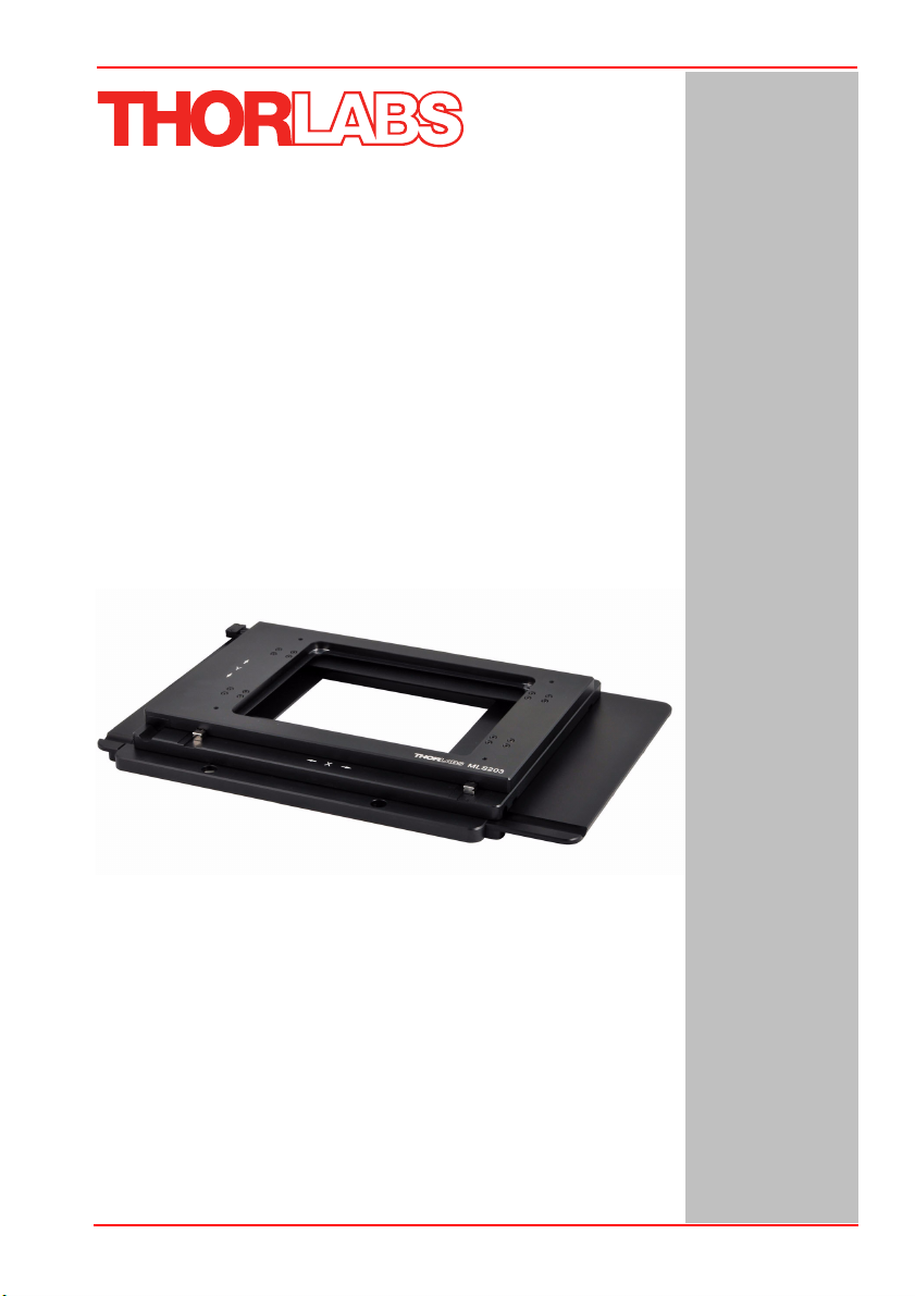
MLS203 Series XY Scanning Stage
Contents
Chaper 1 Overview ..................................................................................................... 1
1.1 Introduction ........................................................................................ 1
Chaper 2 Safety .......................................................................................................... 3
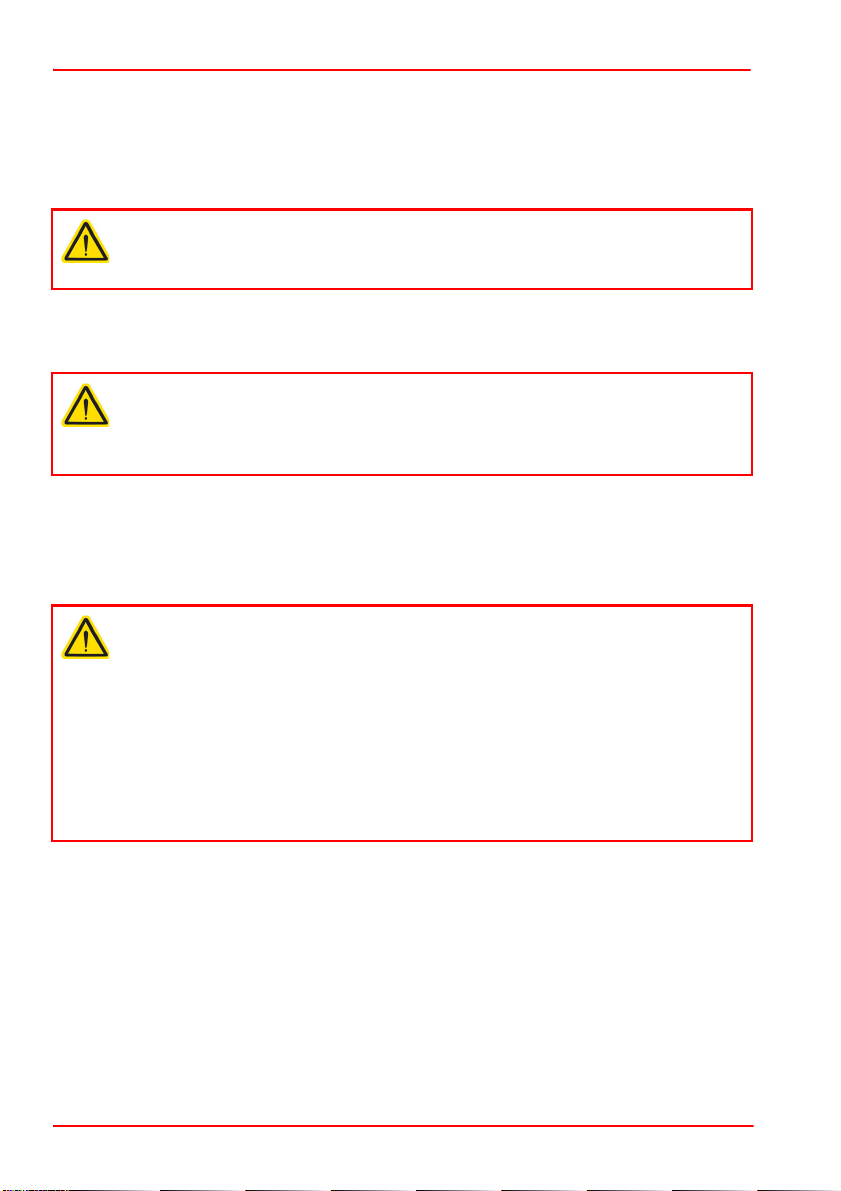
2.1 Safety Information ............................................................................. 3
2.2 General Warnings .............................................................................. 3
Chaper 3 Installation .................................................................................................. 4
3.1 Unpacking ........................................................................................... 4
3.2 Mounting ............................................................................................. 4
3.2.1 General ................................................................................................... 4
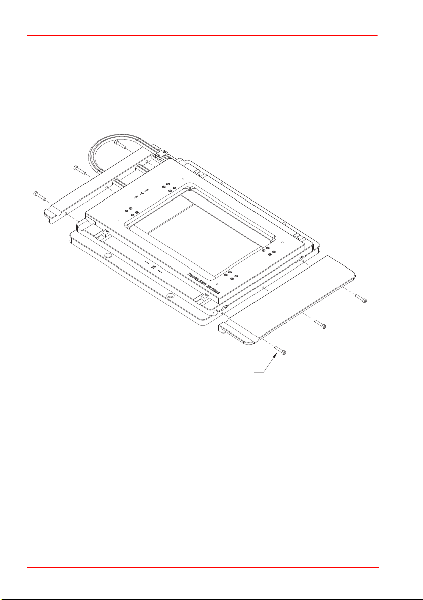
3.2.2 Fitting the Finger Guards ........................................................................ 5
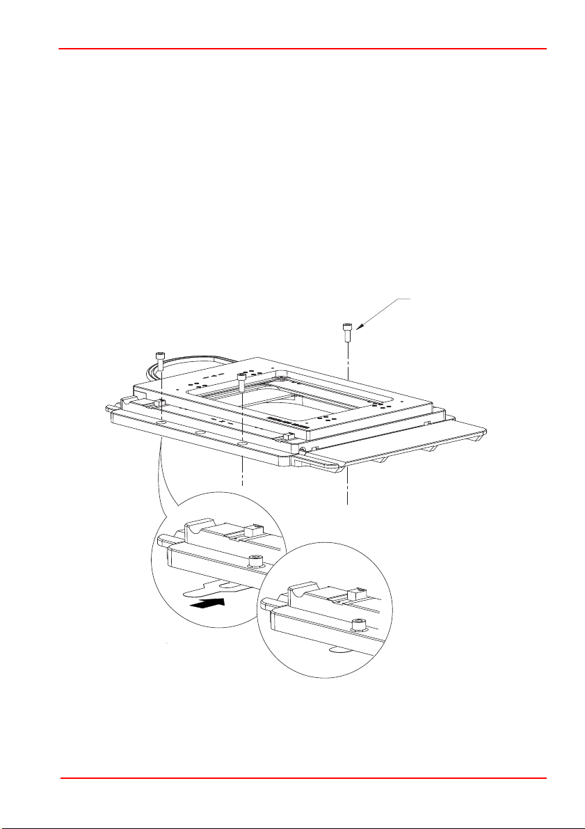
3.2.3 Mounting To Microscope ......................................................................... 5
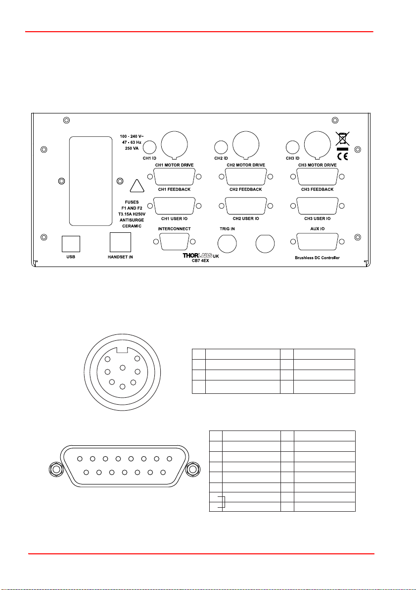
3.3 Electrical Connections ...................................................................... 6
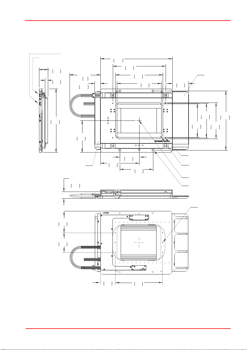
3.4 Dimensions ......................................................................................... 7
3.4.1 MLS203-1 Dimensions ............................................................................ 7
Chaper 4 Operation .................................................................................................... 8
4.1 General ............................................................................................... 8
4.2 Using the Kinesis software ............................................................... 9
4.3 Using the APT software ................................................................... 12
4.4 Position Error Messages. ................................................................ 14
4.5 Transportation .................................................................................. 15
4.6 Maintenance ..................................................................................... 15
4.7 Transportation .................................................................................. 15
Chaper 5 Specification ............................................................................................. 16
Chaper 6 Spares and Accessories .......................................................................... 17
6.1 Parts List ........................................................................................... 17
Chaper 7 Regulatory ................................................................................................ 18
7.1 Declarations Of Conformity ............................................................ 18
7.1.1 For Customers in Europe ...................................................................... 18
7.1.2 For Customers In The USA ................................................................... 18
7.2 CE Certificates ................................................................................. 19
Chaper 8 Thorlabs Worldwide Contacts ................................................................ 20