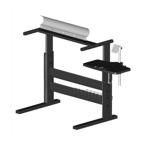
AUTOSENSE™ FLEX STAND
Instructions d’installation et d’utilisation
CARACTÉRISTIQUES GÉNÉRALES
AUTOSENSE FLEX STAND est un support pour le positionnement de lecteurs de
codes à barres de la famille Heron™. Ceci est un dispositif facile d'utilisation, assur-
ant une saisie ferme du scanner, lorsque la numérisation en mode détection
automatique est exigée.
UTILISATION
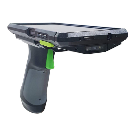
Insérer le lecteur dans son support pistolet comme montré dans l’Image 1. Incliner
le lecteur jusqu’à avoir atteint la position souhaitée de lecture des codes à barres. L’
inclination du pistolet est facilitée par la possibilité de plier à son propre grés le tube
flexible.
ASSEMBLAGE DU «AUTOSENSE FLEX STAND»
Afin d’assembler les pièces du «AUTOSENSE FLEX STAND», veuillez vous référer au
schéma Image 2:
1. Couchez la plaque métallique, tournée vers le haut (2), sur la partie inférieure de
la base en plastique (3).
2. Insérez les trois vis à tête plate (1) pour fixer la base en métal sur la base en
plastique.
3. Vissez le tuyau flexible (4) sur la base en métal et le cache en plastique à tra-
vers la vis (10). Assurez-vous de serrer fermement.
4. Placez le cache en caoutchouc (5) sur le tuyau flexible (4) de manière à le recou-
vrir.
5. Insérez, dans l'ordre, la rondelle plate (7) puis la rondelle élastique (6) dans la
pièce filetée (9), située au niveau de la partie inférieure du support du scanner
(8).
6. Lorsque le support du scanner est serré, orientez-le dans la position souhaitée.
Remarque : le support du scanner peut être placé selon les exigences de l'utilisateur.
INSTALLATION
Veuillez vous référer au schéma Image 2 puis suivez les instructions suivantes:
Fixation avec vis:
1. Vérifiez que l'AUTOSENSE FLEX STAND a été monté correctement.
2. Fixez la base de l'AUTOSENSE FLEX STAND sur la surface souhaitée, conformé-
ment à la procédure suivante.
Le support peut être fixé sur une surface plane, une table ou un plan de travail
par exemple. Il peut aussi être retiré facilement, si nécessaire.
Pour installer le support:
A. Retirez le film protecteur des patins en caoutchouc (11) et faites adhérer les
patins aux zones appropriées sur la partie inférieure du support.
B. Utilisez le gabarit situé au dos de ce manuel pour localiser la position sou-
haitée de la base du support sur la table.
C. Utilisez un stylo pour marquer la position des petits trous (en rouge) sur la
surface de la table. Retirez le gabarit avant d'insérer les vis.
D. Vissez les 2 vis à bois sur la table en centrant les trous marqués. Laissez un
espace d'environ 4 à 5 mm au niveau de la surface supérieure de la table.
E. Posez le support sur les vis en alignant les grands trous (en bleu) aux têtes
des vis.
F. Tournez le support dans le sens inverse des aiguilles d'une montre jusqu'à
la butée.
G. Réglez si nécessaire.
Fixation sans vis:
1. Décollez les trois gommes en caoutchouc (11) et placez-les sous la plaque en
métal.
2. Placez le AUTOSENSE FLEX STAND sur une surface plate et ajustez selon vos
besoins.
AUTOSENSE™ FLEX STAND
Use and installation instructions
BASIC FEATURES
AUTOSENSE FLEX STAND is a bar code scanner holder, belonging to the Heron™
family. It is an operator-friendly device, ensuring a secure grip of the scanner when
auto-sense scanning is required.
USE
Insert the scanner into the stand as shown in Figure 1. Adjust the scanner to the
desired position for reading bar codes by bending the flexible tubing.
AUTOSENSE FLEX STAND ASSEMBLY
To assemble the components of the AUTOSENSE FLEX STAND, please refer to Fig-
ure 2:
1. Place the metal base plate facing up (2) in the bottom of the plastic base (3).
2. Place the 3 flat-head machine screws (1) to fix the metal base plate to the
plastic base.
3. Screw the flex tube (4) to the metal base plate and the plastic cover using the
screw (10). Tighten firmly.
4. Insert the rubber cover (5) into the flex tube (4).
5. Insert the flat washer (7) and then the elastic washer (6) into the threaded
insert (9), located in the bottom part of the cup (8).
6. Screw the cup to the flex tube. When the cup is tightened, orient it in the
desired direction.
Note: The cup may be positioned to suit the user.
INSTALLATION
Refer to Figure 2, then continue as follows.
Attachment with screws:
1. Make sure that AUTOSENSE FLEX STAND is properly assembled.
2. Fix the base of AUTOSENSE FLEX STAND as follows.
The stand can be affixed to a flat surface such as a desk or countertop. If
needed, it can also be easily removed.
To install the stand:
A. Remove the protective film from the rubber feet (11) and adhere them to
the corresponding recessed areas on the bottom surface of the stand.
B. Use the template mask at the back of this manual to locate the desired
position of the stand base on the desk.
C. Use a pen to mark the location of the small holes (shown in red) on the
desk surface. Remove the mask before installing the screws.
D. Screw the 2 wood screws into the desk, centering in the marked holes.
Leave about 4-5 mm of the screw protruding from the upper surface of the
desk.
E. Set the stand in place on the screws by aligning the large holes (circled in
blue) with the screw heads.
F. Rotate the stand counterclockwise until you feel it lock into place.
G. Adjust as needed.
Freestanding:
1. Peel the three rubber pads (11) off the backing sheet and affix them to the
recesses in the bottom side of the Base Cover.
2. Place the AUTOSENSE FLEX STAND on any flat surface and adjust as needed.
AUTOSENSE™ FLEX STAND
Istruzioni di uso ed installazione
CARATTERISTICHE GENERALI
AUTOSENSE FLEX STAND è un sostegno per la collocazione di lettori di codici a barre
della famiglia Heron™. È un dispositivo facile da usare, che garantisce un supporto
sicuro dello scanner nei casi in cui è necessario eseguire la scansione in modalità
automatica “autosense”.
UTILIZZO
Inserire il lettore nell’apposito supporto pistola come mostrato in Figura 1. Orientare
il lettore fino al raggiungimento della posizione desiderata di lettura dei codici a
barre. L’orientamento della pistola è facilitato dalla possibilità di flettere a proprio
piacimento il tubo flessibile.
ASSEMBLAGGIO DI AUTOSENSE FLEX STAND
Per montare i componenti dello stand AUTOSENSE FLEX STAND, fare riferimento
alla Figura 2:
1. Adagiare la piastra di metallo, rivolta verso l’alto (2) nella parte inferiore della
base in plastica (3).
2. Inserire le tre viti a testa piana (1) per fissare la base di metallo alla base di
plastica.
3. Avvitare il tubo flessibile (4) sulla base di metallo e sulla copertura plastica
attraverso la vite (10). Assicurarsi di stringere saldamente.
4. Inserire la copertura in gomma (5) sul tubo flessibile (4) in modo da coprirlo.
5. Inserire in sequenza la rondella piana (7) e successivamente la rondella elastica
(6) nell'inserto filettato (9), situato nella parte inferiore del supporto dello scan-
ner (8).
6. Quando il supporto dello scanner è serrato, orientarlo nella posizione desider-
ata.
Nota: il supporto dello scanner può essere posizionato secondo le esigenze
dell'utente.
INSTALLAZIONE
Riferirsi alla Figura 2 procedendo come di seguito:
Posizionamento con fissaggio:
1. Assicurarsi che l’AUTOSENSE FLEX STAND sia stato assemblato correttamente.
2. Fissare la base del AUTOSENSE FLEX STAND alla superficie desiderata come da
seguente procedura.
Lo stand può essere fissato ad una superficie piatta, ad esempio un tavolo o un
piano di lavoro. Se necessario, può anche essere facilmente rimosso.
Per installare lo stand:
A. Rimuovere la pellicola protettiva dai piedini di gomma (11) e far aderire i
piedini alle aree predisposte nella parte inferiore dello stand.
B. Usare la maschera di template sul retro di questo manuale per localizzare la
posizione desiderata della base dello stand sul tavolo.
C. Usare una penna per segnare la posizione dei fori piccoli (in rosso) sulla
superficie del tavolo. Rimuovere la maschera prima di inserire le viti.
D. Avvitare le 2 viti di legno al tavolo centrando i fori segnati. Lasciare una
sporgenza di circa 4-5 mm dalla superficie superiore del tavolo.
E. Sistemare lo stand sulle viti allineando i fori grandi (n blu) con le teste delle
viti.
F. Ruotare lo stand in senso antiorario fino a che non si blocca in posizione.
G. Regolare se necessario.
Posizionamento libero (privo di fissaggio):
1. Prendere i tre gommini anti-scivolamneto (11) e fissarli sulla parte inferiore
della copertura di plastica.
2. Posizionare l’AUTOSENSE FLEX STAND su qualsiasi superficie piana e regolare
se necessario.

