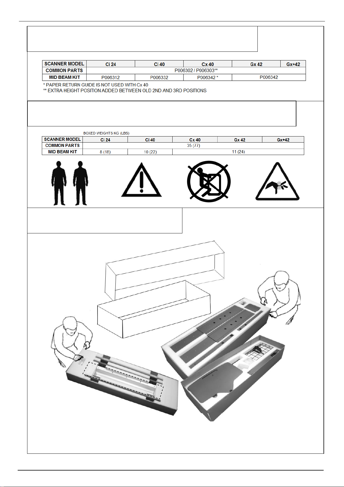
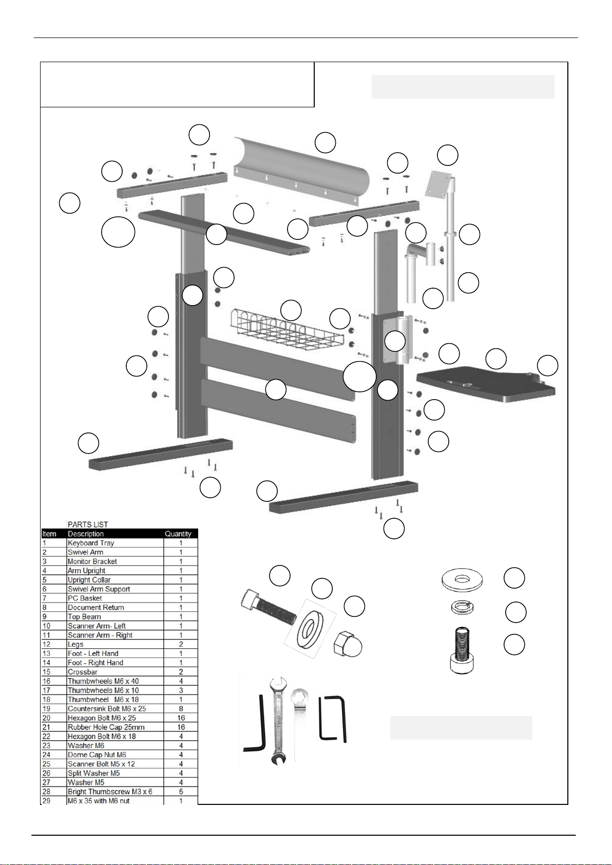
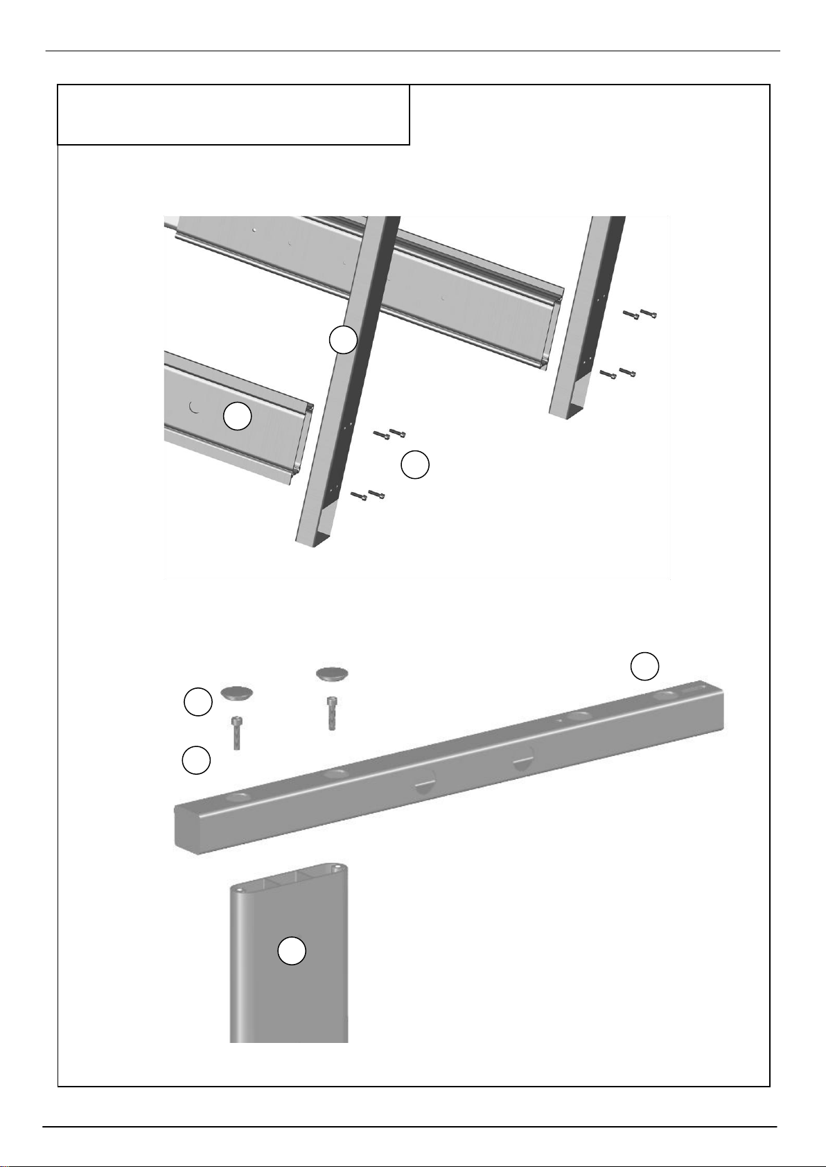
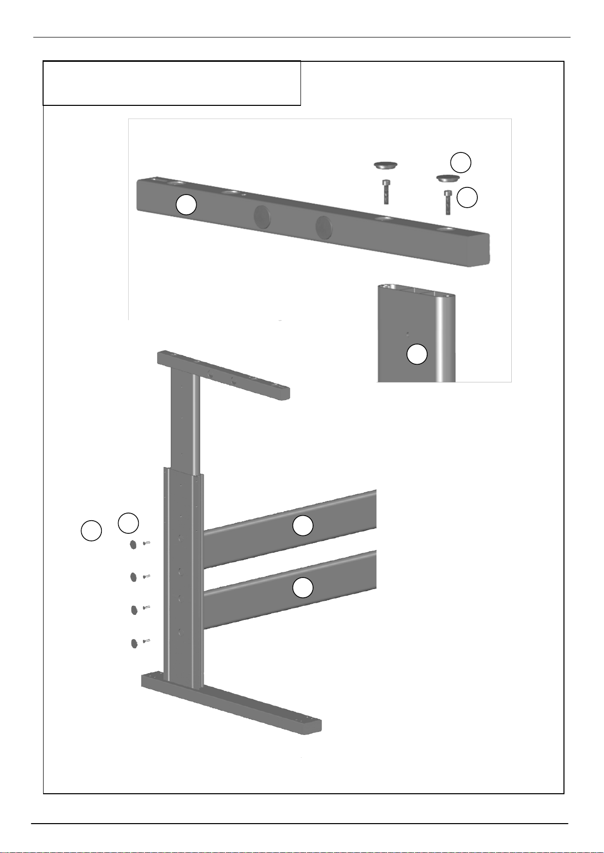
Colortrac MK4 UNIVERSAL REPRO STAND User manual

DOCUMENT P/N: P002253S
PAS 187 Colortrac Ltd © 2010
ASSEMBLY INSTRUCTIONS FOR
MK4 UNIVERSAL REPRO STAND
P/N: P006302/P006303 + P0063x2
SmartLF Gx+ / Gx 42
Ci 24 / 40 Cx 40
(SCANNER ACCESSORY)
Version 1.3 June 2010

Assembly Instructions for SmartLF MK4 Universal Repro Stand P006303
PAS 187 Colortrac Ltd © 2010
2
3. UNPACKING
2. WEIGHTS AND SAFETY
1. PRODUCT PAIRING
P0063x2
MID BEAM SET
Paper Return (dotted) not in Ci set, OR used with Cx models
P006302/P006303
COMMON PARTS
+

Assembly Instructions for SmartLF MK4 Universal Repro Stand P006303
PAS 187 Colortrac Ltd © 2010
3
4. PARTS LIST
20
13
20
15
1
7
16
9
14
8
3
4
5
2
12
12
19
19
6
10
11
16
17
18
20
20
21
21
28
27
26
25
22-24
25-27
LEFT
RIGHT
20
20
22
24
23
DO NOT ATTEMPT TO FIT ITEM 8
TO THE CX 40 SCANNER
SPANNERS ARE SUPPLIED TO
ADJUST STIFFNESS OF MONITOR
TILT. REMOVE PLASTIC CAPS TO
ADJUST (IF NECESSARY)
29
SOME PARTS MAY HAVE
BEEN PRE-ASSEMBLED

Assembly Instructions for SmartLF MK4 Universal Repro Stand P006303
PAS 187 Colortrac Ltd © 2010
4
5. ASSEMBLY
20
14
12
20
10
21
LEFT
12

Assembly Instructions for SmartLF MK4 Universal Repro Stand P006303
PAS 187 Colortrac Ltd © 2010
5
6. ASSEMBLY
11
20
21
12
RIGHT
21
19
15
LEFT
15

Assembly Instructions for SmartLF MK4 Universal Repro Stand P006303
PAS 187 Colortrac Ltd © 2010
6
7. ASSEMBLY
21
9
20
RIGHT
15
21
19
RIGHT
15

Assembly Instructions for SmartLF MK4 Universal Repro Stand P006303
PAS 187 Colortrac Ltd © 2010
7
9
21
20
8. ASSEMBLY
LEFT
6
22-24
RIGHT

Assembly Instructions for SmartLF MK4 Universal Repro Stand P006303
PAS 187 Colortrac Ltd © 2010
8
9. ASSEMBLY
2
18
17
4
5
17
7
RIGHT

Assembly Instructions for SmartLF MK4 Universal Repro Stand P006303
PAS 187 Colortrac Ltd © 2010
9
10. ASSEMBLY
7
3
4
1
8
25-27
28
25-27
29

Assembly Instructions for SmartLF MK4 Universal Repro Stand P006303
PAS 187 Colortrac Ltd © 2010
10
11. ADJUSTMENT

Assembly Instructions for SmartLF MK4 Universal Repro Stand P006303
PAS 187 Colortrac Ltd © 2010
11
12. DIMENSIONS
DIMENSIONS ‘R’ DO NOT APPLY TO Cx 40
mm in mm in mm in
Ws 700 27.6 1100 43.3 1200 47.2
Wo 1536 60.5 1936 76.2 2036 80.2
Dmin 800 31.5 800 31.5 800 31.5
Dmax 948 37.3 948 37.3 948 37.3
Pmin 784 30.9 784 30.9 784 30.9
Pmax 1169 46.0 1169 46.0 1169 46.0
Hmin 1289 50.7 1289 50.7 1289 50.7
Hmax 1449 57.0 1449 57.0 1449 57.0
Kmin 1202 47.3 1202 47.3 1202 47.3
Kmax 1182 46.5 1182 46.5 1182 46.5
Rmin 1046 41.2
Rmax 1431 56.3
Ci 24
Ci 40
Cx 40 / Gx / Gx+

Assembly Instructions for SmartLF MK4 Universal Repro Stand P006303
PAS 187 Colortrac Ltd © 2010
12
All fixings should be checked and re-tightened if necessary after assembly paying particular attention to the bolts fixing the feet (items 13
and 14) to the legs (item 12) and the scanner support arms (items 10 and 11) to the leg uppers (telescopic).
Note: The entire risk of the use or the result of the use of this hardware or documentation remains with the user. No part of this documentation may
be reproduced or transmitted in any means, electronic or mechanical, for any purpose, except with the express prior written permission Colortrac Ltd.
Colortrac Ltd makes no warranty claims with respect to this documentation and disclaims any implied warranties of merchantability or fitness for a
particular purpose. The information contained in this document is subject to change without notice. Colortrac Ltd assumes no responsibility for errors
or omissions that may appear in this documentation.
Document No. P002253S
Version 1.3 June 2010
© Colortrac 2010
This document should not be copied without prior permission from:
Colortrac HQ and Factory
3-5 Brunel Court
Burrel Road
St Ives
Cambridgeshire
PE27 3LW
United Kingdom
Tel: +44 (0) 1480 464618
Fax: +44 (0) 1480 464620
This manual suits for next models
8
Table of contents
Other Colortrac Scanner Accessories manuals