manuals.online logo
Brands
  1. Home
  2. •
  3. Brands
  4. •
  5. aci
  6. •
  7. Transmitter
  8. •
  9. aci OUTSIDE AIR Series Installation instructions

aci OUTSIDE AIR Series Installation instructions

Automation Components, Inc.
2305 Pleasant View Road | Middleton, WI 53562
Phone: 1-888-967-5224 | Website: workaci.com
Page 1
Version: 2.0
I0000857
FIGURE 1: ENCLOSURE
DIMENSIONS
OUTSIDE AIR SERIES
TEMPERATURE TRANSMITTER
Installation & Operation Instructions
Phone: 1-888-967-5224
Website: workaci.com
GENERAL INFORMATION
The ACI Outside Air Series sensors and transmitters
are single point sensors that output 4-20 mA with an
optional voltage signal output of 1-5VDC or
2-10VDC signal to BAS or controller. All ACI/TT and
TTM temperature transmitters can be powered from
either an unregulated or regulated 8.5 to 32 VDC
power supply.
MOUNTING INSTRUCTIONS
For optimal temperature measurement, follow
these tips:
•Avoid mounting to chimney walls, above
windows, above vents, near doors, or dampers.
•Mount at least 1’-2’ (0.3-0.6 m) below eave to prevent
thermal radiation from affecting performance –
see FIGURE 2 (p. 2).
•Mount at least 4’(1.22 m) above ground to prevent
thermal radiation rising up aecting
performance.
•Mount in shade on North side of the structure to
minimize sun exposure. In the Southern
hemisphere the South side of the building is
where the sensor should be mounted.
•The plastic tube that houses the sensor must be
pointed down to avoid debris, water, or ice
potentially aecting sensor performance.
Attach the base directly to the wall. Mounting holes
are located at the corners of the housing – see
FIGURE 1 (right). Drill pilot holes for the mounting
screws. Use the enclosure mounting holes as a
guide, or use the dimensions listed below to
measure out. Install the PG11 watertight fitting
supplied with the sensor if not using conduit. The
outer knockout ring (PG 11/16) on housing
should not be removed when using a ½” NPT
conduit fitting.
Take care when mounting. Sensors should not be
placed in direct sunlight, or any other potential heating
or cooling sources that could aect temperature being
sensed.
SIDE VIEW
FRONT VIEW
NEMA -4X (-4X) BELL BOX (-BB)EURO (-EH)
-4X -BB-EH
MOUNTING HOLE LOCATIONS
-4X -BB-EH
2.55"
(64.77 mm)
2.23"
(56.71 mm)
4.00"
(101.57 mm)
2.12"
(53.72 mm) 2.29"
(58.10 mm)
2.97"
(75.44 mm)
4.70"
(119.46 mm)
4.70"
(119.46 mm) 3.77"
(93.98 mm)
4.72"
(119.83 mm)
4.60"
(116.88 mm)
1.96"
(49.784 mm)
3.11"
(78.99 mm)
2.69"
(68.28 mm)
2.69"
(68.28 mm) 3.18"
(80.77 mm)
3.50"
(88.90 mm)
Automation Components, Inc.
2305 Pleasant View Road | Middleton, WI 53562
Phone: 1-888-967-5224 | Website: workaci.com
Page 2
Version: 2.0
I0000857
+VDC (Red Wire)
4 to 20mA Output
(White Wire)
RTD Wires
(100 Ohm RTD Brown Wires)
(1K Ohm RTD Black Wires)
+VDC (Red Wire)
GND (White Wire)
Voltage Output
(Yellow Wire)
(1 to 5, 2 to 10VDC)
RTD Wires
(100 Ohm RTD Brown Wires)
(1K Ohm RTD Black Wires)
Current Output
(4 to 20 mA)
Current Output
(4 to 20 mA)
Voltage Output
(1 to 5, 2 to 10VDC)
Voltage Output
(1 to 5, 2 to 10VDC)
+VDC
4 to 20mA Output
+VDC
GND
Voltage Output
(1 to 5, 2 to 10VDC)
+-GND VOUT
RTD
+-RTD
SPAN
ZERO
SPANZERO
SPAN
ZERO
SPANZERO
POTTED UNITS
STANDARD UNITS
FIGURE 3: WIRING DIAGRAMS
VAC FIGURE 2: OUTSIDE MOUNTING
WIRING INSTRUCTIONS
PRECAUTIONS
• Transmitter is powered by 24 VDC only.
• Remove power before wiring. NEVER
connect or disconnect wiring with power
applied.
• When removing the shield from the sensor
end, make sure to properly trim the shield to
prevent any chance of shorting.
• When using a shielded cable, ground the
shield ONLY at the controller end. Grounding
both ends can cause a ground loop.
• If the 24 VDC power is shared with devices
that have coils such as relays, solenoids, or
other inductors, each coil must have an MOV,
DC Transorb, Transient Voltage Suppressor
(ACIPart: 142583), ordiode placedacross the
coil or inductor.The cathode, or banded side
of the DC Transorb or diode, connects to the
positive side of the power supply. Without
these snubbers, coils produce very large
voltage spikes when de-energizing that can
causemalfunctionordestructionofelectron-
ic circuits.
Open the cover of the enclosure. ACI recommends
16 to 26 AWG twisted pair wires or shielded cable
for all transmitters. Twisted pair may be used for
2-wire current output transmitters or 3-wire for
voltage output. Refer to FIGURE 3 (right) for wiring
diagrams. All wiring must comply with local and
National Electric Codes. All ACITT and TTM tempera-
ture transmitters can be powered from either an
unregulated or regulated 8.5 to 32VDC power
supply. The TT and TTM DO NOT support an AC
input. All TT and TTM temperature transmitters are
reverse polarity protected. After wiring, attach the
cover to the enclosure.
The minimum voltage at the transmitter power
terminal is 8.5V after load resistor voltage drop.
•249 Ω load resistor (1-5 VDC output) = 13.5 V min supply
voltage
•499 Ω load resistor (2-10 VDC output) = 18.5 V min
supply voltage
Note: Adding extra wire length between the
sensor and transmitter board may aect accuracy.
Recommended 1-2 ft
(0.3-0.6 m) Below Eave
Install Sensor
Downward
Roof
Ground
Automation Components, Inc.
2305 Pleasant View Road | Middleton, WI 53562
Phone: 1-888-967-5224 | Website: workaci.com
Page 3
Version: 2.0
I0000857
FIGURE 5: MULTIPLE TRANSMITTER CONNECTIONS
P
ower Supply
+ -
+ -
+ -
Temp.Transmitter #1
Temp.Transmitter #N
Temp.Transmitter #2
-
VDC
+
Controller
Gnd In1 In2 In3
= Connections
I
n1 = Controller Input #1
I
n2 = Controller Input #2
I
n3 = Controller Input #3
WIRING INSTRUCTIONS (Continued)
Note: All RTD’s are supplied with (2) or (3) ying lead
wires. ACI’s transmitters are supplied with a 2 pole
terminal block for RTD sensor connections. When wiring a
3 wire RTD, connect the (2) common wires (same color)
together into the same terminal block - see FIGURE 4
(right).
Formula for Number of Transmitters
Several transmitters may be powered from the same supply
as shown in FIGURE 5 (below). Each transmitter draws
25mA; refer to the following equation to obtain the number
of permissible transmitters: [# Transmitters] = [Current] /
(25 mA).
FIGURE 4: 3 WIRE RTD
3 WIRE RTD
SAME COLOR WIRES
RTD
TROUBLESHOOTING
TEMPERATURE PROBLEM
No Reading
•No power to board - check voltage at power terminal - should be between +8.5 and 32 VDC.
Reading too Low
•RTD wires shorted. Disconnect wies from terminal block and check with ohmmeter. Reading should be close to 100 Ωor 1 KΩ.
•RTD Improper range of transmitter (too low). Check current or voltage - should be between 4-20 mA, 1-5 V, or 2-10 V.
Reading too High
•RTD opened. Disconnect sensor wires from terminal block and check with ohmmeter. Reading should be close to 100 Ωor 1 KΩ.
•Improper range of transmitter (too high). Check current or voltage - should be between 4-20 mA, 1-5 V, or 2-10 V.
Reading is Inaccurate
•Sensor check: Disconnect sensor wires from terminal block and check with ohmmeter. Compare the resistance reading
to the Temperature vs Resistance curves located on ACI’s website.
•Transmitter check: Make sure sensor wires are connected to terminal block. Determine that the proper output is being
transmitted based on predetermined span:
1. Go to ACI Website, Span to Output Page: http://www.workaci.com/content/span-output
2. Enter the low end of the span
3. Enter the high end of the span
4. Click on the output of the transmitter. This will generate a span to output chart.
5. Measure output of transmitter.
6. Compare measured output to calculated output
PRODUCT SPECIFICATIONS
Automation Components, Inc.
2305 Pleasant View Road | Middleton, WI 53562
Phone: 1-888-967-5224 | Website: workaci.com
Page 4
Version: 2.0
I0000857
WARRANTY
The ACI Outside Air Series sensors and transmitters are covered by ACI’s Five (5) Year Limited
Warranty, which is located in the front of ACI’S SENSORS & TRANSMITTERS CATALOG or can be found
on ACI’s website: www.workaci.com.
W.E.E.E. DIRECTIVE
At the end of their useful life the packaging and product should be disposed of via a suitable
recycling centre. Do not dispose of with household waste. Do not burn.
Note: Transmitter’s calibrated at 71 °F (22 °C) nominal | Note: Thermal Drift is referenced to 71 °F (22 °C) nominal calibration temperature
SENSOR NON-SPECIFIC
Storage Temperature Range:
Lead Length | Conductor Size:
Lead Wire Insulation | Wire Rating:
Conductor Material:
Enclosure Specications: (Operating
Temperature, Material, Flammability,
NEMA/IP Ratings):
SENSOR
Sensor Type | Sensor Curve | Sensing Points:
Sensor Output @ 0°C (32°F):
RTD Tolerance Class | Accuracy:
Din Standard | Temperature Coecient:
Sensor Stability:
Response Time (63% Step Change):
Sensor Operating Temperature Range:
TRANSMITTER
Transmitter Supply Voltage |
Supply Current:
Maximum Load Resistance:
Output Signals:
Calibrated Accuracy | Linearity1:
Thermal Drift2:
Min./Max. CalibratedTemperature Spans:
TTM100/TTM1K Certication Points:
Warm Up Time | Warm Up Drift:
Transmitter Operating Temperature Range:
Transmitter Operating Humidity Range:
Connections | Wire Size:
Terminal Block Torque Rating:
-40 to 71 °C (-40 to 160 °F)
14” (35.6cm) | 22 AWG (0.65mm)
Etched (PTFE) Teon Colored Leads | MIL-W-16878/4 (Type E)
Silver Plated Copper
“-EH”: PC/ASA Plastic w/ UV Protectant; -40 to 88 °C (-40 to 190 °F); UL94-V0
“-4X”: Polystyrene Plastic, -40 to 70 °C (-40 to 158 °F), UL94-V2, NEMA 4X (IP 66)
“-BB”: Aluminum, -40 to 121 °C (-40 to 250 °F), NEMA 3R , UL94-V2, NEMA 4X (IP 66)
Platinum RTD | PTC (Positive Temperature Coecient) | One
A/TT100/TTM100: 100 Ω (Brown/Brown) | A/TT1K/TTM1K: 1 KΩ (Black/Black)
+/- 0.06% Class A | (Tolerance Formula: +/- ºC = (0.15 °C + (0.002 * |t|))
where |t| is the absolute value of temperature above or below 0 °C in °C)
DIN EN 60751 (IEC 751) | 3850 ppm / °C
+/- 0.03% after 1000 Hours @ 300 °C (572 °F)
8 Seconds nominal
-40 to 71 °C (-40 to 160 °F)
+8.5 to 32 VDC (Reverse Polarity Protected) | 25 mA minimum
250 Load: +13.5 to 32 VDC | 500  Load: +18.5 to 32 VDC
(Terminal Voltage - 8.5 V) | 0.020 A
Current: 4-20 mA (2-Wire) | Voltage: 1-5 VDC or 2-10 VDC (3-Wires)
T. Spans < 500 °F (260 °C): +/- 0.2%
T. Spans < 100 °F (38 °C): +/- 0.04%/ °F | T. Spans > 100 °F (38 °C): +/- 0.02%
Min. T. Span: 50 °F (28 °C) | Max T. Span: 400 °F (204 °C)
3 Pt. NIST: 20, 50, & 80% of span | 5 Pt. NIST: 20, 35, 50, 65, & 80% of span
10 Minutes | +/- 0.1%
-40 to 185 °F (-40 to 85 °C)
0 to 90%, non-condensing
Screw Terminal Blocks | 16 AWG (1.31 mm2) to 26 AWG (0.129 mm2)
0.37 ft-lb (0.5 Nm ) nominal

This manual suits for next models

3

Other aci Transmitter manuals

aci Room Series Installation instructions

aci

aci Room Series Installation instructions

aci ACCESS series User manual

aci

aci ACCESS series User manual

aci Room Series Installation instructions

aci

aci Room Series Installation instructions

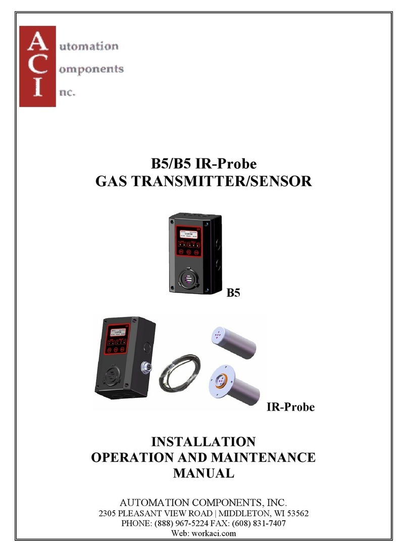
aci B5C User manual

aci

aci B5C User manual

aci CTS-M5 User manual

aci

aci CTS-M5 User manual

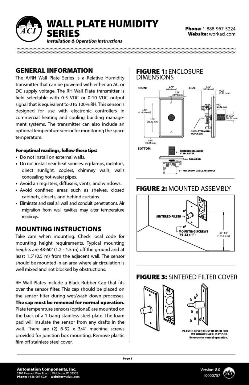
aci WALL PLATE HUMIDITY Series Installation instructions

aci

aci WALL PLATE HUMIDITY Series Installation instructions

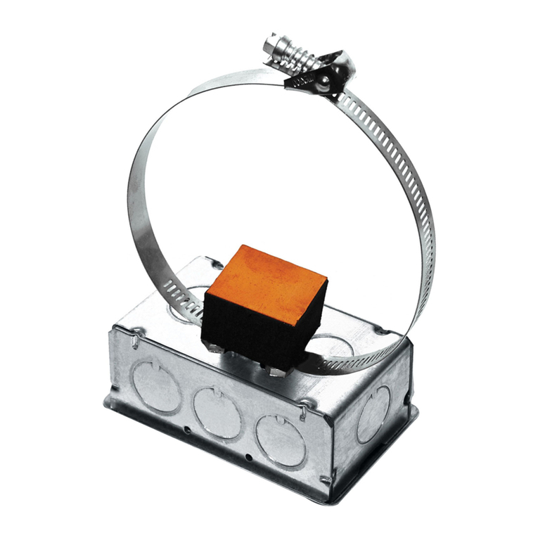
aci DUCT Series Installation instructions

aci

aci DUCT Series Installation instructions

aci STRAP ON Series Installation instructions

aci

aci STRAP ON Series Installation instructions

aci ACCESS series User manual

aci

aci ACCESS series User manual

aci WPR2 Series Installation instructions

aci

aci WPR2 Series Installation instructions

aci ACI/DP Series User manual

aci

aci ACI/DP Series User manual

aci B5 User manual

aci

aci B5 User manual

aci Room Series Installation instructions

aci

aci Room Series Installation instructions

aci Room Series Installation instructions

aci

aci Room Series Installation instructions

Popular Transmitter manuals by other brands

dB PM 1000 user manual

dB

dB PM 1000 user manual

Siemens Sitrans LR250 Compact operating instructions

Siemens

Siemens Sitrans LR250 Compact operating instructions

Nautel NX10 installation manual

Nautel

Nautel NX10 installation manual

MuxLab 500058-WP-UK Quick installation guide

MuxLab

MuxLab 500058-WP-UK Quick installation guide

Vega VEGABAR 82 operating instructions

Vega

Vega VEGABAR 82 operating instructions

Sundrax RadioGate Solid RGS-X-DB-AC user manual

Sundrax

Sundrax RadioGate Solid RGS-X-DB-AC user manual

HETRONIC NOVA-M quick reference

HETRONIC

HETRONIC NOVA-M quick reference

Campbell TX320 instruction manual

Campbell

Campbell TX320 instruction manual

evertz 7700 Series manual

evertz

evertz 7700 Series manual

Omnitronic UHF-400 BP user manual

Omnitronic

Omnitronic UHF-400 BP user manual

Data Video HBT-15 instruction manual

Data Video

Data Video HBT-15 instruction manual

Heathkit SB-401 Assembly manual

Heathkit

Heathkit SB-401 Assembly manual

Sennheiser SK 250 Instrucciones para el uso

Sennheiser

Sennheiser SK 250 Instrucciones para el uso

Edwards CXS instruction manual

Edwards

Edwards CXS instruction manual

Shure AXIENT AXT100 user guide

Shure

Shure AXIENT AXT100 user guide

Retekess TT117 instructions

Retekess

Retekess TT117 instructions

Air Monitor ELECTRA-flo G5 Installation and operation manual

Air Monitor

Air Monitor ELECTRA-flo G5 Installation and operation manual

Harris Broadcast Flexiva FAX 5KW Technical manual

Harris Broadcast

Harris Broadcast Flexiva FAX 5KW Technical manual

manuals.online logo
manuals.online logoBrands
  • About & Mission
  • Contact us
  • Privacy Policy
  • Terms and Conditions

Copyright 2025 Manuals.Online. All Rights Reserved.