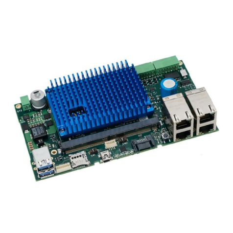
MicroSys Linux 5.10 Yocto SDK User manual

Linux 5.10 Yocto SDK
User Manual
V 2.2

1 Introduction
Thank you for choosing a miriac Single Board Computer from MicroSys. This User
Manual shows the steps needed to boot Linux, to run programs on the SBC,
including your own benchmarks, and also details how to make modifications and
updates to the U-Boot bootloader and/or the Linux kernel to meet your own
requirements.
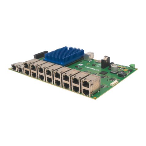
The Linux 5.10.35 Yocto Software Development Kit is valid for the following miriac
Single Board Computers from MicroSys:
SBC-LS1043A
SBC-LS1046A
SBC-LS1088A
SBC-LS1046A-TSN
SBC-LX2160A
AIP-LX2160A
2 Prerequisites
2.1.1 Host Machine Requirements
To operate the board, you will need a host machine with the following capabilities:
■an Ethernet interface to connect to the SBC either directly or via your local
network. In addition, to be able to build a Linux kernel you’ll need an internet
connection.
■a USB port running a terminal software program (e.g. TeraTerm,
HyperTerminal, putty, ckermit...), or else a hardware serial console.
Choose the following parameters:
(a) 115200 Bd
(b) 8 Data bits
(c) No parity
(d) 1 Stop Bit
If you want to build the Linux kernel, you’ll need to have Linux running on your
host. If the host is a Windows machine, then you’ll need to run Linux in
VirtualBox, VMware or a similar virtual machine.

Linux 5.10 Yocto SDK
V2.1
3/25
© MicroSys Electronics GmbH 2022
3 Board Preparation and Power-Up
3.1 CRX05
Make sure that switch SW1-1 is ON and SW1-2 is ON. This is the factory default
and selects the SD card as the boot media.
■Insert the SD card provided into ST1
■The board comes pre-configured to boot correctly on arrival (by default from
SD card)
■Connect the mini USB cable to ST5.
■Connect an Ethernet cable to an RJ45 connector (see table 3-1)
■Connect the power cable to the ST3 connector, while the power supply is still
switched off.
■Open a terminal console on the host PC (set to 115200, 8, N, 1)
■Switch on the power.

Linux 5.10 Yocto SDK
V2.1
4/25
© MicroSys Electronics GmbH 2022
The following picture shows the front view of the two dual RJ-45 connectors as
placed on the CRX05 carrier.
LAN
port
LS1043A
interface
LS1046A
interface
LS1088A
interface
PHY address
1
fm1-mac9
fm1-mac9
dpmac2
0000
2
n/c
fm1-mac6
dpmac3
0001
3
fm1-mac2
fm1-mac5
dpmac7
0010
4
fm1-mac3
fm1-mac3
dpmac4
0011
Table 3-1 Ethernet port to Linux interface assignment
3.2 CRX08
Make sure that switch SW5-1 is ON and SW5-2 is ON. This is the factory default
and selects the SD card as the boot media.
■Insert the SD card provided into ST31
■The board comes pre-configured to boot correctly on arrival (by default from
SD card)
■Connect the mini USB cable to ST29.
■Connect an Ethernet cable to an RJ45 connector (see table 3-1)
■Connect the ATX power cable (24 Pin Molex Mini-Fit) to the ST3 connector
and 8 Pin Molex Mini-Fit to ST5, while the power supply is still switched off.
■Open a terminal console on the host PC (set to 115200, 8, N, 1)
■Switch on the ATX power supply and press the power up button.

Linux 5.10 Yocto SDK
V2.1
5/25
© MicroSys Electronics GmbH 2022
LAN
port
LX2160A
interface
PHY address
1
dpmac17
0x0
2
dpmac18
0x1
3
dpmac3
0x10
4
dpmac4
0x11
5
dpmac5
SFP-25G
6
dpmac6
SFP-25G
4 Operation
After Power-up, the green LED on the module should light up
and any red LED should be off.
IF NOT, DISCONNECT THE UNIT FROM POWER AND CHECK
FOR FAULTS!
4.1 Boot Procedure
When power is supplied the system will boot into U-Boot.
The factory default settings configure U-Boot to boot straight into Linux. So if you
do not intervene, after a few seconds, you will see the Linux prompt:
MicroSys 3.3 mpxls10nn ttyS0
mpxls10xx login:
Enter ‘root’ and hit return. By default, no password is set for root.
mpxls10xx login: root
root@mpxls10xx:~#
You can now enter Linux commands and run programs. Continue in section 2.2

Linux 5.10 Yocto SDK
V2.1
6/25
© MicroSys Electronics GmbH 2022
4.1.1 Only boot into U-Boot
If you want to view the U-Boot parameters, then you will need to prevent U-Boot
from automatically booting into Linux by hitting any key during the autoboot timeout
phase:
. . . . . . . .
PCIe0: pcie@3400000 disabled
PCIe1: pcie@3500000 Root Complex: no link
PCIe2: pcie@3600000 disabled
FM1@DTSEC3 [PRIME], FM1@DTSEC5, FM1@DTSEC6, FM1@DTSEC9
Hit any key to stop autoboot: 0
=>
When you see the U-Boot prompt, =>, you can enter U-Boot commands to change
some parameters, for example your IP address, and view various settings.
=> version // show U-Boot version
=> help // show available commands
=> bdinfo // show board info
=> printenv // show environment variables
=> setenv ipaddr 192.168.1.22 // set environment variable
=> imi // print header information for
application image
=> reset // reboot the board
=> boot // boot OS (in our case: Linux)
Note that the U-Boot environment variables are stored in an I2C EEPROM on the
SoM. This means that if you have updated your boot medium there might be a mis-
match in the envvars which prevents Linux from booting. To update the envvars in
EEPROM enter the following:
=> env default -f -a // fetch defaults from boot medium
=> saveenv // save to EEPROM
If you want to return to U-Boot from Linux, then you need to reboot the board. This
can be done either by power-cycling the board; or pressing the reset button; or, the
most elegant and preferred method, by shutting down and rebooting Linux:
root@mpxls10xx:~# reboot
The system is going down for reboot NOW! (ttyS0) (Fri Aug 20
11:17:00 2021):
INIT: Sending processes the TERM signal

Linux 5.10 Yocto SDK
V2.1
7/25
© MicroSys Electronics GmbH 2022
4.2 Running Linux Programs
Once you see the Linux prompt and have logged on, you can enter Linux com-
mands. Here are some useful commands:
# uname -a // shows Linux kernel version and other info
# ifconfig -a // shows the Ethernet interfaces, including IP addresses
# df // display filesystems
# cat /proc/mtd // shows the partitions in NAND Flash
# reboot // gracefully shutdown Linux and reboot
# shutdown now // shutdown Linux immediately (no reboot)
# restool dpmac info dpmac.17 // show status of the Ethernet port in MC domain
4.2.1 Ethernet Connectivity
One of the first things you are likely to want to do is transfer programs from your
host machine to the SBC target.
By default, the Linux is not configured to use DHCP, therefore no IP address will
have been assigned.
To see the Ethernet interfaces, enter:
root@mpxls10xx:~# ifconfig -a
The SBC-LS1046A and SBC-LS1088A will show 4 Ethernet interfaces and the
SBC-LS1043A will show 3 interfaces.
To assign an IP address to an Ethernet interface, you can either configure the in-
terface manually:
CRX05:
root@mpxls10xx:~# ifconfig fm1-mac3 192.168.0.111 up
CRX08:
root@mpxls10xx:~# ifconfig dpmac17 192.168.0.111 up
Or, to avoid having to enter this every time you boot Linux, you can edit the
/etc/network/interfaces file and add configurations for all the interfaces you
intend to use. For example, here fm1-mac3 is configured to use dhcp:
root@mpxls10xx:~# cat /etc/network/interfaces
# /etc/network/interfaces -- configuration file for ifup(8), if-
down(8)
# The loopback interface
auto lo
iface lo inet loopback
# The fm1-mac3 interface
auto fm1-mac3
iface fm1-mac3 inet dhcp

Linux 5.10 Yocto SDK
V2.1
8/25
© MicroSys Electronics GmbH 2022
Once you can ping the SBC from your host, you can transfer a file to the SBC, for
example a benchmark program. If your host machine is running Windows, we rec-
ommend using WinSCP to transfer files between host and target.
4.2.2 Ethernet Performance
The NXP Layerscape processors contain an Ethernet controller known as DPAA
(Datapath Acceleration Architecture). The LS1043A and LS1046A contain a DPAA
and the LS1088A and LX2160A contain the second generation DPAA2. Further
documentation on the DPAA and DPAA2 can be found in NXP's Reference
Manuals for the corresponding processor and the separate DPAA Reference
Manual.
One of the hardware blocks within the DPAA is the Frame Manager (FMan) –a
functional unit that combines the Ethernet network interfaces with packet
distribution logic to provide intelligent distribution and queuing decisions for
incoming traffic at line rate.
The Frame Manager Configuration Tool (FMC) is a command line tool used to
configure the FMan to perform the desired parse-classify-distribute function for a
given application. The FMC needs to be invoked to improve receive performance
on the Ethernet interfaces.
root@mpxls10xx:~# cd /etc/fmc/config/private/mpxls1046
root@mpxls10xx:~# fmc -c mpxls1046_config.xml -p policy_ipv4.xml -a
4.2.3 Compiling Programs On The Target
If you booted from the SD card, then the default root filesystem already contains a
gcc toolchain (GCC 10.2.0) allowing you to compile natively on the target.
root@mpxls10xx:~# cc helloWorld.c -o hello
This creates an executable with the name hello. To run it:
root@mpxls10xx:~# ./hello
4.2.4 Cross-compilation On The Linux Host
To cross-compile for an ARMv8 target you first need to build the cross-toolchain on
your Linux host. Please refer to section 6.4 Build Toolchain for Cross-compilation.
After you have soured the environment file you can verify the setup and build your
application
$ echo $CC
aarch64-fsl-linux-gcc --sysroot=/home/user/yocto-
sdk/build_mpxls1046/tmp/work/aarch64-fsl-linux/meta-ide-sup-
port/1.0-r3/recipe-sysroot
$ $CC helloWorld.c -o hello
Now you can transfer the executable file hello over to your target and run it there.
Linux 5.10 Yocto SDK
V2.1
9/25
© MicroSys Electronics GmbH 2022
5 Restoring The Default Images
5.1 Boot Media
5.1.1.1.1 CRX05
Per default the board will boot into Linux from the SD card (assuming you have
inserted it correctly). The alternative boot media are provided so that you can
experiment. In addition, they serve as a means of recovery should you accidentally
corrupt or delete any of the boot images. The following table shows how to select
between the three boot media. Note that booting from NAND Flash is only
supported on the MPX-LS1043A.
The accompanying SD card contains a complete U-Boot, Linux kernel and root
filesystem whereas only U-Boot is programmed in the SPI Flash (and also in NAND
on the MPX-LS1043A).
The default images for each boot media are provided on the USB stick delivered
with the Evaluation Kit. The following sections describe how to deploy these
images to the respective boot media.
Copy the build images to your nfsserver directory on a Linux host. If you are
running on a Windows host, then use the directory shared between Windows and
your Linux VM (VirtualBox or VMware). Also for Windows hosts you will need to
have a TFTP server running.
Setting
SW 1-1
SW 1-2
Boot
device
Features
Boot
location
OFF
OFF
QSPI Flash
module
OFF
ON
NAND Flash
module
ON
OFF
SD/MMC
- carrier board
ON
ON
SD/MMC
-
- carrier board

Linux 5.10 Yocto SDK
V2.1
10/25
© MicroSys Electronics GmbH 2022
5.1.2 CRX08
Per default the board will boot into Linux from the SD card (assuming you have
inserted it correctly). The alternative boot media are provided so that you can
experiment. In addition, they serve as a means of recovery should you accidentally
corrupt or delete any of the boot images. The following table shows how to select
between the boot media.
SEL3
SEL2
SEL1
SEL0
Boot Source
Description
0xF
1
1
1
1
Flex-SPI Serial-NOR A
default
0xD
0x9
0x5
0x1
X
X
0
1
SD Card
0x7
0
1
1
1
Flex-SPI Serial-NOR B
Second NOR Flash
(Available only when the
PLL is configured
accordingly)
5.2 Memory Map
This version of the MicroSys Yocto SDK contains major changes to the boot flow
compared to the previous release for the 5.10.35 kernel. This version uses TF-A in-
stead of PPA as used in the previous release.
For a detailed explanation of the changes, it is recommended to read NXP's LSDK
21.08 documentation:
https://www.nxp.com/docs/en/user-guide/LSDKUG_Rev21.08.pdf
The various hardware accelerator blocks in the QorIQ processors, for example
DPAA in the LS1043A and LS1046A or DPAA2 in the LS1088A and LX2160A, re-
quire microcode to be loaded. The memory map is uniform across all the modules
supported by this SDK, but not all the firmware needs to be loaded for a given
module.
Definition
Max
Size
QSPI/NAND
Flash Offset
SD Card
Start Block (hex)
SD Card
Start Block (dec)
bl2.pbl
1MB
0x0000.0000
0x00008
8
fip_uboot.bin
2MB
0x0010.0000
0x00800
2048
DPAA FMan ucode
256KB
0x0001.0000
0x04800
18432
QE Firmware
256KB
0x0094.0000
0x04A00
18944
DPAA2 MC Firmware
3MB
0x00A0.0000
0x05000
20480
DPAA2 DPL
1MB
0x00D0.0000
0x06800
26624
DPAA2 DPC
1MB
0x00E0.0000
0x07000
28672
Table 5-2 Memory Map for Flash and SD Card

Linux 5.10 Yocto SDK
V2.1
11/25
© MicroSys Electronics GmbH 2022
5.3 SD Card
It is advisable to deploy the default images to a second, new microSD card so that
you have a back-up. MicroSys recommends using a microSD card with a capacity
of at least 4GB. The SBC will accept SDHC cards up to 32GB and an SDXC card
of 64GB has also been successfully tested.
The first step involves partitioning your virgin SD card. The second step involves
copying the root filesystem and Image Tree Binary over and the third step is to
copy U-Boot and the various firmware to the SD card.
Step 1) Create a new partition on the SD card.
Insert an SD card in your Linux host and use the dmesg command to determine the
name it has been assigned.
$ dmesg | tail
[118013.491177] sd 4:0:0:2: [sdd] 3921920 512-byte logical blocks:
(2.00 GB/1.87 GiB)
[118013.495020] sd 4:0:0:2: [sdd] Write Protect is off
[118013.495023] sd 4:0:0:2: [sdd] Mode Sense: 43 00 00 08
[118013.499008] sd 4:0:0:2: [sdd] No Caching mode page found
[118013.499011] sd 4:0:0:2: [sdd] Assuming drive cache: write
through
From the above log, we can see that the SD card is /dev/sdd.
Use the df command to see if it has been mounted and, if yes, please unmount it
using the umount command.
Use the fdisk command to create a new partition. (In most cases you can use the
default value with the exception of the first sector which should be at least 131072
blocks since you need to leave space for all the firmware).
# fdisk /dev/sdd
Command (m for help): p
Disk /dev/sdd: 2008 MB, 2008023040 bytes, 3921920 sectors
Units = sectors of 1 * 512 = 512 bytes
Sector size (logical/physical): 512 bytes / 512 bytes
I/O size (minimum/optimal): 512 bytes / 512 bytes
Disk label type: dos
Disk identifier: 0x00000000
Device Boot Start End Blocks Id System
/dev/sdd1 4096 3921919 1958912 83 Linux
Command (m for help): d
Selected partition 1
Partition 1 is deleted

Linux 5.10 Yocto SDK
V2.1
12/25
© MicroSys Electronics GmbH 2022
Command (m for help): n
Partition type:
p primary (0 primary, 0 extended, 4 free)
e extended
Select (default p): p
Partition number (1-4, default 1):
First sector (2048-3921919, default 2048): 131072
Last sector, +sectors or +size{K,M,G} (131072-3921919, default
3921919):
Using default value 3921919
Partition 1 of type Linux and of size 1.9 GiB is set
Command (m for help): w
The partition table has been altered!
Calling ioctl() to re-read partition table.
Syncing disks.
Use the mkfs.ext2 command to format the filesystem (this command will take 4 or 5
secs to complete; user input is not required).
# mkfs.ext2 /dev/sdd1
mke2fs 1.42.9 (28-Dec-2013)
Filesystem label=
OS type: Linux
Block size=4096 (log=2)
Fragment size=4096 (log=2)
Stride=0 blocks, Stripe width=0 blocks
122640 inodes, 489728 blocks
24486 blocks (5.00%) reserved for the super user
First data block=0
Maximum filesystem blocks=503316480
15 block groups
32768 blocks per group, 32768 fragments per group
8176 inodes per group
Superblock backups stored on blocks:
32768, 98304, 163840, 229376, 294912
Allocating group tables: done
Writing inode tables: done
Writing superblocks and filesystem accounting information: done
Step 2) Now mount this partition and copy the rootfs and Image Tree Binary over.

Linux 5.10 Yocto SDK
V2.1
13/25
© MicroSys Electronics GmbH 2022
# mkdir /media/SD
# mount /dev/sdd1 /media/SD
# sudo tar xf microsys-image-networking-mpxls10xx-date.rootfs.tar.gz
-C /media/SD
# cp fitImage.itb /media/SD/boot
Step 3) You still need to copy U-Boot and various microcodes to the SD card.
There are 2 methods to do this. The easiest is to use Linux while you still have your
SD card mounted on your Linux host.
For the LS1043A and LS1046A processors, the procedure is as follows:
# dd if=bl2_sd.pbl of=/dev/sdd bs=512 seek=8
# dd if=fip_uboot.bin of=/dev/sdd bs=512 seek=2048
# dd if=fsl_fman_ucode_ls1043_r1.1_106_4_18.bin of=/dev/sdd bs=512
seek=18432
# dd if=iram_Type_A_LS1021a_r1.0.bin of=/dev/sdd bs=512 seek=18944
For the LS1088A processor, use:
# dd if=bl2_sd.pbl of=/dev/sdd bs=512 seek=8
# dd if=fip_uboot.bin of=/dev/sdd bs=512 seek=2048
# dd if=ddr-phy/fip_ddr_all.bin of=/dev/sdd bs=512 seek=16384
# dd if=mc_app/mc.itb of=/dev/sdd bs=512 seek=20480
# dd if=dpl-eth.19.dtb of=/dev/sdd bs=512 seek=26624
# dd if=dpc-usxgmii.crx08.dtb of=/dev/sdd bs=512 seek=28672
Alternatively, you can insert the SD card into the SBC-LS10xxA and having booted
into U-Boot from QSPI, enter the following commands:
=> setenv loadaddr a0000000
=> tftp bl2.pbl
=> mmc write $loadaddr 8 $filesize
=> tftp fip_uboot.bin
=> mmc write $loadaddr 800 $filesize
=> tftp fman_ucode_ls1046_r1.0_108_4_9.bin
=> mmc write $loadaddr 4800 $filesize
Note that the U-Boot mmc command requires the block number as a hexadecimal
(0x4800 = 18432)

Linux 5.10 Yocto SDK
V2.1
14/25
© MicroSys Electronics GmbH 2022
5.4 QSPI Flash
When programming the QSPI Flash, the RCW needs to be programmed separately
and, for the MPXLS1043A and MPXLS1046A, you must use the swapped version.
The RCW file is to be found in a sub-directory from where the other images are.
For example:
$ cd
$BLD/tmp/deploy/images/mpxls10xxcrxxx/qspi_firmware_mpxls1043.img/
At the U-Boot prompt, edit the serverip address to suit your network and make sure
you are able to ping the server:
=> ping $serverip
=> setenv loadaddr a0000000 // should already be set
=> tftp qspi_firmware.img // download from server
=> sf probe
=> sf erase 0 +$filesize
=> sf write $loadaddr 0 $filesize
=> reset
5.5 NAND Flash
If NAND Flash has been completely deleted or corrupted, meaning there is no U-
Boot output when you power on the board, then you will need to boot into U-Boot
from one of the other boot media in order to restore the contents of NAND Flash.
For an MPX-LS1043A, at the U-Boot prompt, enter the following commands:
=> setenv loadaddr a0000000
=> tftp nand_firmware.img
=> nand erase 0 +$filesize
=> nand write $loadaddr 0 $filesize
=> reset
5.6 XSPI Flash
If Flex-SPI Nor Flash has been completely deleted or corrupted, meaning there is
no U-Boot output when you power on the board, then you will need to boot into U-
Boot from one of the other boot media in order to restore the contents of SPI Nor
Flash.
For an MPX-LX2160A, at the U-Boot prompt, enter the following commands:
=> ping $serverip
=> setenv loadaddr a0000000 // should already be set
=> tftp xspi_firmware.img // download from server
=> sf probe
=> sf erase 0 +$filesize
=> sf write $loadaddr 0 $filesize

Linux 5.10 Yocto SDK
V2.1
15/25
© MicroSys Electronics GmbH 2022
6 Rebuilding U-Boot and Linux
MicroSys uses a Yocto-based Software Development Kit (SDK) for the miriac Sin-
gle Board Computers.
The current release of MicroSys' Linux 5.10 Yocto SDK uses "Yocto Project Core –
Hardknott 3.3". If you are new to Yocto, then documentation to get you started can
be found at https://docs.yoctoproject.org/3.3.4/
The Yocto SDK is maintained by the SoC manufacturer NXP (previously Free-
scale). MicroSys has added patches to cater for the changes made to the MicroSys
hardware. The MicroSys patches are available on the USB stick which was pro-
vided with the miriac SBC.
MicroSys's Linux 5.10.35 Yocto SDK is based on NXP's Layerscape SDK v21.08
and it is advisable to refer to some of the LSDK 21.08 documentation from NXP for
detailed explanations of various features.
Please go to: https://www.nxp.com/lsdk
You will need to download the Yocto SDK if you want to make changes to U-Boot
or the Linux kernel, which will be the case if you want to modify U-Boot and Linux
for your own carrier board. To be able to rebuild the Linux kernel you will need to
have a Linux host machine. If your preferred host machine is running Windows,
then you will need to use VirtualBox or VMware, or something similar, to run Linux.
All popular Linux distributions should work (CentOS, Debian, Fedora, openSUSE,
Ubuntu). A list of supported versions can be found here:
https://docs.yoctoproject.org/3.3.4/ref-manual/system-requirements.html
6.1 Prerequesits
In order to run the build of SDK following packages are required:
chrpath curl diffstat gawk git g++ make python3 python3-distutils software-
properties-common
Git needs to be configured with user name and email address in global settings.
6.2 Installing the Yocto SDK
The Yocto SDK can be found on GitHub at this URL:
https://source.codeaurora.org/external/qoriq/qoriq-components/yocto-sdk
Install the repo utility:
$: mkdir ~/bin
$: curl http://commondatastorage.googleapis.com/git-repo-
downloads/repo > ~/bin/repo
$: chmod a+x ~/bin/repo
$: export PATH=${PATH}:~/bin
Download the metadata:
$: mkdir yocto-sdk

Linux 5.10 Yocto SDK
V2.1
16/25
© MicroSys Electronics GmbH 2022
$: cd yocto-sdk
$: repo init -u
https://source.codeaurora.org/external/qoriq/qoriq-
components/yocto-sdk -b hardknott
$: repo sync --no-clone-bundle
Install MicroSys’ Layer for MPX-Modules:
$ cd /home/$USER/tmp
$ tar -xjf meta-microsys-layerscape-MICROSYS_LSDK_21.08-
4.0.2.tar.bz2
$ cd meta-microsys-layerscape-MICROSYS_LSDK_21.08-4.0.2
$ ./install
Where is the yocto-sdk installed? (/home/$USER/yocto-sdk)
/home/$USER/yocto-sdk
Installing...
Configuring...
Installation complete
[user@localhost MicroSys_Yocto_21.08-3.3]$
$ cd /home/$USER/yocto-sdk
That completes the installation process.
6.3 Building the BSP
To be able to build everything you will need to have internet access from your host
machine since the scripts need to fetch packages from the git repositaries.
Make sure you are in the directory where you installed the SDK. Typically,
/home/$USER/yocto-sdk
The following command will create the build directory for your chosen target. If the
command is invoked with the -h option (help) it lists all the possible target
machines, which are mainly NXP Reference Design Boards. The final targets in the
list should be the MicroSys Single Board Computers. Now invoke the command
with the -m option (machine) and choose the mpxls1043 as your target machine.
$ . ./setup-env -m mpxls1043ac1600msatacrx05
For lx2160a machine
$ . ./setup-env -m mpxlx2160acrx08
For lx2160a machine with Hailo features
$ . ./setup-env -m mpxlx2160acrx08ai

Linux 5.10 Yocto SDK
V2.1
17/25
© MicroSys Electronics GmbH 2022
This will create the build directory and setup the required environment (after you
have scrolled through a long license and accepted the EULA).
$ bitbake microsys-image-networking
The above command will build everything (U-Boot, kernel, root filesystem) and may
take several tens of minutes depending how powerful your host machine is (for the
very first build, this can take several hours). Note that your Linux machine needs
an internet connection for the above command.
Assuming the build is successful, you should see some text similar to the output
below:
. . . . . . . .
meta-openstack-swift-deploy
meta-cloud-services =
"HEAD:d8bc0d92d0f741e2ea1e6d3d9bc6b7a091d03cfb"
meta-security = "HEAD:f9367e71f923fc7d2fb600208e2b97535ea41777"
meta-microsys = "<unknown>:<unknown>"
NOTE: Preparing RunQueue
NOTE: Checking sstate mirror object availability (for 11 objects)
NOTE: Executing SetScene Tasks
NOTE: Executing RunQueue Tasks
NOTE: Tasks Summary: Attempted 3054 tasks of which 2957 didn't need
to be rerun and all succeeded.
[user@localhost build_mpxls1043]$
The exact output may vary, depending on the version of Yocto in use.
Since your build was successful, you will see the resulting images if you change to
the following directory:
[user@localhost mpxls10xx]$ cd ~/yocto-
sdk/build_mpxls10xx/tmp/deploy/images/mpxls10xx
The Image Tree Binary file will have a name similar to:
fitImage.itb
The kernel and root filesystem are the same for all MPX modules supported by this
SDK; only U-Boot and the Device Trees are different between the modules.
Yocto will also generate a complete SD card image which can be copied directly
onto an SD card inserted in the Linux host with the following command:

Linux 5.10 Yocto SDK
V2.1
18/25
© MicroSys Electronics GmbH 2022
$ sudo dd if=microsys-image-networking-machine-
date.rootfs.sdcard of=/dev/$SDX bs=2048 && sync
Where $SDX is the SD card device on your host and can be determined by
invoking the following command after inserting the SD card:
$ dmesg | tail
To rebuild U-Boot on its own the process is similar.
$ bitbake u-boot
If, for example, you have modified the device tree (mpxls1043.dts), the commands
to rebuild this are:
$ bitbake -f -c compile linux-qoriq
$ bitbake microsys-image-networking
6.3.1 Using Devtools to modify recipes.
6.3.1.1 Create Your Own Layer
Before you start modifying recipes it is best to create your own layer which will
contain your changes.
1. If not already done go to the build directory of the machine and call:
$. SOURCE_THIS
This configures and starts bitbake.
2. Go to the sources/ directory and create your layer there:
$ bitbake-layers create-layer --priority 20 meta-mylayer
Note 1: because the priority of meta-microsys-layerscape is 10, it is recommended
to choose a higher number as priority for your own layer (but less than 99).
Note 2: it is a good practice to prefix the layer name with "meta-".
Note 3: this is an optional step. You can remove the directory
recipes-example in the directory meta-mylayer/.
3. Go to the build directory of the machine and add your new layer with:
$ bitbake-layers add-layer ../sources/meta-mylayer

Linux 5.10 Yocto SDK
V2.1
19/25
© MicroSys Electronics GmbH 2022
6.3.1.2 Modifying Linux Kernel
You can modify the sources of Linux kernel using the Yocto tool devtool. This task
assumes that you have created your own layer as described in the section above.
Note that this works for other recipes, too. For example, if you plan to modify the
RCW or U-Boot
use linux-qoriq as recipe name.
1. If not already done go to the build directory of the machine and call:
$ . SOURCE_THIS
This configures and starts bitbake.
2. Call devtool with the recipe for Linux as argument:
$ devtool modify linux-qoriq
This creates a layer called "workspace" which contains the Linux
sources as a GIT repository. The sources can be found in the directory
workspace/sources/linux-qoriq.
Note: if you have done this step before, for example from a previous
modification, then you have to call:
$ devtool modify --no-extract linux-qoriq
with the additional option '--no-extract'. In this case devtool expects that
the source tree already exists.
3. Modify the sources with your favourite editor.
6.3.1.3 Build your Linux with devtool
$ devtool build linux-qoriq
You can find the results in workspace/sources/linux-qoriq/oe-workdir/image/boot.
The resulting linux images are:
- fitImage-5.10.35-3.0+<commit>.itb and device tree binaries.
If you now want to test your new Linux you can create a new boot image with:
$ devtool build-image microsys-image-layerscape

Linux 5.10 Yocto SDK
V2.1
20/25
© MicroSys Electronics GmbH 2022
You can find the output files in tmp/deploy/images/<machinename>.
4. Once you're done with your changes finish your work
- Go to workspace/sources/linux-qoriq and commit your changes using 'git'
- Update the recipe with:
$ devtool finish linux-qoriq meta-mylayer
This copies and saves your changes into meta-mylayer.
If you plan to make more modifications to Linux it's better not to delete
the source tree from the 'workspace' directory. Keep it.
Note: If you think that you are done with all of your changes then you can remove
the recipe from the workspace layer with:
$ devtool reset linux-qoriq
This will **erase all** of your changes from workspace.
5. Now you can rebuild your image including your changes with:
$ bitbake microsys-image-layerscape
Note: if you want to modify the Linux kernel configuration you can call:
$ bitbake -c menuconfig linux-qoriq
Table of contents
Other MicroSys Single Board Computer manuals

MicroSys
MicroSys miriac SBC-LS1046A-TSN User manual

MicroSys
MicroSys miriac SBC-LX2160A User manual

MicroSys
MicroSys miriac MPX-S32G274A User manual

MicroSys
MicroSys miriac MPX-LX2160A User manual

MicroSys
MicroSys miriac SBC-T1024 User manual

MicroSys
MicroSys miriac SBC-S32G274A User manual

MicroSys
MicroSys miriac SBC-T1024 User manual
Popular Single Board Computer manuals by other brands

Ampro
Ampro ReadyBoard 800 Reference manual

MicroSys Electronics
MicroSys Electronics miriac SBC-LS1043A2 user manual

EEPD
EEPD PROFIVE NUCV Hardware reference manual

Lex System
Lex System 2I110D manual

Arbor Technology
Arbor Technology EmETXe-i88U4-D1539 user manual

IEI Technology
IEI Technology SPCIE-C236 user manual