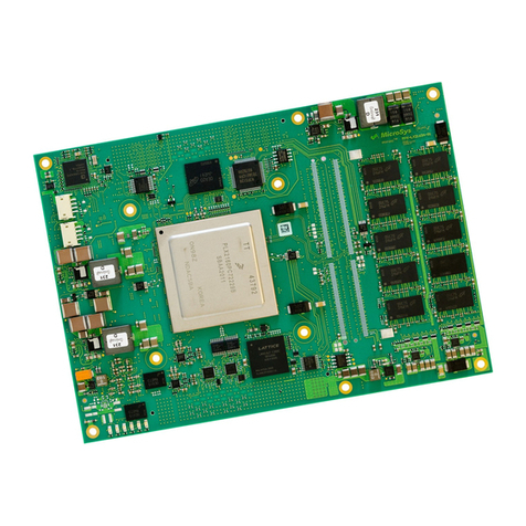
MicroSys miriac MPX-S32G274A User manual

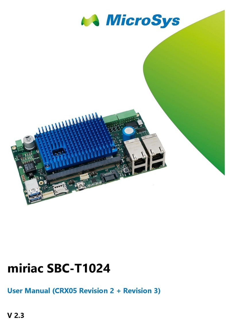
miriac MPX-S32G274A
User Manual (HW Revision 2)
V2.1

Table of Contents
miriac MPX-S32G274AUser Manual
V2.1
2/76
© MicroSys ElectronicsGmbH2020
Table of Contents
1General Notes...................................................3
1.1 Warranty..............................................................3
1.2 Links.....................................................................3
1.3 Liability.................................................................3
1.4Offer to Provide Source Codeof Certain
Software...............................................................4
1.5 Symbols, Conventions and Abbreviations.....5
1.5.1 Symbols...............................................................5
1.5.2 Conventions........................................................5
1.6 Safety and Handling Precautions....................6
2Short Description.............................................7
3System Description.........................................8
3.1 Block Diagram....................................................8
3.2 System Components.........................................8
3.3 Ordering Information..........................................8
3.4 Power Consumption..........................................9
3.5 Cooling.................................................................9
4Technical Description...................................10
4.1 Pinouts...............................................................10
4.1.1 Module Connector –Top Pins.......................10
4.1.2 Module Connector –Bottom Pins..................15
4.2 Power Structure................................................20
4.3 Reset Structure.................................................21
4.4 Clock Structure.................................................22
4.5 Boot Mode Configuration................................25
4.6 LEDs...................................................................26
4.7 RTC....................................................................27
4.8 Temperature sensor........................................28
4.9 GPIO Expander................................................29
4.10 Serial Boot EEPROM (RCON).......................30
4.11 Electronic DIP Switch......................................31
4.12 Interface Description........................................33
4.12.1 Definition of “Primary Interfaces”...................33
4.12.2 JTAG..................................................................33
4.12.3 AURORA ...........................................................33
4.12.4 ADC....................................................................33
4.12.5 CAN....................................................................34
4.12.6 RGMII.................................................................34
4.12.7 ULPI (USB).......................................................35
4.12.8 I2C......................................................................35
4.12.9 QSPI (Flash)......................................................37
4.12.10 SPI......................................................................38
4.12.11 UART..................................................................38
4.12.12 LIN......................................................................38
4.12.13 FlexRay..............................................................38
4.12.14 SDHC.................................................................39
4.12.15 SerDes...............................................................40
5Mechanical Description................................42
5.1 Edge Connector................................................42
5.2 Previous Numbering Scheme.........................43
5.3 Current Numbering Scheme...........................43
5.4 Pin-Layout..........................................................44
5.5 Mounting/Unmounting......................................46
5.6 Board Outline....................................................47
5.7 Height.................................................................48
5.8 Thickness...........................................................48
5.9 Component Layout - Top Side.......................49
5.10 Component Layout –Bottom Side.................51
6Software............................................................53
6.1 U-Boot................................................................53
6.2 Operating System.............................................53
7SafetyRequirements And Protective
Regulations......................................................54
7.1 EMC....................................................................54
7.2 ESD....................................................................54
7.3 Reliability............................................................54
7.4 Climatic conditions...........................................55
7.5 RoHS..................................................................55
8General notes..................................................56
9History...............................................................57
10 Appendix ..........................................................58
10.1 Acronyms...........................................................58
10.2 Table of Figures................................................59
10.3 Table of Tables.................................................60
10.4 Pin Definitions –Top........................................61
10.5 Pin Definitions –Bottom..................................68
10.6 Pins not available for pinmultiplexing...........75
miriac MPX-S32G274AUser Manual
V2.1
3/76
© MicroSys ElectronicsGmbH2020
1 General Notes
Copyright MicroSys Electronics GmbH, January 2020
All rights reserved. All rights in any informationwhich appears in this document
belong to MicroSys Electronics GmbH or our licensors. Youmay copy the
information in this manual for your personal, non-commercial use.
Copyrighted products are not explicitly indicated in this manual. The absence of the
copyright (©) and trademark (TM or ®) symbols does not imply that aproduct is not
protected. Additionally, registered patents and trademarks are similarly not
expressly indicated in this manual.
1.1 Warranty
To the extent permissible by applicable law all information in this document is
provided without warranty of any kind, whether expressed or implied, including but
not limited to any implied warranty of satisfactory quality or fitness fora particular
purpose, orof non-infringement of any third party’s rights. We try to keep this
document accurate and up to date but we do not make any warranty or
representation about such matters. In particular we assume no liability or
responsibility forany errors oromissions in this document.
MicroSys Electronics GmbH neither gives any guarantee nor accepts any liability
whatsoever forconsequential damages resulting from the use of this manual orits
associated product.
MicroSys Electronics GmbH further reserves the right to alter the layout and/or
design of the hardware without prior notification and accepts no liability for doing
so.
1.2 Links
We make no warranty about any other sites that are linked to or from this
document, whether we authorize such links or not.
1.3 Liability
To the extent permissibleby applicable law, in no circumstance, including (but not
limited to) negligence, shall we be liable for yourreliance on any informationin this
document, nor shall we be liable for any direct, incidental, special, consequential,
indirect orpunitive damages nor any loss of profit that result from theuse of, or the
inability to use, this document or any material on any site linked to this document
even if we have been advised of thepossibilityof suchdamage. In no event shall
our liability to you for all damages, losses and causes of action whatsoever,
whether in contract, tort (including but not limited to negligence) or otherwise
exceed the amount, if any, paid by youto us for gaining access to this document.
MicroSys Electronics GmbH
Muehlweg 1
82054 Sauerlach
Germany
Phone: +49 8104 801-0
Fax: +49 8104 801-110

miriac MPX-S32G274AUser Manual
V2.1
4/76
© MicroSys ElectronicsGmbH2020
1.4 Offer to Provide Source Code of Certain
Software
This product contains copyrighted softwarethat is licensed under the General
Public License (“GPL”) and under the Lesser General Public License Version
(“LGPL”). The GPL and LGPL licensed code in this product is distributed without
any warranty. Copies of theselicenses are included in this product.
You may obtain the complete corresponding source code (as defined in the GPL)
for the GPL Software, and/or the complete corresponding source code of the LGPL
Software (with the complete machine-readable “work that uses the Library”) f or a
period of three years afterour last shipment of theproduct including the GPL
Software and/or LGPL Software, which will be no earlier than December 1, 2010,
for the cost of reproduction and shipment, which is dependent on the preferred
carrier and the locationwhere you want to have it shipped to, by sending a request
to:
MicroSys Electronics GmbH
Muehlweg 1
82054 Sauerlach
Germany
In yourrequest please provide theproduct name and versionfor which you wish to
obtain the corresponding source code and your contact details so that we can
coordinatethe terms and cost of shipment with you.
The source code will be distributed WITHOUT ANY WARRANTY and licensed
under the same license as the corresponding binary/object code.
This offeris valid to anyonein receipt of this information.
MicroSys Electronics GmbH is eager to duly provide complete source code as
required under various Free Open Source Softwarelicenses. If however you
encounter any problems in obtaining the full corresponding source code we would
be much obliged if you give us a notification to the email address
gpl@microsys.de, stating theproduct and describing the problem (please do NOT
send large attachments such as source code archives etc. to this email address)

miriac MPX-S32G274AUser Manual
V2.1
5/76
© MicroSys ElectronicsGmbH2020
1.5 Symbols, Conventions and Abbreviations
1.5.1 Symbols
Throughout this document, the following symbols will be used:
InformationmarkedwiththissymbolMUSTbe obeyedto avoidthe risk
of severe injury,healthdanger,or majordestructionof the unit andits
environment
InformationmarkedwiththissymbolMUSTbe obeyedto avoidthe risk
of possible injury,permanentdamageormalfunction of the unit.
Informationmarkedwiththissymbolgivesimportanthintsupondetails
of this manual,orin orderto get the best use out of the productand its
features.
Table 1 Symbols
1.5.2 Conventions
Symbol
Explanation
# / xxx_B
denotesa lowactive signal
←
denotesthe signalflowinthe direction shown
→
denotesthe signalflow in the direction shown
↔
denotesthe signalflowinboth directions
→
denotesthe signalflowinthe direction shownwith additional logic/
additional ICsin the signalpath
I/O / INOUT
denotesa bidirectionalpin
Input
denotesan inputpin
Output
denotesan outputpin
matched
denotesthe accordingsignalto berouted impedancecontrolledand
lengthmatched
Pin 1
refersto the numericpinof a componentpackage
Pin a1
refersto the array position ofa pin withina componentpackage
xxx- / xxx_N
denotesthe negativesignalof a differentialpair
xxx+ / xxx_P
denotesthe positive signalof a differentialpair
xxx
denotesan optionalnotmountedorfitted part
Table 2 Conventions

miriac MPX-S32G274AUser Manual
V2.1
6/76
© MicroSys ElectronicsGmbH2020
1.6 Safety and Handling Precautions
DO NOT exceed the rated maximum values for the power
supply! This may result in severe permanent damage to
the unit, as well as possible serious injury.
ALWAYS keep the unit dry, clean and free of foreign
objects. Otherwise, irreparable damage may occur.
Parts of the unit may become hot during operation. Take
care not to touch any parts of the circuitry during
operation to avoid burns and operate the unit in a well-
ventilated location. Provide an appropriate cooling
solution as required.
Electrostatic discharge (ESD) can damage the unit.
Always take the necessary ESD precautions.
Many pins on the module connector are directly
connected to the SOC or other ESD sensitive devices.
Make or break ANY connection ONLY while the unit is
switched OFF.
Otherwise, permanent damage to the unit may occur,
which is not covered by warranty.
There is no separate SHIELD connection.
The module’s mounting holes are not connected to GND
Take this into account when handling and mounting the
unit.
Table 3 Safetyand Handling Precautions

miriac MPX-S32G274AUser Manual
V2.1
7/76
© MicroSys ElectronicsGmbH2020
2 Short Description
The miriac MPX-S32G274A is a member of theMPX module family based on
NXP’s S32G274A network processor (SoC).
MicroSys Electronics GmbH offers a Development Kit which uses the key features
of the module. The customer can:
■…test the operation of the MPX-S32G274A module
■…evaluate the main interfaces of the S32G274A SoC
■…test the provided software
■…start developing

miriac MPX-S32G274AUser Manual
V2.1
8/76
© MicroSys ElectronicsGmbH2020
3 System Description
3.1 Block Diagram
3.2 System Components
■S32G274A SoC (4x Arm Cortex-A53 plus triple Cortex-M7 lockstep cores)
■4GB LPDDR4 SDRAM
■Serial NOR flash as boot or storage device
■16GB eMMC flash as boot or storage device
■Clock generators for SOCand interface clocks
■I²C EEPROM
■I²C temperature sensor
■I²C RTC
■Voltage regulators for onboard voltages
3.3 Ordering Information
Ordering informationcan befound onthe following website
miriac MPX-S32G274A
or contact yourlocal sales representative.
Figure 3-1 Block Diagram

miriac MPX-S32G274AUser Manual
V2.1
9/76
© MicroSys ElectronicsGmbH2020
3.4 Power Consumption
The MPX-S32G274A is supplied by a single input power rail.
The typical powerconsumption values for the module are determined on a
CRX-S32G carrier running U-Boot (idle) at room temperature with heatsink:
■S32G274A
■Cortex-A53 core frequency 1000 MHz
■400 MHz bus clock
■4 GBytes of LPDDR4 memory + ECC (1600 MHz)
NominalInput
Power
PowerDissipation
9V
2.88 W
12V
2.95 W
18V
3.06 W
24V
3.36 W
30V
3.49 W
Table 4 Typicalpower consumption atU-Bootprompt
3.5 Cooling
In chapter 3.4 the typical power consumption of the MPX-S32G274A module was
specified. Withthis informationa cooling method needs to be designed which
considers the final use case. If desired, MicroSys Electronics GmbH can support
you with your cooling concept. Please ask your sales representative or send an
email inquiry to support@microsys.de.
Component
Temperature
(max.)
PowerDissipation (max.)
SoC
TJ= 125° C
5.1 W
LPDDR4
TC= 95° C
0.4 W
eMMC
TC= 115° C
0.62 W
Table 5 Maximumjunction/casetemperatures
Do not run the module without a heatsink or appropriate cooling concept

miriac MPX-S32G274AUser Manual
V2.1
10/76
© MicroSys ElectronicsGmbH2020
4 Technical Description
4.1 Pinouts
The signal direction is from the module’s view. For example, PCIE0_TX0_N,pin T90, is
an output from the module and an input to peripheral devices on the carrier.
The following table gives an overview of the 314 pins of the module’s edge f inger.
For a detailed connector description see chapter 5.1. The pins will be described in
chapter 4.10 and the following sections.
The signal names in the following two tables do not show all available options for
each pin. Pin multiplexing can only be implemented in combination with the
vendor’s datasheet.
4.1.1 Module Connector –Top Pins
Pin
Pin Name/
Primary Function
Alternate
Functions
GPIO?
T1
GND
---
---
T2
SD_CLK
---
T3
GND
---
---
T4
SD_CMD
---
T5
GND
---
---
T6
SD_D0
---
T7
SD_D1
---
T8
SD_D2
---
T9
SD_D3
---
TK1
VCC_SDHC_1V8/3V3
---
---
TK2
PMIC_FCCU1_OUT
---
---
T10
GND
---
---
T11
GND
---
---
T12
RGMII2_MDC/DSPI0_CS7
T13
RGMII2_MDIO
T14
GND
---
---
T15
RGMII2_RXD3/USB_D7
T16
RGMII2_RXD2/USB_D6
T17
RGMII2_RXD1/USB_D5
T18
RGMII2_RXD0/USB_D4
T19
GND
---
---
T20
RGMII2_RXDV/USB_D3

miriac MPX-S32G274AUser Manual
V2.1
11/76
© MicroSys ElectronicsGmbH2020
Pin
Pin Name/
Primary Function
Alternate
Functions
GPIO?
T21
RGMII2_RX_CLK/USB_D2
T22
GND
---
---
T23
RGMII2_TXD3/USB_D1
T24
RGMII2_TXD2/USB_D0
T25
RGMII2_TXD1/USB_NXT
T26
RGMII2_TXD0/USB_STP
T27
GND
---
---
T28
RGMII2_TX_EN/USB_DIR
T29
RGMII2_TX_CLK/USB_CLK
T30
GND
---
---
T31
RGMII1_MDC
T32
RGMII1_MDIO
T33
GND
---
---
T34
RGMII1_RXD3
T35
RGMII1_RXD2
T36
RGMII1_RXD1
T37
RGMII1_RXD0
T38
GND
---
---
T39
RGMII1_RXDV
T40
RGMII1_RX_CLK
T41
GND
---
---
T42
RGMII1_TXD3
T43
RGMII1_TXD2
T44
RGMII1_TXD1
T45
RGMII1_TXD0
T46
GND
---
---
T47
RGMII1_TX_EN
T48
RGMII1_TX_CLK
T49
GND
---
---
T50
RGMII0_MDC
T51
RGMII0_MDIO
T52
GND
---
---
T53
RGMII0_RXD3
T54
RGMII0_RXD2
T55
RGMII0_RXD1
T56
RGMII0_RXD0

miriac MPX-S32G274AUser Manual
V2.1
12/76
© MicroSys ElectronicsGmbH2020
Pin
Pin Name/
Primary Function
Alternate
Functions
GPIO?
T57
GND
---
---
T58
RGMII0_RXDV
T59
RGMII0_RX_CLK
T60
GND
---
---
T61
RGMII0_TXD3
T62
RGMII0_TXD2
T63
RGMII0_TXD1
T64
RGMII0_TXD0
T65
GND
---
---
T66
RGMII0_TX_EN
T67
RGMII0_TX_CLK
T68
GND
---
---
T69
PCIE1_RX0_N
---
---
T70
PCIE1_RX0_P
---
---
T71
GND
---
---
T72
PCIE1_RX1_N
---
---
T73
PCIE1_RX1_P
---
---
T74
GND
---
---
T75
PCIE0_RX0_N
---
---
T76
PCIE0_RX0_P
---
---
T77
GND
---
---
T78
PCIE0_RX1_N
---
---
T79
PCIE0_RX1_P
---
---
T80
GND
---
---
T81
CLK_OUT_N
---
---
T82
CLK_OUT_P
---
---
T83
GND
---
---
T84
PCIE1_TX0_N
---
---
T85
PCIE1_TX0_P
---
---
T86
GND
---
---
T87
PCIE1_TX1_N
---
---
T88
PCIE1_TX1_P
---
---
T89
GND
---
---
T90
PCIE0_TX0_N
---
---
T91
PCIE0_TX0_P
---
---
T92
GND
---
---

miriac MPX-S32G274AUser Manual
V2.1
13/76
© MicroSys ElectronicsGmbH2020
Pin
Pin Name/
Primary Function
Alternate
Functions
GPIO?
T93
PCIE0_TX1_N
---
---
T94
PCIE0_TX1_P
---
---
T95
GND
---
---
T96
AUR_CLK_N
---
---
T97
AUR_CLK_P
---
---
T98
GND
---
---
T99
AUR_TX2_N
---
---
T100
AUR_TX2_P
---
---
T101
GND
---
---
T102
AUR_TX0_N
---
---
T103
AUR_TX0_P
---
---
T104
GND
---
---
T105
AUR_TX1_N
---
---
T106
AUR_TX1_P
---
---
T107
GND
---
---
T108
AUR_TX3_N
---
---
T109
AUR_TX3_P
---
---
T110
GND
---
---
T111
PB02
T112
PB07
T113
PB08
T114
PB15
T115
PC00
T116
GND
---
---
T117
+VREF1
---
---
T118
+VREF2
---
---
T119
+VREF3
---
---
T120
+VREF4
---
---
T121
GND
---
---
T122
PCIE0_CLKIN_N
---
---
T123
PCIE0_CLKIN_P
---
---
T124
GND
---
---
T125
NMI
---
---
T126
PMIC_RST#
---
---
T127
RSTIN#
---
---
T128
RST#
---
---

miriac MPX-S32G274AUser Manual
V2.1
14/76
© MicroSys ElectronicsGmbH2020
Pin
Pin Name/
Primary Function
Alternate
Functions
GPIO?
T129
GND
---
---
T130
SEL_CLK_RC/EP#
---
---
T131
RCW_SEL#
---
---
T132
MUX_SEL#
---
---
T133
VCC_RTC
---
---
T134
+3V3_EXT
---
---
T135
I2C_SCL_PROG
---
---
T136
I2C_SDA_PROG
---
---
T137
GND
---
---
T138
GND
---
---
T139
GND
---
---
T140
GND
---
---
T141
GND
---
---
T142
GND
---
---
T143
GND
---
---
T144
GND
---
---
T145
GND
---
---
T146
+VIN
---
---
T147
+VIN
---
---
T148
+VIN
---
---
T149
+VIN
---
---
T150
+VIN
---
---
T151
+VIN
---
---
T152
+VIN
---
---
T153
+VIN
---
---
T154
+VIN
---
---
Table 6 Module connector:toppins

miriac MPX-S32G274AUser Manual
V2.1
15/76
© MicroSys ElectronicsGmbH2020
4.1.2 Module Connector –Bottom Pins
Pin
Pin Name/
Primary Function
Alternate
Functions
GPIO?
B1
ADC_CH_11
---
---
B2
ADC_CH_10
---
---
B3
GND
---
---
B4
ADC_CH_09
---
---
B5
ADC_CH_08
---
---
B6
GND
---
---
B7
ADC_CH_07
---
---
B8
ADC_CH_06
---
---
B9
GND
---
---
BK1
PMIC_STBY#
---
---
BK2
PMIC_VDD_OK
---
---
B10
ADC_CH_05
---
---
B11
ADC_CH_04
---
---
B12
GND
---
---
B13
ADC_CH_03
---
---
B14
ADC_CH_02
---
---
B15
GND
---
---
B16
ADC_CH_01
---
---
B17
ADC_CH_00
---
---
B18
GND
---
---
B19
CAN00_RX
---
(INPUT)
B20
CAN00_TX
---
B21
GND
---
---
B22
CAN01_RX
---
(INPUT)
B23
CAN01_TX
---
B24
GND
---
---
B25
CAN02_RX
---
(INPUT)
B26
CAN02_TX
---
B27
GND
---
---
B28
CAN03_RX
---
(INPUT)
B29
CAN03_TX
---
B30
GND
---
---
B31
CAN04_RX
(INPUT)
B32
CAN04_TX

miriac MPX-S32G274AUser Manual
V2.1
16/76
© MicroSys ElectronicsGmbH2020
Pin
Pin Name/
Primary Function
Alternate
Functions
GPIO?
B33
GND
---
---
B34
CAN05_RX
(INPUT)
B35
CAN05_TX
B36
GND
---
---
B37
CAN06_RX
(INPUT)
B38
CAN06_TX
B39
GND
---
---
B40
CAN07_RX
(INPUT)
B41
CAN07_TX
B42
GND
---
---
B43
CAN08_RX
(INPUT)
B44
CAN08_TX
B45
GND
---
---
B46
CAN09_RX
(INPUT)
B47
CAN09_TX
B48
GND
---
---
B49
CAN10_RX
(INPUT)
B50
CAN10_TX
B51
GND
---
---
B52
CAN11_RX
(INPUT)
B53
CAN11_TX
B54
GND
---
---
B55
CAN12_RX
(INPUT)
B56
CAN12_TX
B57
GND
---
---
B58
CAN13_RX
(INPUT)
B59
CAN13_TX
B60
GND
---
---
B61
CAN14_RX
(INPUT)
B62
CAN14_TX
B63
GND
---
---
B64
CAN15_RX
(INPUT)
B65
CAN15_TX
B66
GND
---
---
B67
PA15_DSPI0_SOUT
B68
PA13_DSPI0_SCK

miriac MPX-S32G274AUser Manual
V2.1
17/76
© MicroSys ElectronicsGmbH2020
Pin
Pin Name/
Primary Function
Alternate
Functions
GPIO?
B69
PA14_DSPI0_SIN
B70
PB09_DSPI0_CS1
B71
PB10_DSPI0_CS2
B72
GND
---
---
B73
PA06_DSPI1_SOUT
B74
PA08_DSPI1_SCK
B75
PF15_DSPI1_SIN
B76
PA07_DSPI1_CS0
B77
GND
---
---
B78
PA11_DSPI5_SOUT
B79
PA09_DSPI5_SCK
B80
PA10_DSPI5_SIN
B81
PA12_DSPI5_CS0
B82
JTAG_TCK
---
B83
JTAG_TDO
---
B84
JTAG_TDI
---
B85
JTAG_TMS
---
B86
JCOMP
---
---
B87
GND
---
---
B88
PF03_CLKOUT0
---
B89
PF04_CLKOUT1
---
B90
GND
---
---
B91
FLXR0A_RX_D
B92
FLXR0A_TX_D
B93
FLXR0A_TXEN#
B94
GND
---
---
B95
FLXR0B_RX_D
B96
FLXR0B_TX_D
B97
FLXR0B_TXEN#
B98
GND
---
---
B99
PB12_FXCAN2_RX
B100
PB11_FXCAN2_TX
B101
GND
---
---
B102
PB14_FXCAN3_RX
B103
PB13_FXCAN3_TX
B104
GND
---
---

miriac MPX-S32G274AUser Manual
V2.1
18/76
© MicroSys ElectronicsGmbH2020
Pin
Pin Name/
Primary Function
Alternate
Functions
GPIO?
B105
LIN0_RX
---
(INPUT)
B106
LIN0_TX
B107
GND
---
---
B108
LIN1_RX
(INPUT)
B109
LIN1_TX
B110
GND
---
---
B111
LIN2_RX
(INPUT)
B112
LIN2_TX
B113
GND
---
---
B114
LIN3_RX
---
(INPUT)
B115
LIN3_TX
B116
GND
---
---
B117
PCIE1_CLKC_N
---
---
B118
PCIE1_CLKC_P
---
---
B119
GND
---
---
B120
PCIE0_CLKC_N
---
---
B121
PCIE0_CLKC_P
---
---
B122
GND
---
---
B123
PMIC_FSOUT#
---
---
B124
PMIC_FIN
---
---
B125
VDD_OTP
---
---
B126
PMIC_PWRON1
---
---
B127
PMIC_PSYNC
---
---
B128
PMIC_FOUT/AMUX
---
---
B129
GND
---
---
B130
PC09_UART0_TX
B131
PC10_UART0_RX
B132
GND
---
---
B133
PB01_I2C0_SCL
B134
PB00_I2C0_SDA
B135
PB03_I2C1_SCL
B136
PB04_I2C1_SDA
B137
PB05_I2C2_SCL
B138
PB06_I2C2_SDA
B139
GND
---
---
B140
GND
---
---

miriac MPX-S32G274AUser Manual
V2.1
19/76
© MicroSys ElectronicsGmbH2020
Pin
Pin Name/
Primary Function
Alternate
Functions
GPIO?
B141
GND
---
---
B142
GND
---
---
B143
GND
---
---
B144
GND
---
---
B145
GND
---
---
B146
GND
---
---
B147
GND
---
---
B148
+VIN
---
---
B149
+VIN
---
---
B150
+VIN
---
---
B151
+VIN
---
---
B152
+VIN
---
---
B153
+VIN
---
---
B154
+VIN
---
---
B155
+VIN
---
---
B156
+VIN
---
---
Table 7 Module connector:bottompins

miriac MPX-S32G274AUser Manual
V2.1
20/76
© MicroSys ElectronicsGmbH2020
4.2 Power Structure
The MPX-S32G274A module is supplied by a single 9-30V supply. Onboard
voltages are generated by the PMIC VR5510.
For RTC backup buffering anadditional supply from the carrier is necessary.
The module itself does not provide any supply voltage to the carrier but it has some
reference voltages that show the voltage level of the respective interface on the
module. If necessary, the carrier must track the reference voltages and generate a
copy which can carry higher loads.
The following diagram shows the structure of thepower supplies:
The following table shows the internal connections:
ModuleConnector
Pin
Signal
I/O Range
Description
T146-T154/
B148-B156
VIN
9-30V
Module supply input
T117
+VREF1
1.8V
Referencevoltageoutput
T118
+VREF2
1.8V
Referencevoltageoutput
T119
+VREF3
3.3V
Referencevoltageoutput
T120
+VREF4
3.3V
Referencevoltageoutput
T133
VCC_RTC
0.9V-5.5V
Optional backupsupply
T134
+3V3_EXT
3.3V
Optional bootEEPROMpro-
grammingsupplyinput
B125
VDD_OTP
N/A
Do notconnect
Table 8 Module connector: power pinassignments
Figure 4-1 Power supplies: structure
This manual suits for next models
1
Table of contents
Other MicroSys Single Board Computer manuals

MicroSys
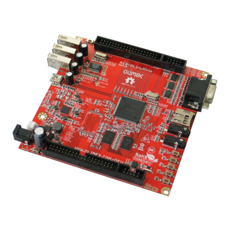
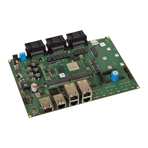
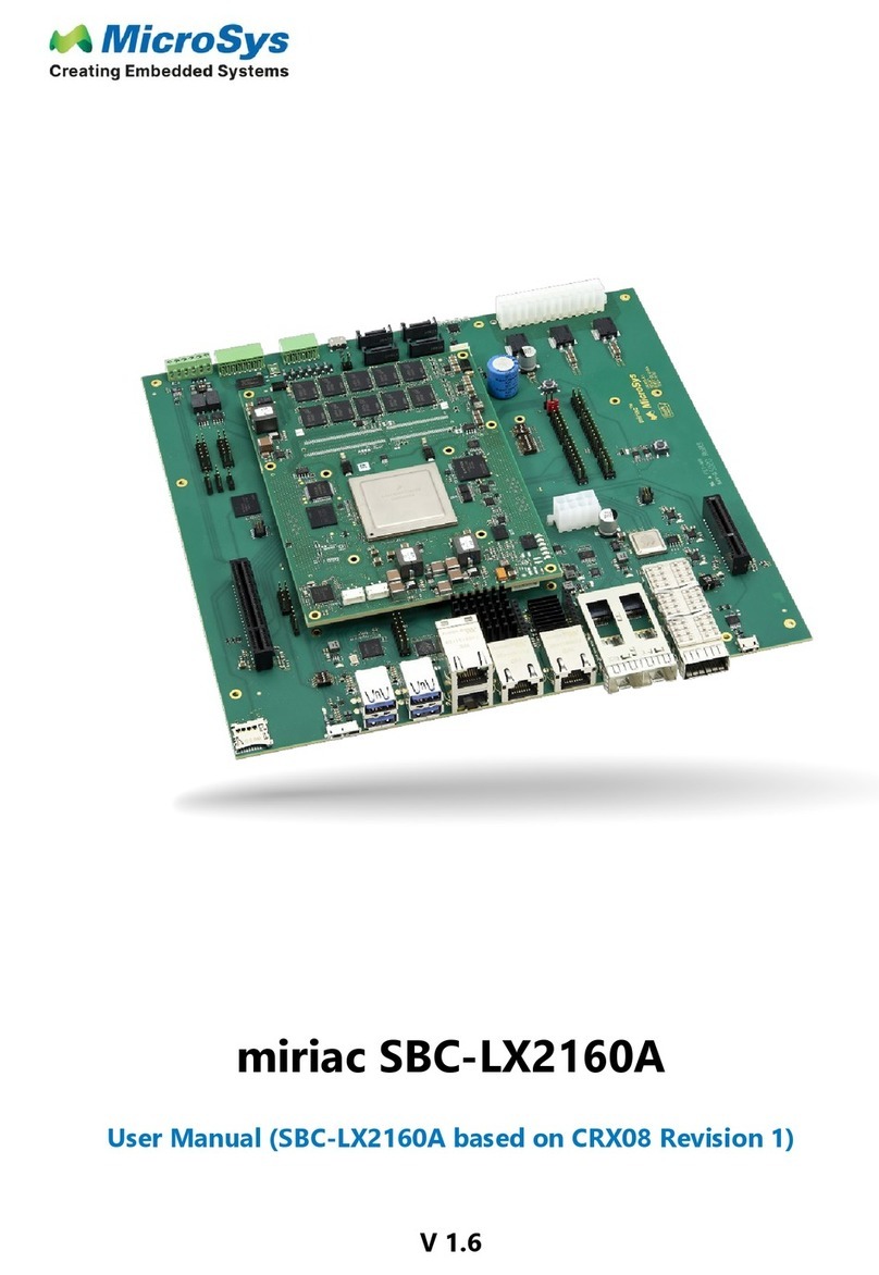
MicroSys miriac SBC-LX2160A User manual

MicroSys
MicroSys miriac SBC-S32G274A User manual

MicroSys
MicroSys miriac SBC-T1024 User manual

MicroSys
MicroSys Linux 5.10 Yocto SDK User manual

MicroSys
MicroSys miriac SBC-T1024 User manual

MicroSys
MicroSys miriac SBC-LS1046A-TSN User manual

MicroSys
MicroSys miriac MPX-LX2160A User manual
Popular Single Board Computer manuals by other brands

WIN Enterprises
WIN Enterprises PL-80910 user manual

DFI
DFI AL551 quick reference

VersaLogic
VersaLogic Fox VL-EPM-19 Programmer's reference manual

Advantech
Advantech MIO-5290L user manual

Artesyn
Artesyn iVPX7225 RTM Installation and use

MicroSys Electronics
MicroSys Electronics miriac SBC-LS1043A2 user manual