5
Installation & Set Up
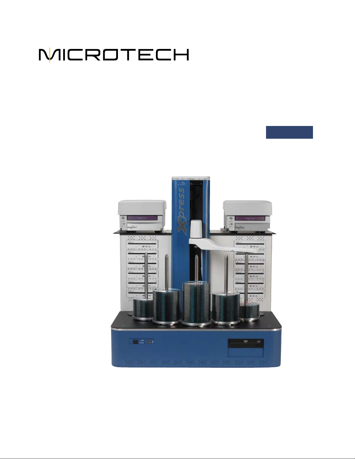
Disc Production Workspace
e workspace for the Xpress XL disc production system should be in an environment
free of dust and debris. Contamination can adversely aect production yield, degrade
the quality of the discs produced, and reduce the life of the equipment. A typical
oce environment will provide the necessary cleanliness, temperature, and humidity
control required to maximize system performance and service life.
e workspace should have the following features:
Sturdy workspace
A working surface sturdy enough to support a total weight of 200 lbs.
Large workspace
A large enough workspace: a recommended minimum of
60” W x 48” D x 36” H, with 36” of clearance above. Also allow enough room on the
workspace for the monitor and keyboard.
Electrical power
e production system needs adequate power and enough power receptacles. Ensure
that the power receptacles are properly grounded. e average power require-
ment for the entire system is 250 watts. e peak requirement may reach 400 watts.
Microtech recommends using a surge protector and/or power conditioner for optimal
setup.
Adequate lighting
ere should be enough light both for operating the equipment and for examining
the discs you produce and print. In addition, if the ImageAligner option is installed,
adequate lighting for the digital camera to capture disc images is recommended.
(Adequate light must be available even when the system is running jobs unattended
aer-hours). Direct sunlight or spotlights can adversely aect the robotic sensors of
the Xpress XL as well as aecting the performance of the ImageAligner.
Document storage
Keep the documentation and soware handy for future assistance, trouble shooting,
etc.
Important Unpacking
Information
Be sure to save all packing
material in case you need to
move or ship your system.
Microtech Systems will
only accept merchandise
returned in the original
shipping container.