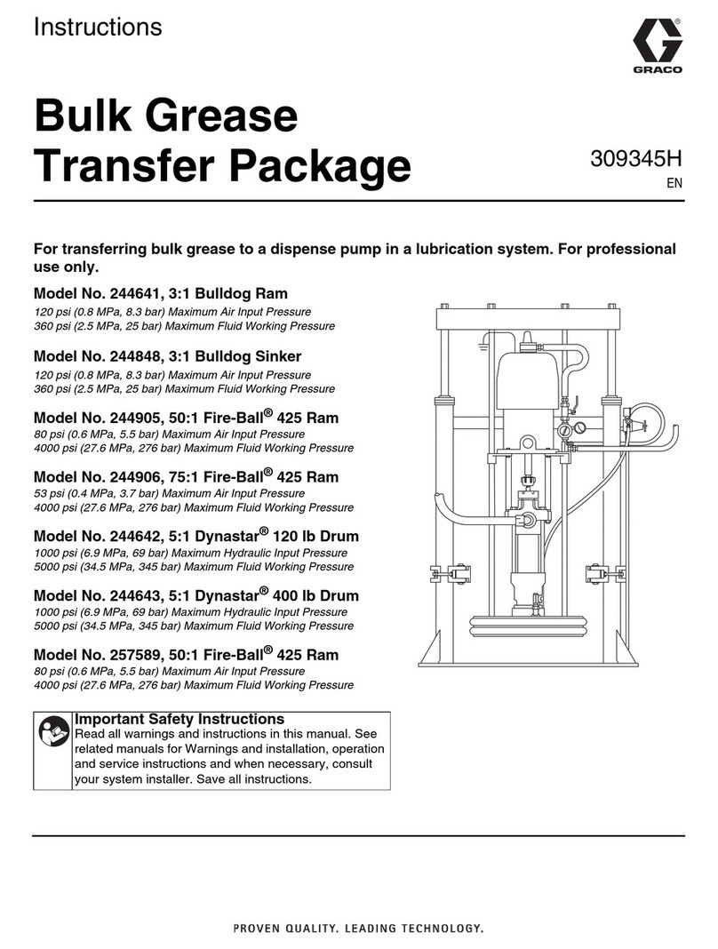
SMW Autoblok W-215 User manual

INSTRUCTION MANUAL
Date:
Version:
Language:
Type W
SHAFT CHUCK
COPY OF THE
ORIGINAL
2018-01
11
English


SMW-AUTOBLOK 3
4
5
6
7
8
10
10
10
10
11
12
13
14
15
15
16
17
19
20
20
20
21
25
31
32
38
39
40
42
45
INSTRUCTION MANUAL
Shaft chuck
Type W
Thank you for purchasing an Original-SMW-AUTOBLOK chuck
type W.
This instruction manual contains the installation, the use and the
maintenance instructions of the work holding „W“.
SMW-AUTOBLOK reserves the right to make changes without
notice.
This instruction manual is a part of the work holding and must
be passed to the new owner in case of sale.
This instruction manual may not be -in whole or in part- copied
without our written agreement.
Content
Please read the instruction manual carefully
before installation and use and always follow the
regulations.
Please note especially the sections which are
marked with the following signs:
• Danger of injury or danger to life if instructions
are not followed.
• Danger of damage to the work holding, the
machine or the components.
Overview
Declaration of incorporation
General safety instructions
Technical data
Ordering review
Description of function
Installation
Check the spindle flange adapter
Check draw tube position (chuck)
Mounting chuck size 215
Mounting chuck from size 260 up
Concentricity / adjustment of the chuck
Mounting the push rod / refilling the oil
Balancing
Operation
Mounting the face driver and jaws
Dismounting the face driver
Adjustment of the face driver
Checklist
Maintenance
Maintenance plan
Checking of oil level
Disassembling the chuck
Assembling the chuck
Views
Spare part list
Calculation formulas for practical use
Trouble shooting
Warranty 12 and 24 months
Documentation of maintenance
Confirmation of receipt of the manual
!

4 SMW-AUTOBLOK
W
29.12.2009
Eckhard Maurer
• DIN EN 1550 (2008)
• DIN ISO 13857 (2008)
Responsible for documentation:
SMW-AUTOBLOK Spannsysteme GmbH
Wiesentalstrasse 28
88074 Meckenbeuren
Deutschland / Germany
Schilling Rainer
Chief designer
Product description:
Application range:
Declaration of incorporation
for an incomplete machine
Machinery Directive 2006/42/EC, Annex II, B
Date:
is intended to be installed into a completed machine. It must not be put into service until the final machine into which
the partly completed machinery it is to be incorporated has been declared in conformity with the provisions of the EU
machine directive (2006/42/EC) Annex II, B.
Applied harmonized norms:
Installation in machine tool
The manufacturer:
herby declares, that the following product:
The following basic requirements of
Annex I, 2006/42/EC are complied with:
• No. 1, 1.1, 1.1.1, 1.1.2, 1.1.3
• No. 1.3.2, 1.3.3, 1.3.4, 1.3.7, 1.3.8
• No. 1.5, 1.6.1
• No. 1.7.1, 1.7.3, 1.7.4
The special technical documents have been created in accordance with Annex VII, Part B. These documents will be
made available electronically on a reasoned request by the national authorities.
Place: Meckenbeuren (Germany)
Declaration of incorporation
President
Type:
Shaft chuck

SMW-AUTOBLOK 5
!
In case of doubts or questions please ask SMW-AUTOBLOK or
one of our authorized offices.
11. Maintenance
The power chuck must be maintained at regular intervals. Check
the conditions by measuring the gripping force with a grip force
meter (e.g. GFT-X with head M4 for 6 jaws).
Replace damaged parts with original SMW-AUTOBLOK spare parts
only.
Maintenance must only be carried out at spindle stop of the
machine.
10. Residual risks
The type of components (shape, weight, unbalance, material
etc.) has a large influence on the system “machine tool - chuck -
component”. For that reason there is always a residual risk.
These residual risks must be considered by the user and must be
eliminated by suitable actions.
9. Crash / damages of the clamping chuck
In case of damage to the chuck, for example, after a collision, use
of wrong top jaws or actuation with unpermitted operating data
the chuck has to be returned immediately for safety reasons to
SMW-AUTOBLOK for inspection.
8. Actuating cylinder
The actuation of the chuck must only be carried out by suitable
cylinders in accordance with safety precautions and regulations.
When installing the chuck on the machine with an existing
cylinder, be sure that the actuating force of the cylinder does not
exceed the max. permitted actuating force of the chuck.
If necessary, reduce the actuating force of the cylinder. Connecting
and adapter parts must be specified for permanent load. Adjust
and check the proximity switches for the stroke control before
starting production.
The adjusted operating pressure / actuating force must be secured
against unauthorized change (for example with a lockable pressure
regulator).
7. Jaws
Always use original SMW-AUTOBLOK top jaws. Jaws of other
manufacturers can cause damage to the chuck or accidents.
SMW-AUTOBLOK top jaws are permanently marked with the max.
allowed actuating force F and the max. speed n.
These values must not be exceeded due to the danger of accidents!
Top jaws must be mounted with socket head cap screws of class
12.9 only. Tighten with the specified torque.
Always ensure sufficient length of thread engagement (min.
1.25 x thread dia.)!
The mounting bolts must be checked for damage and wear in
regular intervals, and have to be replaced if necessary. They have
to be replaced not later than after maximum 100000 clamping
cycles!
At reduced actuating force, the max. speed must also be reduced
accordingly!
6. Max. data for actuating force F and speed n
The data for maximum actuating force F and maximum spindle
speed n are engraved on the chuck body.
5. Safety precautions for the machine
• The machine spindle must only start if the hydraulic pressure
in the cylinder is fully reached and the component is clamped
within the permissible working range.
• Chuck can only be opened when the machine spindle is
stopped.
• A signal must stop the machine spindle in case of a failure of
the clamping pressure and the workpiece must remain safely
clamped until the machine spindle stops.
• Repowering after a power failure must not change the original
clamping mode.
• During machining, the chuck and the clamped component must
be protected by safety guards of the machine.
• Opening the machine door must be possible only when the
machine spindle is completely stopped.
• Maintenance and actuation of the chuck must only be carried
out when the machine spindle is stopped.
2. Demands on operators
SMW-AUTOBLOK chucks must be installed, operated and
maintained only by qualified and regularly trained personnel.
1. Correct use
SMW-AUTOBLOK chucks work safely and trouble free if they are
used according to their specifications i.e. to clamp components on
turning machines.
Any other use can be hazardous.
12. Environment protection
Danger for environment when handling incorrect!
Incorrect handling of environment hazardous materials, especially
the disposal, may result in environmental damage.
• Always follow below instructions.
• In case environmentally hazardous material polluted the
environment always take suitable actions immediately. If in
doubt, inform the local authority about the pollution.
The following hazardous materials are used: Lubricants such as oil
and grease can contain poisonous agents. They must not pollute
the environment. The disposal must be carried out by a suitable
waste management company.
For a proper function of the work holding, use original SMW-
AUTOBLOK lubricant only.
4. Transport
Please use suitable lifting gear for product heavier than 16 kg!
3. Visual inspection
Please check the product for visible damage prior to use!
General safety instructions
Englisch
Danger!
Danger to the environment!
General precept sign!
Follow the instructions! Warning of risk of crushing!
Warning of hand injuries!General warning sign!
Warning of suspended load!
!
!
!
!
!

6 SMW-AUTOBLOK
M=LN
UR
G1
S
G
H
d
b
B
ØC
ØA
G3
a2
a1
Z
h
h1
LN
U
R
M
P
G2
G1
G
ØH
ØE
T
ØS
ØD
W-215 W-260 W-325 W-460
A6 A8 A6 A8 A8 A11 A11 A15
A215 260 325 460
B176 211 238 213 285 251 344 309
CR92 R115 R143 R205
D145 175 220 335
E133.4 171.4 133.4 171.4 171.4 235 235 330.2
GM34 x 1.5 M33 x 1.5 M45 x 1.5 M85 x 2
G1M12 M16 M16 M55 x 2
G2M12 M16 M12 M16 M16 M20 M20 M24
G3M12 x 20 M16 x 24 M20 x 30 M24 x 45
H42 54 70 110
L55/40 20/5 96.5/51.5 121.5/106.5 106/91 140/125 119/104 154/139
M55/-4 20/-39 96.5/26.5 121.5/51.5 106/26.8 140/60.8 119/24.4 154/56.5
N30 42 42 42
P15.5 22 18 21 24 26 26 34
R30 45 50 50
Sf6 15 16.5 16.5 56.5
T22 29 46 60
U10 15 15 15
Z44 53 58 65
Z115 17 22 32.5
a1/a24.5°/1.5° 4.5°/1.3° 4.5°/1.3° 5°/2°
4.0/1.3 4.5/1.3 5.7/1.9 7.7/3.1
5.3 5.8 7.6 10.8
± 0.6 ± 1.0 ± 1.5 ± 3.3
30 36 44 52
65 78 96.5 150.5
50 57 72 88
0.25 0.50 0.75 1.50
0.50 1.00 1.50 3.00
5000 4000 3200 1800
30 55 75 100
60 110 150 200
0.236 0.271 0.639 0.606 1.872 1.734 9.35 8.91
40 45 75 70 140 127 364 336
W
Shaft chuck with retractable jaw carrier
Face driver
Shaft chuck Ø 215 - 460 mm
Piston of
W-215
* When exceeding distance h gripping force/speed must be reduced accordingly.
Subject to technical changes.
For more detailed information please ask our customer service.
SMW-AUTOBLOK Type
Mounting
Chuck outside dia.
Chuck height
In clamping position (radius)
Max. clamping dia.
Push rod face driver min./max.
Min./max.
Push rod pos. check dimension
Axial movement/jaw carrier
Piston stroke for jaw clamping
Opening/residual stroke angle
Opening/residual stroke at distance h1 h1
Max. jaw stroke at distance h* mm
Max. compensating / jaw Type C mm
b
d
Reference height h
Oil volume horizontal use l
Oil volume vertical use l
Max. speed r.p.m.
Max. draw pull kN
Max. grip force at reference distance h* kN
Moment of inertia kg·m2
Weight (without top jaws) kg
Englisch
Main dimensions and technical data
Request or
download:
www.smw-autoblok.de
JAWS-CATALOG

SMW-AUTOBLOK 7
W-215 W-260 W-325 W-460
A6 069930 069527
A8 069932 069444 069525
A11 069815 068981 069602
A15 069600
W-215 W-260 W-325 W-460
A6 069934 069542
A8 069936 069546 069552
A11 069817 069554 069606
A15 069604
W-215 W-260 W-325 W-460
ZHVD-SZ 68-17 110-25 110-25/240-40 240-40
044429 045297 045297/045298 045298
DCN 170-40/95-50
33705215
CGLP ISO VG 68
197859
SMW
AUTOBLOK
Oil: C GLP ISO VG 68
SMW
AUTOBLOK
Oil: C GLP ISO VG 68
W
Type C
Spindle
mounting
Type S
Spindle
mounting
Type
Double
piston cylinder
Id. No.
Id. No.
Oil for permanent oil bath lubrication
Oil specification
Contents 1 liter/1.05 quart (U.S.)
Id. No.
Shaft chuck with retractable jaw carrier
Face driver
Shaft chuck Ø 215 - 460 mm
Supply range:
Self centering clamping (Type S) chuck with mounting bolts and mounting keys, oil*
Actuating cylinder
Oil
* Attention:
The W-chucks in this ordering review are for the use of power operated face drivers only (Type 1).
To use face drivers with spring loaded center, a different chuck (Type 2) has to be used.
Please ask our engineers for the corresponding Id. No. and the matching cylinders.
Power operated face drivers and face drivers with spring loaded center cannot be used alternating on the same chuck.
Attention:
Shaft chuck for vertical machines on request.
Compensating clamping (Type C) chuck with mounting bolts and mounting keys, oil*
Supply range:
Englisch
Ordering review

8 SMW-AUTOBLOK
Description of function
Pushrod for face
driver Chuck piston
Stop bolt (3x) to refill oil in
vertical use (inverted spindle)
Oil fill plug
(horizontal position)
Oil refill plug for vertical
use
Plug for spring
Base jaw
Chuck body
Jaw carrier
Oil level control plug horizontal position
Oil level control plug only at
chucks for vertical use
Mounting key (from chuck size 260 up)Power operated face driver (Version Morse taper, only W-215 /
W-260) with fixed center

SMW-AUTOBLOK 9
W-215 W-260 W-325 W-460
< 0.6 mm < 1 mm < 1.5 mm < 4 mm
Description of function
The shaft chuck type W is available as a compensating or as a self
centering jaw version.
The shaft chuck type W has a retractable jaw carrier to allow
complete machining of shafts in one operation.
It is completely sealed and permanently lubricated by an oil bath.
The face driver is quick change with a taper for centering.
The chuck and the power operated face driver are actuated by a
double piston cylinder.
Conditions:
• The work pieces need to be faced and centered before loading
into to the chuck.
• Runout of the center bores to the clamping dia. can be max. (at
compensating jaw chuck).
The application: Complete machining of shafts in one setup
1. Machine clamping dia. (only necessary when using the self centering chuck):
The jaws are retracted. The component is clamped between centers and driven by the face driver. This operation can be eliminated if
the clamping dia. is already machined when the center bore is manufactured. This operation is not necessary when using the chuck
with fl oating jaws.
2. Rough machining:
The part is driven with the high gripping force of the jaws. High chip removal is possible.
3. Finish machining:
The chuck body is retracted. The part is clamped between centers and driven by the face driver. The complete outline can be
machined with perfect concentricity.
Chuck size
Center offset

10 SMW-AUTOBLOK
3B
3A
21
Installation
Check the spindle flange adapter
Check draw tube position (chuck)
Mounting chuck size 215
Draw bar position!
• The chuck is in a transport position with the jaw carrier
advanced, and the master jaws in a intermediate position.
Check the spindle nose!
• Spindle adapters need to be dialed in to these max. values.
Attention!
• For the chuck W-215, this alternative procedure is valid.
• This chuck size has a different method of installation not requiring the use of a mounting wrench.
• See fig. 3A and 3B only.
Preparation to install W-215
Connect the draw bar thread W-215
• Lift the chuck and position it concentrically in front of the
spindle.
• Remove all plugs with the spring packs from the chuck.
• Rotate the spindle by hand to connect the thread of the draw
bar and the thread of the chuck piston.
• The actuating cylinder has
to be in complete forward
end position (drawtube
fully extended); machine
signal “chuck clamped”.
Check!
• The max. drawpull of the cylinder must not exceed the allowed max. drawpull of the chuck!
• If necessary, drawpull must be reduced and locked to that value.
Confirm prior to installation
Check!
• All adapter parts must be designed for permanet use!

SMW-AUTOBLOK 11
3C
5
4
!
Installation
Mounting chuck from size 260 up
Preparation for installation W-260 / W-325 / W-460
• Lift the chuck and position it concentrically in front of the
spindle.
• Remove all plugs with the spring packs from the chuck.
• Lock the spindle against rotation.
• Screw the rotating drawnut of the chuck into the thread of the
drawbar with the mounting key.
Pull the chuck onto the spindle
• Match the bolt pattern of the chuck mounting bolts to the
threads in the spindle.
• Observe the position of the drive button!
• Switch on the hydraulic power unit of the machine and set it to
the lowest possible pressure.
• Pull the chuck towards the spindle with the lowest force
possible.
Attaching the chuck to the spindle
• Use the long mounting key that comes with the chuck to put
the mounting bolts into the chuck.
• Loosely tighten the mounting bolts.
• Switch on the hydraulic power unit again, and pull the chuck
completely onto the spindle.
Attention!
• Always use safe and appropriate lifting tools!
• Danger of damage!
• Do not cross thread!
• Never apply force!
• Never switch on the spindle drive!

12 SMW-AUTOBLOK
8
10
7
6
W-215 W-260 W-325 W-460
M12 M16 M20 M24
125 250 400 500
W-215 W-260 W-325 W-460
35 35 35 65
9
Installation
Concentricity
Adjustment of the chuck
Insert the plugs with the springs
Attention!
• To dial in the chuck use the lowest actuating pressure possible for the cylinder.
Only low forces must act onto the chuck!
Check the chuck for concentricity
• Position the dial indicator at the outer rim of the body, and
check the chuck for concentricity.
Dial in the chuck
• Adjust in the chuck carefully with a rubber mallet.
TR should be = < 0.005
Mounting the chuck
• Tighten the mounting bolts of the chuck with the correct torque
one after another, after checking the concentricity (pic. 10).
Use the hexogonal bit that comes with the chuck.
• After that double check the concentricity.
• For best concentricity the torque for the individual mounting
bolts can be varieted.
Chuck size
Bolt
Torque (Nm)
Chuck size
Torque (Nm)
Locking the radial chuck runout
• Tighten the locking set screws for the taper locking system.
• Double check the concentricity.

SMW-AUTOBLOK 13
11
12A
215 260 325 460
~250 ml ~500 ml ~1.000 ml ~1.500 ml
~500 ml ~1.000 ml ~1.700 ml ~3.000 ml
W-215 W-260 W-325 W-460
22 29 46 60
20 85 85 85
215 260 325 460
~ 350 ml ~1.700 ml
12B
Installation
Mounting the push rod
Refilling the oil
• Mount the push rod to actuate the face driver with a suiltable
torque wrench. Observe the checking dimension T (see technical
details dim. T) from the front face of the push rod to the front
face of the chuck body. This must be measured with the small
piston of the double piston cylinder in its completet forward
end position.
Oil level control plug
horizontal position
Oil refill plug
horizontal position
Stop bolt (3x) to refill oil
in vertical use (inverted
spindle)
Mounting push rod
Filling the chuck with oil (horizontal, vertical use, inverted spindle)
Refilling of oil (vertical use; the chuck is a special vertical version with an additional oil level control plug)
• Fill the chuck with the oil supplied with the jaw carrier in the
retracted position, the cylinder in the rear position and with the
push rod installed.
• To refill oil put jaw No. 3 in 9.00 O`clock position (on horizontal
machines).
• Oil type: CGLP ISO VG 68
• Oil recommended by SMW-AUTOBLOK: Castrol Gleitbahnöl
Magnaglide D68
Chuck size
Oil qty.
(horizontal)
Oil qty. (vertical use,
inverted spindle)
Chuck size
Dimension (mm)
Torque (Nm)
• Remove one spring pack in position „chuck open“ (chuck piston and jaw carrier retracted
in left end position).
• Close the chuck (Jaws closed and jaw carrier in forward right end position), and fill in oil
according to the table, until oil flows out from the oil control plug.
• Open the chuck again, and install the spring pack again.
Oil control plug vertical use
Chuck size
Oil qty.
(vertical use)
on
request
on
request
Attention!
Information for oil level check can be found on page 20.
Attention!
Information for oil level check can be found on page 21.

14 SMW-AUTOBLOK
W-215 Ø14.0 = 0.6 g Ø16.2 = 0.8 g 13 g 117 g
W-260 Ø14.0 = 0.6 g Ø16.2 = 0.8 g 17 g 153 g
W-325 / W-460 Ø16.2 = 0.8 g Ø20.5 = 2.6 g 39 g 351 g
Installation
Balancing
Balancing weight chambers (9x)
Plug
• For high demands of accuracy and surface quality the chuck must be fine balanced after installation.
• Balancing only with the jaw carrier retracted!
• The chuck has 9 balancing weight chambers equaly spaced arround the jaw carrier.
• The balancing weight chambers are filled with washers.
• Check the imbalance of the chuck with a suitable balancing unit.
• Eliminate the imbalance measured by removing washers accordingly.
• Put a little grease into the chamber after removing the washers to eliminate rattling.
Weight per washer Weight per chamber Total weight

SMW-AUTOBLOK 15
3
2
1
W-215 W-260 W-325 W-460
M12 M16 M20 M24
100 200 400 500
Operation
Mounting the face driver
Attention!
• Always use a torque wrench.
• Original SMW-AUTOBLOK top jaws have capture bolts.
• Clean the mounting faces of the master jaws and the top jaws
thorougly. When bolting the top jaws to the master jaws the
spring loaded pin in the master jaw automaticly pushes the top
jaw against the radial location shoulder.
• Allways observe correct seating of the top jaws on the master
jaws.
Face driver (Version Morse taper)
• Clean the inside taper of the chuck and the outside taper of the
face driver thoroughly.
Even smallest particles can cause runout!
• Do not oil the taper!
• Mount the face driver to the chuck using the mounting
wrench that comes with the chuck. Observe the position of
the orientation slot. Tighten the locking nut with the mounting
wrench.
• Reachable runout on the center point 0.02mm TIR!
Mounting the face driver (Version Morse taper)
• To achive a perfect concentricity use a work piece to push
against the face driver using the force of the tailstock. After that
manually retighten the locking nut with the mounting wrench.
Do not use a hammer or extensions.
Mounting the top jaws W-215 / W-260 / W-325 / W-460
Mounting the face driver (Version Morse taper) and the top jaws W-215 / W-260
Chuck size
Bolt
Torque (Nm)

16 SMW-AUTOBLOK
2
1
Operation
Dismounting the face driver
Dismounting the face driver (Version Morse taper) W-215 / W-260
Face driver (Version Morse taper)
To remove the face driver, first remove the top jaws.
• Use the mounting wrench to open the locking nut.
• In order to help guid the mounting wrench, the jaw carrier can
be brought into its forward, end position.
Face driver and guide sleeve (Version Morse taper)
• In order to have a better guide for the wrench, especially when removing the face driver, use the guide sleeve on the outside dia. of
the face driver.
• The ID of the sleeve matched to the OD of the corresponding face driver.
Face driver
Guide sleeve
Wrench

SMW-AUTOBLOK 17
1
2
W-215 W-260 W-325 W-460
M6 M6 M8 M10
15 15 36 72
!
Operation
Adjustment of the face driver
(Standard)
Face driver (Version short taper not adjustable)
Standard: Mounting of the face driver: Version short taper, radialy not adjustable
(Radialy not adjustable = short taper of the face driver with tight fit to the short taper of the chuck for self centering installation)
Cover wedge
Power operated drive pin
Capture mounting bolts Removable center
Mounting of the face driver (Version short taper not adjustable)
• Tighten the bolts alternately. Double check the concentricity.
• Reachable runout on the center point 0.02mm TIR!
Chuck size
Bolt
Torque (Nm)
Attention!
• Danger of injury! Cover the driving pins / centerpoint or use suitable protection gloves when changing the face driver!

18 SMW-AUTOBLOK
4
2
3
1
W-215 W-260 W-325 W-460
M6 M6 M8 M10
15 15 36 72
!Attention!
• Do not overtighten the bolts of the locking wedges. The bolts can break! The face driver will be locked in the chuck!
• Danger of injury! Cover the driving pins / centerpoint or use suitable protection gloves when changing the face driver!
Face driver (Version short taper adjustable)
• Insert the face driver into the chuck and loosely tighten the
mounting bolts.
Option: Mounting and adjusting of the face driver: Version short taper, radialy adjustable
(Radialy adjustable = short taper of the face driver with clearence to the short taper of the chuck for manual radial fine adjustment)
Mounting and adjusting of the face driver (Version short taper adjustable)
• Check the runout of the center point with a dial indicator.
Adjust the runout by using a rubber mallet.
TIR=< 0.005 mm (Only when using the version for an adjustable
face driver).
Mounting and adjusting of the face driver (Version short taper adjustable)
Locking wedge
Power operated drive pin
Capture mounting bolts Removable center
Mounting and adjusting of the face driver (Version short taper adjustable)
• Tighten the bolts alternately. Double check the concentricity.
• Insert the locking wedges and tighten with max. 3.5 Nm torque.
Double check the concentricity.
Chuck size
Bolt
Torque (Nm)
Operation
Adjustment of the face driver
(Optional)

SMW-AUTOBLOK 19
Checklist
Before starting production check the following:
Top jaws
• Are the mounting bolts of the top jaws tightened properly?
• Retighten the mounting bolts with a torque wrench if needed!
• Does the clamping diameter of the jaws match the work piece dia.?
• Is there enough residual jaw stroke?
Clamping pressure
• Does the hydraulic pressure and the resulting grip force match the data engraved on the top jaws?
• Never exceed the values stated on the top jaws!
Speed
• Does the max. speed in the CNC program match the max. speed engraved on the top jaws?
• Never exceed the values stated on the top jaws!
Face driver
• Is the concentricity of the center point of the face driver correct?
• Is the locking nut tightened correctly?
• Retighten if necessary.
Imbalance
• Is there any vibration caused by imbalance?
• Increase the spindle speed to machining speed in small increments and eliminate imbalance if needed.
Operation
Checklist

20 SMW-AUTOBLOK
•
•
•
•
•
•
215 260 325 460
~ 250 ml ~ 500 ml ~ 1000 ml ~ 1500 ml
~ 500 ml ~ 1000 ml ~ 1700 ml ~ 3000 ml
100 ml 200 ml 400 ml 800 ml
Maintenance
Maintenance plan
Checking of oil level
Attention!
• Regular maintenance is important for the safe function, long lifetime, precision and grip force of the chuck.
• Check the grip force of the chuck regularly with the SMW-AUTOBLOK GFT-X grip meter!
• Do not use any liquids that can damage or destroy the chuck seals!
• Make sure the coolant used will not damage or destroy the chuck seals!
Maintenance plan
* Advice for checking method: At lowest hydraulic pressure possible, the jaw carrier and the master jaws must move smoothely
without chattering.
Checking of oil level (horizontal and vertical use)
Refill oil (on horizontal machines)
1. Bring the oil refill plug to the12.00 O`clock position.
Jaw No. 3 will be in 9.00 O`clock position.
2. Open the oil refill and the oil level control plug.
3. Refill oil (CGLP ISO VG 68) until it flows out from the oil control
plug port.
4. Close the oil refill and the oil level control plug.
Attention!
Checking the oil level must be carried out only when the jaw
carrier is fully retracted!
Refill oil (on vertical machines with inverted spindle)
1. Open one (only one out of the 3) stop bolts.
2. Refill oil (CGLP ISO VG 68) until it flows out from the oil refilling
plug port (bottom edge of port).
3. Close the stop bolt port.
Oil level control plug horizontal
position
Oil fill plug
horizontal position
Jaw 3 in 9:00
o‘clock position
In 12:00 o‘clock position
Stop bolt (3x) to refill oil
in vertical use (inverted
spindle)
Attention!
• Wear of the seals can increase normal oil consumption!
• In case the refill volume exceeds the max values in the table below, the chuck must be checked and the seals must be changed.
daily weekly monthly yearly
Visible leakage
Oil level check / refill oil
Measuring of grip force
Cleaning outside
Check jaw carrier and master jaws for smooth movement *
Revision consisting of: Disassembling the chuck, Changing all seals and
wear parts, Checking for cracks, Refilling with fresh oil
Chuck size
Oil qty. (horizontal)
Oil qty. (vertical use, inverted spindle)
Max. oil consumtion / refill volume
This manual suits for next models
3
Table of contents
Other SMW Autoblok Industrial Equipment manuals
SMW Autoblok
SMW Autoblok F180 User manual

SMW Autoblok
SMW Autoblok Mario Pinto LT Operation instructions
SMW Autoblok
SMW Autoblok VNK 70-37 Operation instructions
SMW Autoblok
SMW Autoblok M30 IOL User manual
SMW Autoblok
SMW Autoblok ZHVD-SZ User manual
SMW Autoblok
SMW Autoblok KNCS-NB User manual
SMW Autoblok
SMW Autoblok APS User manual
SMW Autoblok
SMW Autoblok SLX e-motion User manual
