Microtest 8740 User manual

1
Table of Content
Chapter 1. Precautions ...........................................................................................................................3
1.1 Safety Signs ...............................................................................................................................3
1.2 Do not modify or make internal adjustments to this machine...................................................3
1.3 Static Electricity.........................................................................................................................3
1.4 Ground.......................................................................................................................................3
1.5 Power.........................................................................................................................................3
1.6 Warm Up....................................................................................................................................3
1.7 Machine Malfunction.................................................................................................................4
1.8 Test End .....................................................................................................................................4
1.9 Placement and Storage...............................................................................................................4
1.10 Emergency Handling .................................................................................................................4
Chapter 2. General description .............................................................................................................5
2.1 Package and Accessories ...........................................................................................................5
2.2 Description of Nouns and Symbols Used in This Manual.........................................................5
2.3 Basic Operations of the Tester...................................................................................................6
2.4 Front and Rear Panel Functions.................................................................................................7
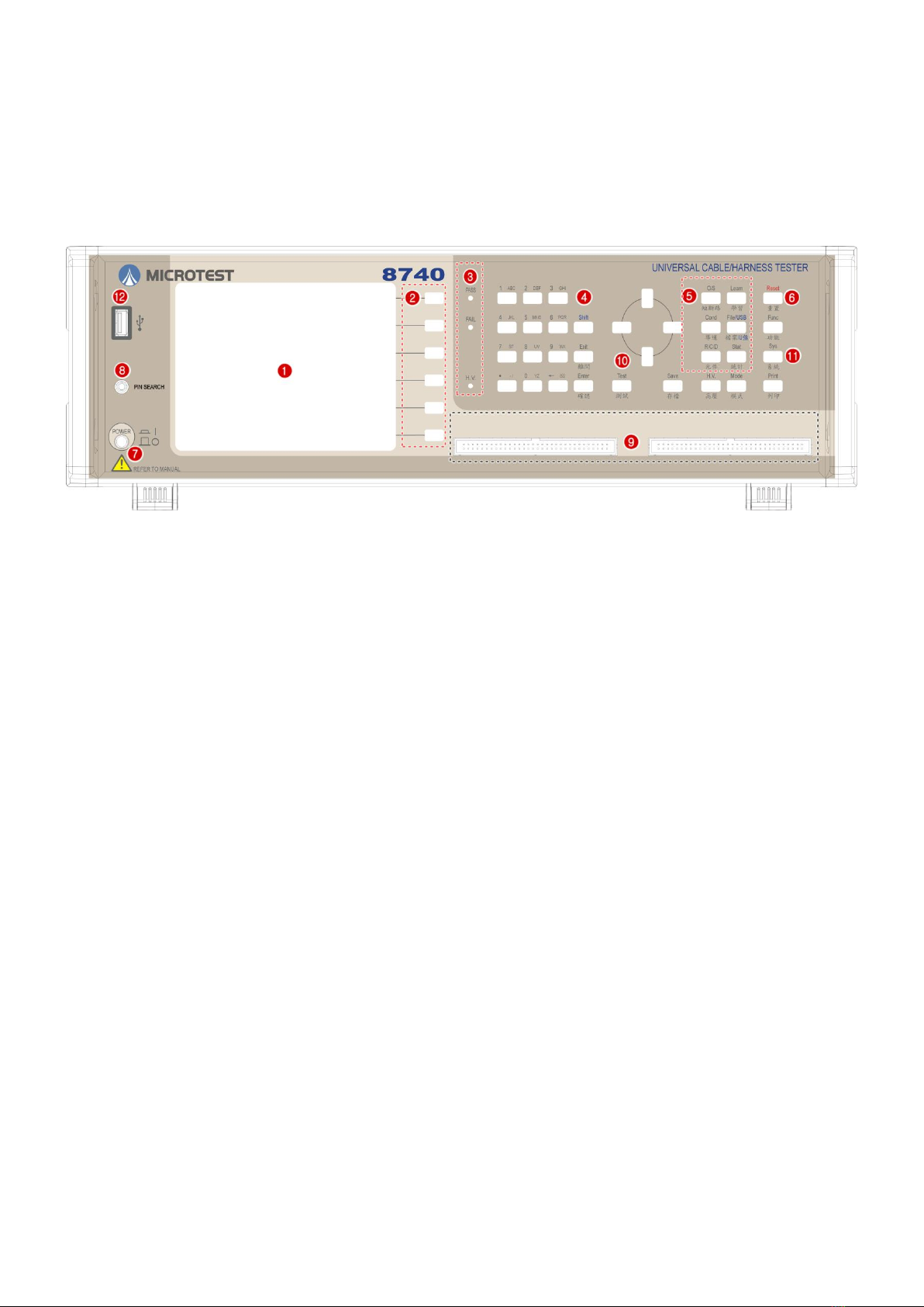
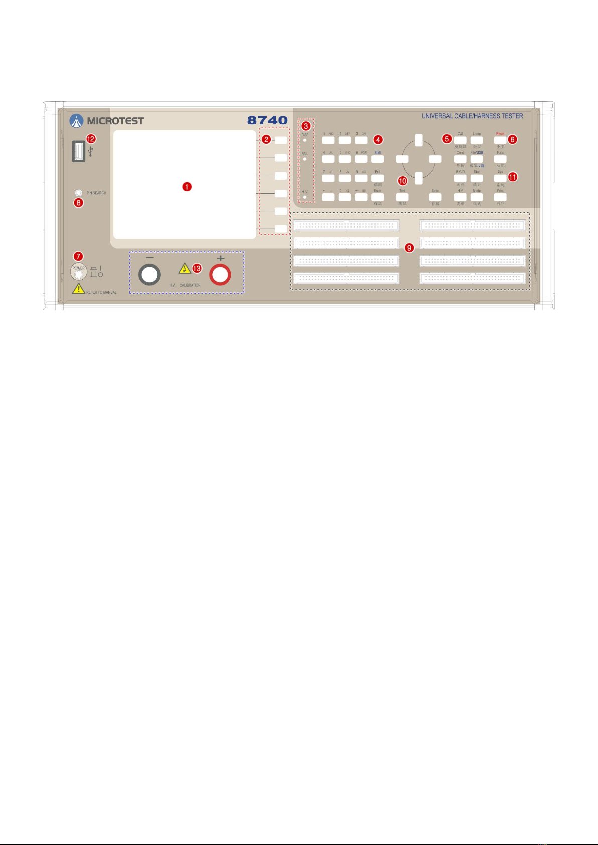
2.4.1 Front Panel.....................................................................................................................7
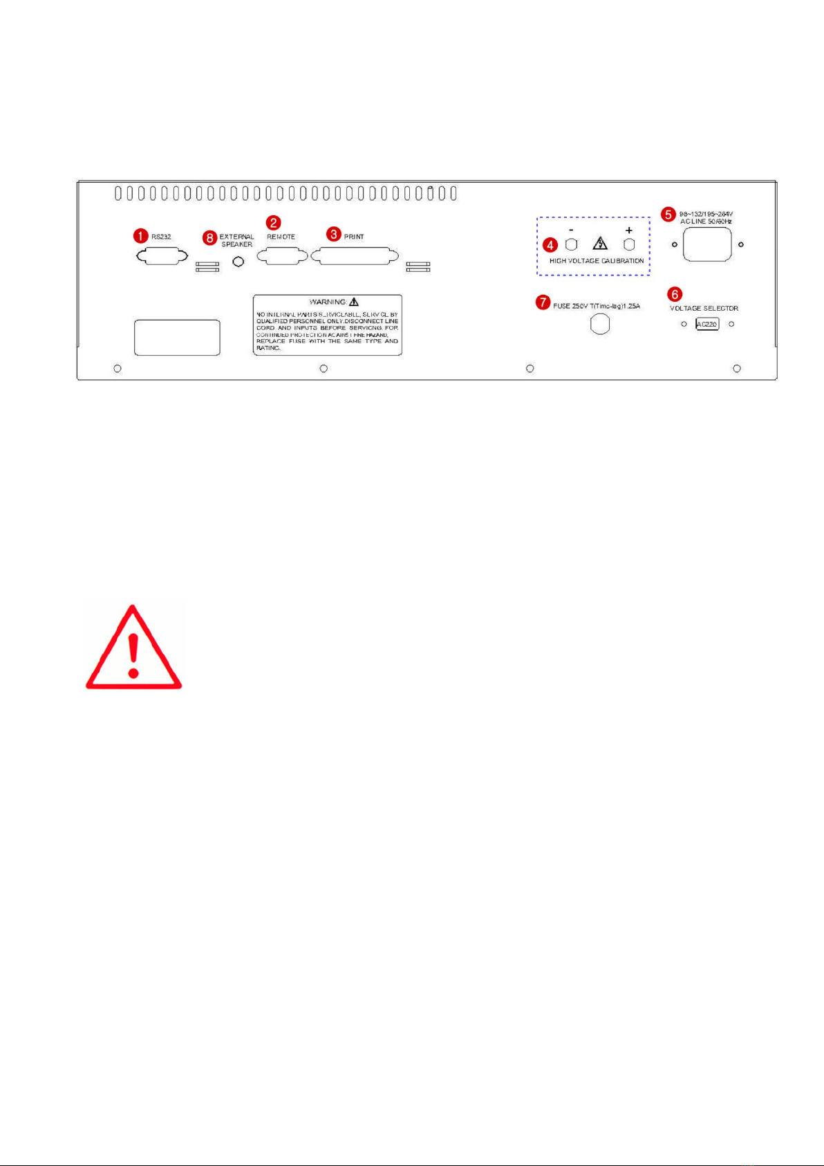
2.4.2 Rear panel......................................................................................................................9
2.5 Function Block Diagram..........................................................................................................11
2.6 Installation ...............................................................................................................................12
2.7 Button Instructions...................................................................................................................14
Chapter 3. Function setting and System setting.................................................................................16
3.1 Function...................................................................................................................................16
3.1.1 Self-test........................................................................................................................17
3.1.2 System Info..................................................................................................................17
3.1.3 Calibration ...................................................................................................................18
3.1.4 Pin Search....................................................................................................................22
3.1.5 Ethernet Fixture Setting (Ethernet Fix.) ......................................................................23
3.2 System Setup (SYS) ................................................................................................................24
3.2.1 Setting the System Environment .................................................................................24
3.2.2 Setting the Test Environment.......................................................................................27
3.2.3 Setting the System Time ..............................................................................................32
3.2.4 Changing the System Password...................................................................................33
3.3 Print..........................................................................................................................................34
3.4 Learn........................................................................................................................................34
3.5 File...........................................................................................................................................34

2
3.6 Statistic ....................................................................................................................................35
3.7 Mode........................................................................................................................................36
3.7.1 MultDut........................................................................................................................44
3.7.2 Item..............................................................................................................................45
Chapter 4. Comprehensive Test mode.................................................................................................46
4.1 Test Condition Setting .............................................................................................................46
4.1.1 Test Condition Setting Short Circuit Table (OPEN/SHORT)......................................46
4.1.2 Conductance ................................................................................................................47
4.1.3 R/C/D Component Setting Edit (Resistance) ..............................................................49
4.1.4 High Voltage Setting Edit (HV)...................................................................................53
4.2 Comprehensive Test Implementation ......................................................................................59
4.2.1 Real-time Test..............................................................................................................59
4.2.2 Existed Test..................................................................................................................60
4.3 File Management .....................................................................................................................61
4.3.1 Select File ....................................................................................................................61
4.3.2 Step Setting..................................................................................................................62
4.3.3 Create New File...........................................................................................................67
4.3.4 Upload File ..................................................................................................................67
4.3.5 Upload All....................................................................................................................68
4.3.6 Delete File....................................................................................................................68
4.3.7 Sort File .......................................................................................................................69
4.3.8 Import File ...................................................................................................................70
APPENDIX A Cable Wiring Configuration............................................................................................71
APPENDIX B Test Range and Functions................................................................................................74
APPENDIX C Technical specifications....................................................................................................75
APPENDIX D Version...............................................................................................................................76
Microtest Corporation all rights reserved.
Declaration: Microtest Corporation reserves the right to modify the
contents of this manual without further notice!

3
Chapter 1. Precautions
This instrument is not suitable for outdoor use, especially in humid or highly dusty locations. Improper use
of this instrument may result in electric shocks. Please read the safety descriptions carefully before using
this tester in order to avoid improper or wrong use causing accidents.
1.1 Safety Signs
The following safety signs may appear in this manual and on this instrument.
: Note, please read this manual carefully for these contents.
: Protective ground terminal: Please ground this terminal properly before using this tester in
order to avoid electrical shock accidents from coming in contact with the case with power leakages.
: Warning Sign: When the product is used improperly, it may cause improper results to this
instrument or other DUT.
: Warning Sign: When the product is used improperly, it may cause injuries or even death.
1.2 Do not modify or make internal adjustments to this machine
Without authorization from our company, do not install replacement components or perform any
modifications or adjustments to this machine on your own in order to avoid increasing the danger of the
machine or causing damages to the machine.
1.3 Static Electricity
Do not allow objects with static electricity come in contact with this machine in order to prevent damages
to the machine.
1.4 Ground
There is a ground terminal inside the power socket of this tester. Please ground this terminal properly in
order to prevent electrical shock accidents from occurring when touching the case.
1.5 Power
Power cables that comply with the local country specifications must be used, and connectors applicable to
IEC320 connectors must be used for the connection of this instrument. Users must ensure that the ground
cable is properly grounded. If a fuse is included in the power plug, use fuses that comply with T(Time-
lag)1.25 ampere safety regulations, and ensure that it is AC power supply with a voltage between 98V-
132V/195V-264V @50/60Hz.
1.6 Warm Up
The tester can operate normally once the power is turned on; however, in order to achieve the accuracy
within specification, please turn on the machine in advance and let it warm up for 30 minutes before use.

4
1.7 Machine Malfunction
When the instrument malfunctions, please send the machine back to the original manufacturer to have
professionals repair it for you in order to ensure the accuracy and operation safety of the meter.
1.8 Test End
Please switch the machine power off when the machine is not used for an extended amount of time.
1.9 Placement and Storage
The operating temperature and humidity range of this machine is 18 oC - 28 oC, 80% RH; the error in
measurement data will be greater if this range is exceeded. The storage temperature and humidity range of
this machine is -20 oC - 70 oC, 80% RH. In order to achieve accurate testing and for safety considerations,
do not place this machine in environments with direct sunlight exposure, high temperature, high humidity,
frequent vibrations, excessive dust, or unable power grid.
1.10 Emergency Handling
When there is an electric shock or if the DUT or machine catches on fire, please switch off the power and
unplug the power cable.

5
Chapter 2. General description
2.1 Package and Accessories
Standard accessories included in the 8740 series cable tester package should include the following items:
1 x 8740 cable tester
2 x moving needle type boxed connector
1 x automatic pin search probe
1 x power cable and power cable connector (3 pin to 2 pin)
1 x user manual
2.2 Description of Nouns and Symbols Used in This Manual
[xxxx] represents the name of buttons on the tester; for example [TEST].
[Sy[xxxx] This represents the buttons displayed on the LCD; y is the SoftKey number (1-6) and xxxx
is the button name, for example: S1[PROG].
{xxxxxxxx} represents the text message displayed on the LCD.
|xxxx| This represents the switching option name on the LCD; for example |ON|
<Pxx>This represents related reference page; for example <P21>
(xxxx) English Description

6
2.3 Basic Operations of the Tester
Alphanumeric input Alphanumeric characters need to be inputted when saving files; the design used
for this system is EditKey. The first time it is pressed it will be the number; the
2nd-4th time will be the capital English letter from the left to the right on top of
the number buttons respectively; examples are as follows:
Button
name
Number of
times
pressed
LCD
display
1
1
1
1
1
1
2
1A
1
1A
1
3
1AB
Moving You can use [←][↑][→][↓] to move the cursor.
Confirm [Enter] is the general confirm button.
Test/Exit [TEST] is the start testing button and [Exit] is the exit button.

7
2.4 Front and Rear Panel Functions
2.4.1 Front Panel
128 and 256 models:
(1) LCD display
(2) S1-S6 operation auxiliary buttons (Soft Key)
(3) PASS & FAIL & HIPOT LED
(4) Control button (Edit Key) group
(5) Test shortcut button group
(6) System reset (Reset) button
(7) Power switch
(8) Pin search connector
(9) 128Pin has 2 slots and 256 Pin has 4 slots
(10) Test button [TEST]
(11) System button (Sys Key) group
(12) USB flash drive
○
2

8
512 model:
(1) LCD display
(2) S1-S6 operation auxiliary buttons (Soft Key)
(3) PASS & FAIL & HIPOT LED
(4) Control button (Edit Key) group
(5) Test shortcut button group
(6) System reset (Reset) button
(7) Power switch
(8) Pin search connector, 512Pin has 8 slots
(9) 512Pin has 8 slots
(10) Test button [TEST]
(11) System button (Sys Key) group
(12) USB flash drive
(13) High voltage correction output connector

9
2.4.2 Rear panel
128 Model:
(1) Serial port (RS-232 Port)
(2) Remote control port (Remote Port)
(3) Printer Port
(4) High voltage correction output connector
(5) AC power input (230/115 VAC)
(6) 115/230V switch
(7) Fuse Holder 250V/T1.25A.
(8) Audio output socket
Note:
1. Please confirm whether the AC input voltage setting is the same as the
voltage used.
2. The input power must be grounded when using the machine.

10
512 model:
(1) Serial port (RS-232 Port)
(2) Remote control port (Remote Port)
(3) Printer Port
(4) AC power input (230/115 VAC)
(5) 115/230V switch
(6) Fuse holder 250V/T1.25A.
(7) Audio output socket
Note:
1. Please confirm whether the AC input voltage setting is the same as the
voltage used.
2. The input power must be grounded when using the machine.

11
2.5 Function Block Diagram
Main screen
[Mode]
[TEST]
Test mode setting
Comprehe
nsive test
[Func] Mode
Function setting
Conduction
setting
Test
Yes/No
[Setup] Mode
System Settings
DC insulation
setting
Test
AC tolerance
setting
Yes/No
[Stat]
Statistical data
R setting
Test
Yes/No
[Print]
Print setting
C setting
Test
Yes/No
[TEST]
Comprehensive
test
Diode setting
Test
Yes/No
[File]
File
Management
O/S setting
Test
Yes/No

12
2.6 Installation
(1) Please confirm the power of the power supply and that the power source connected is AC115V or
230V.
(2) Connect the connector and test cable according to usage needs.
(3) Turn on the power; the system will execute the self-test program.
(4) When the execution of the self-test is completed, it will officially enter the 8740 system; the LCD
display will be as follows:
(5) To end the system, please press the [Power switch] to end.
Note:
1. Self-test will be executed after powering on, which will take
approximately 60-80 seconds.
2. Under the {READY} status, the operation auxiliary buttons S1-S6 will
have the following adjustment functions.

13
S1
Makes the backlight of the LCD brighter
S2
Makes the backlight of the LCD darker
S3
Increases the volume level
S4
Decreases the volume level
S5
Software version and update date display
S6
Switch between Chinese/English
1
Quickly switches to the short circuit table function (same as [O/S])
2
Quickly switches to the learning function (same as [Learn])
3
Quickly switches to file manager (same as [File])
4
Quickly switches to conductance edit function (same as [Cond])
5
Quickly switches to the component edit function (same as [R/C/D])
6
Quickly Switch to the Statistics Function (Same as [Stat])

14
2.7 Button Instructions
【1】System (Sys Key) button group
[Func] System function menu
[Sys] System setting menu
[Print] Print function menu
【2】Test shortcut (Fast Key) button group
[File] File manager setting
[Learn] Short circuit learning
[Stat] Display test statistics data
[Mode] Test mode setting
[O/S] Short circuit table display
[Cond] Conductance test edit
[Stat] Statistics Function
[R] Resistance setting edit
[C] Capacitor setting edit
[D] Diode setting edit
[H.V.] DC insulation/AC tolerance setting edit
【3】Control button (Edit Key) group
Alphanumeric buttons Used to enter alphanumeric characters, including 0-1, A-Z and . /
[BS] () Back space
Direction buttons Used to move the cursor; includes [←] [→] [↑] [↓]
[PgUp] [PgDn] makes it easier to edit data.
[Exit] Makes the system exit the current status and return to the previous status.

15
【4】[Enter] Confirm button
【5】[TEST] Start test button
【6】Operation Auxiliary Button (Soft Key) Group
S1-S6 are located to the right of the LCD; they are used for auxiliary operations/settings.
【7】[Reset] System reset button, which works the same as warm start
【8】[Save] Save file button
【9】[Shift] Switch button function button

16
Chapter 3. Function setting and System setting
The function settings and analysis modes include main system functions [Func], system settings [Setup]
and print function [Print]; descriptions are as follows:
3.1 Function
Provides the main function for the system; its operations and function descriptions are as follows:
(1) Press [Func].
(2) The LCD screen will display as follows:
(3) Please use the [↑] or [↓] buttons to select the item needed.
(4) Press [Enter] to enter the selected item function.
(5) Press [Exit] to return to the previous screen.

17
3.1.1 Self-test
This function allows the setting for whether this machine will execute the self-test function immediately
upon powering on.
(1) Press [Func]; please use [↑] or [↓] to select Self-Test and then press [Enter].
(2) The system will now execute the self-test function.
(3) The LCD screen will display as follows:
(4) Press [Exit] to exit
3.1.2 System Info.
This item allows for the viewing of the 8740 machine and version information; it lists the machine’s model
number, test pins, total space used by files, and the total remaining space, etc. And it can perform system
update.
(1) Press [Func]; please use [↑] or [↓] to select System Info and then press [Enter].
(2) The LCD screen will display as follows:

18
3.1.3 Calibration
This function includes [1] DC H.V.CAL, [2] AC H.V. CAL [3] AC H.V. CAL [4] Curr.Fix.CAL.
(1) Press [Func].
(2) Please use [↑] or [↓] to select Calibration and then press [Enter].
(3) The LCD screen will display as follows:
(4) Press [Exit] to exit.
DC H.V.CAL
The DC high voltage correction is used to adjust the READING (test value) closest to the DC setting
value.
(1) Press [Func].
(2) Please use [↑] or [↓] to select Calibration and then select DC H.V. CAL. and press [Enter].
(3) The LCD screen will display as follows:
(4) Press S1 [UP] or S2 [DOWN] to adjust the READING (test value) closest to the DC setting value.
Or S5 for automatic adjustment.
(5) When setting is complete, please press S4 [OK].
(6) To cancel the set data, simply press S6 [QUIT].

19
AC H.V. CAL
The AC high voltage correction is used to adjust the READING (test value) closest to the AC setting
value.
(1) Press [Func].
(2) Please use [↑] or [↓] to select Calibration and then select AC H.V. CAL. and press [Enter].
(3) The LCD screen will display as follows:
(4) Press S1 [UP] or S2 [DOWN] to adjust the READING (test value) closest to the DC setting value.
Or S5 for automatic adjustment.
(5) When setting is complete, please press S4 [OK].
(6) To cancel the set data, simply press S6 [QUIT].
This manual suits for next models
3
Table of contents
Other Microtest Cable Tester manuals