Microtest 8751 User manual

8751/8761
4-Wire Universal Cable/Harness Tester
User Manual
Version: 1.00
Issued Date: May, 2017

1
Table of Contents
Chapter 1 Cautions......................................................................................................................................3
1.1 Safety Symbols................................................................................................................................3
1.2 Avoid Self-Modification or Calibration...........................................................................................3
1.3 Static Electricity...............................................................................................................................3
1.4 Ground.............................................................................................................................................3
1.5 Power Supply...................................................................................................................................3
1.6 Warming-Start..................................................................................................................................4
1.7 Device Malfunctions........................................................................................................................4
1.8 Unexpected Termination during Test Process..................................................................................4
1.9 Location and Storage.......................................................................................................................4
1.10 Troubleshooting for Urgent Conditions.........................................................................................4
Chapter 2 General Summary .....................................................................................................................5
2.1 Package and Accessories .................................................................................................................5
2.2 Description of Nouns and Symbols Used in this Manual................................................................5
2.3 Operating Basics..............................................................................................................................6
2.4 Front and Rear Panel Displays ........................................................................................................7
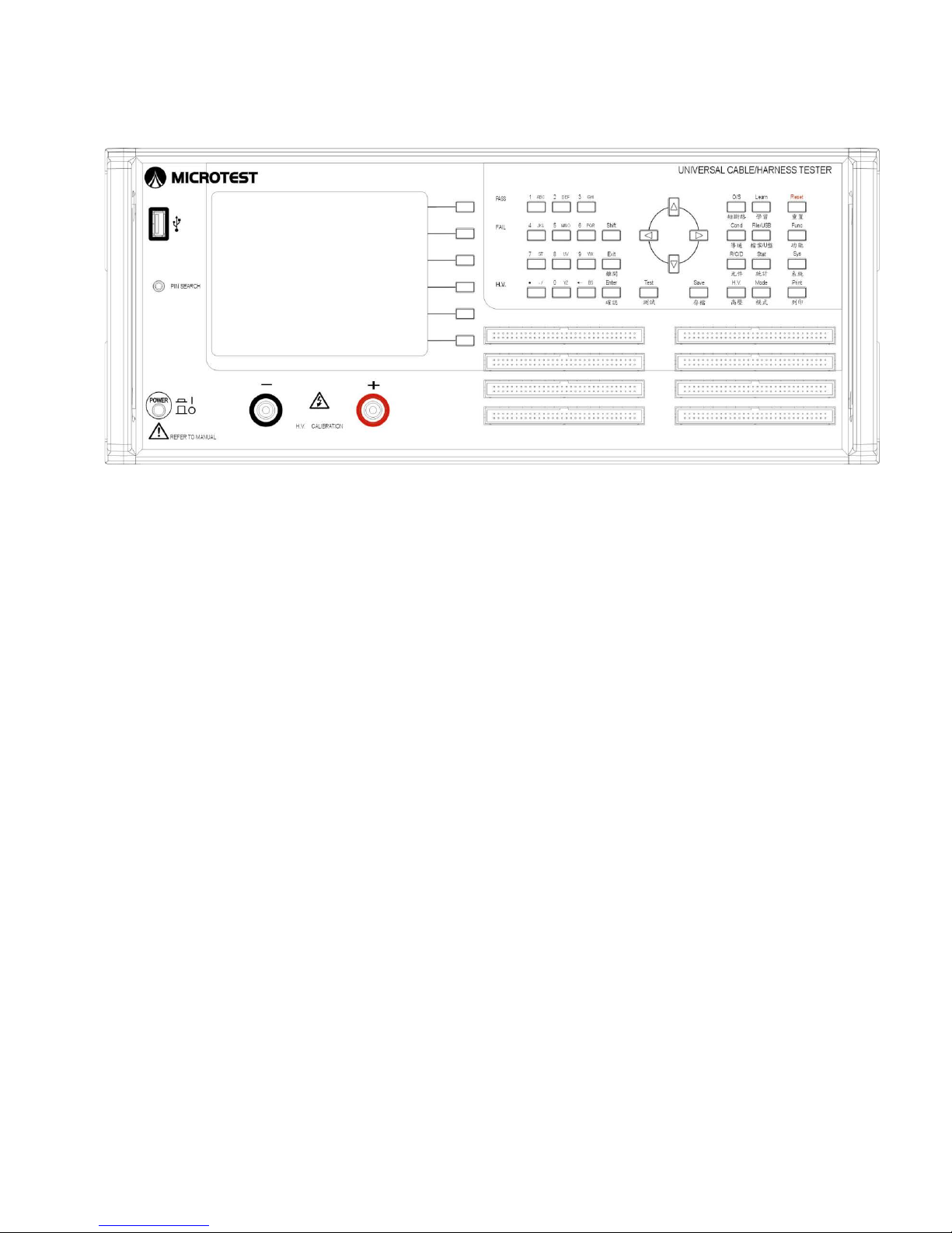
2.4.1 Front Panel............................................................................................................................7
2.4.2 Rear Panel.............................................................................................................................9
2.5 Block Diagram of Tester Functions...............................................................................................11
2.6 Installation .....................................................................................................................................12
2.7 Button Usage Instructions..............................................................................................................14
Chapter 3 Function Setting and System Setting.....................................................................................15
3.1 Function Menu...............................................................................................................................15
3.1.1 System Self-Test .................................................................................................................16
3.1.2 RAM Configuration Table..................................................................................................17
3.1.3 Test Parameter Calibration..................................................................................................17
3.1.4 Pin Search...........................................................................................................................21
3.1.5 Meter Mode ........................................................................................................................22
3.1.6 Networking Fixture Setting ................................................................................................26
3.2 System Setting (SYS)....................................................................................................................27
3.2.1 Setting the Operating Environment ....................................................................................28
3.2.2 Setting the Testing Environment.........................................................................................30
3.2.3 Set System Time.................................................................................................................33
3.2.4 Change System Password...................................................................................................34

2
3.3 Print Function Menu......................................................................................................................35
3.4 Learning Short Circuit Setting and Edit ........................................................................................35
3.5 File Management (File) .................................................................................................................38
3.6 Statistical Data (Statistic) ..............................................................................................................38
3.7 Mode Setting (Mode).....................................................................................................................39
3.7.1 Multiple Simultaneous Test DUT (MiltiDut) .....................................................................48
3.7.2 Test Item (Item) ..................................................................................................................50
Chapter 4 Comprehensive Test Mode......................................................................................................50
4.1 Test Condition Setting ...................................................................................................................51
4.1.1 Test Condition Setting O/S NET (OPEN/SHORT) ............................................................51
4.1.2 Conductance Test Edit (Conductance)................................................................................51
4.1.3 R/C/D Component Setting Edit (Resistance) .....................................................................54
4.1.4 High Voltage Setting Edit (HV)..........................................................................................58
4.2 Comprehensive Test Implementation ............................................................................................62
4.2.1 Real Time Test ....................................................................................................................62
4.2.2 Existed Test.........................................................................................................................62
4.3 File Management ...........................................................................................................................63
4.3.1 Select File ...........................................................................................................................63
4.3.2 Step Setting.........................................................................................................................64
4.3.3 Create New File..................................................................................................................70
4.3.4 Upload File .........................................................................................................................70
4.3.5 Upload All...........................................................................................................................71
4.3.6 Delete File...........................................................................................................................71
4.3.7 File Sorting .........................................................................................................................72
4.3.8 Import File ..........................................................................................................................74
APPENDIX A Cable Wiring Configuration............................................................................................76
APPENDIX B Test Range and Functions................................................................................................79
APPENDIX C Technical Specifications...................................................................................................80
APPENDIX D Version...............................................................................................................................81
Microtest Corporation all rights reserved.
Declaration: Microtest Corporation reserves the right to modify the contents of this manual
without further notice!

3
Chapter 1 Cautions
Do not use this instrument outside and avoid humid or dusty areas. Use of this instrument in an improper
setting can increase the risk of electrical shock. Carefully read all safety instructions before using the
device to prevent accidents due to misuse.
1.1 Safety Symbols
The following safety symbols may appear in this user manual and on the device itself.
Caution: Carefully read the user manual for detailed information.
Earthing Required: Check that this terminal is earthed before operating the device to
prevent electrical shocks due to leakage or contact with the housing.
: Improper use of the device may result in instrument or testing DUT malfunctions.
: Improper use of the device may result in injury or death.
1.2 Avoid Self-Modification or Calibration
Never install surrogate parts onto the machine or undertake any device modifications and internal
calibrations yourself without the express permission of Microtest, as you may increase the levels of
danger associated with the device or damage the device.
1.3 Static Electricity
Keep items bearing static electricity away from the device to prevent damage.
1.4 Ground
A safe ground terminal is located on the outer housing of the back panel of the device; check that
this terminal is properly grounded to prevent contact with the housing and risk of electrical shock.
1.5 Power Supply
You must use a power supply cable that meets local national specifications and an
IEC320-compatible connector to connect the cable to the instrument. The user must check that the
earth wire is properly earthed. If a fuse is included in the power supply plug it must be a 3.15A fuse

4
compatible with relevant safety regulations. Always check before use to ensure A/C power supply
and voltage values are between 100V-240V @ 50/60Hz.
1.6 Warming-Start
The testing device can be used normally immediately after switching the power on, but will not
meet accuracy specifications unless allowed to warm up for 30 minutes.
1.7 Device Malfunctions
Return all malfunctioning instruments to the manufacturer for professional repair in order to ensure
the accuracy and operational safety of the instrument.
1.8 Unexpected Termination during Test Process
Please turn the device off at the power source if it will not be used for a long period of time.
1.9 Location and Storage
The device may be operated normally in temperatures of 18-28°C with up to 80% RH. The device
may not operate in conditions exceeding these limits. The device should be stored at -20°C~70°C
with up to 80% RH. In order to ensure testing accuracy and safety, avoid installing the device
anywhere it would be exposed to direct sunlight, extreme heat, extreme humidity, vibration
frequencies, dust, or unstable power grids.
1.10 Troubleshooting for Urgent Conditions
Switch off the power supply and disconnect the power supply cable in the event of electrical shock,
test item combustion and device combustion.

5
Chapter 2 General Summary
2.1 Package and Accessories
Standard accessories included in the 8751/8761 series tester package should include the following items:
1 x 8751 4-Wire Universal Cable/Harness Tester
2 x 64 moving needle type boxed connector (128P)
1 x automatic pin search probe
1 x power cable and power cable connector (3 pin to 2 pin)
1 x user manual
2.2 Description of Nouns and Symbols Used in this Manual
[xxxx] This represents the name of buttons on the tester; for example [TEST]
[Sy[xxxx] This represents the buttons displayed on the LCD; y is the SoftKey number (1~6),
and xxxx is the button name. For example S1[PROG]
{xxxxxxxx} This represents the text messages displayed on the LCD
|xxxx| This represents the switching option name on the LCD; for example |ON|
<Pxx> This represents related reference page; for example <P21>
(xxxx) English description

6
2.3 Operating Basics
Alphanumeric input Alphanumeric characters need to be inputted when saving files; the design
used for this system is EditKey. The first time it is pressed, it will be numbers,
and the 2nd~4th time will be the capital English letter from the left to the right
on top of the number buttons respectively; examples are as follows:
Button name Number of times pressed LCD display
1
1
1
1
1
1 2 1A
1 1A
1
3
1AB
Moving You can use [←][↑][→][↓] to move the cursor
Confirm [Enter] is the general confirm button
Test/Exit [TEST] is the start testing button, and [Exit] is the exit button

7
2.4 Front and Rear Panel Displays
2.4.1 Front Panel
64 and 128 models:
(1) LCD display
(2) S1~S6 operation auxiliary buttons (Soft Key)
(3) PASS & FAIL & HIPOT LED
(4) Control button (Edit Key) group
(5) Test shortcut button group
(6) System reset (Reset) button
(7) Power switch
(8) Pin Search connector
(9) 128Pin has 2 slots and 256 Pin has 4 slots
(10) Test button [TEST]
(11) System button (Sys Key) group
(12) USB flash drive
○
1
○
2 ○
3 ○
4 ○
5 ○
6
○
7
○
8
○
9
○
10
○
11
○
12

8
256 model:
(1) LCD display
(2) S1~S6 operation auxiliary buttons (Soft Key)
(3) PASS & FAIL & HIPOT LED
(4) Control button (Edit Key) group
(5) Test shortcut button group
(6) System reset (Reset) button
(7) Power switch
(8) Pin Search connector
(9) 256Pin has 8 slots
(10) Test button [TEST]
(11) System button (Sys Key) group
(12) USB flash drive
(13) High voltage calibration output connector
○
1
○
2
○
3
○
4
○
5 ○
6
○
7
○
8
○
9
○
10 ○
11
○
12
○
13

9
2.4.2 Rear Panel
128 model:
(1) Serial port (RS-232 Port)
(2) Remote control port (Remote Port)
(3) Printer Port
(4) High voltage calibration output connector
(5) AC power input (230/115 VAC)
(6) 115/230V switch
(7) Fuse holder 250V/3A
(8) Audio output socket
Note:
1. Please confirm whether the AC input voltage setting is the same as the
voltage used.
2. The input power must be grounded when using the machine.
○
1 ○
2 ○
3 ○
4 ○
5
○
6
○
7
○
8

10
256 model:
(1) Serial port (RS-232 Port)
(2) Remote control port (Remote Port)
(3) Printer Port
(4) AC power input (230/115 VAC)
(5) 115/230V switch
(6) Fuse holder 250V/3A
(7) Audio output socket
Note:
1. Please confirm whether the AC input voltage setting is the same as the
voltage used.
2. The input power must be grounded when using the machine.
○
1 ○
2 ○
3 ○
4
○
5
○
6
○
7

11
2.5 Block Diagram of Tester Functions
Main screen
[Mode]
[TEST]
Test mode setting
Comprehensive
test
[Func] Mode
Function setting
Conduction
setting
Test
Yes/No
[Setup] Mode
System setting
DC insulation
setting
Test
AC tolerance
setting
Yes/No
[Stat]
Statistical data
R setting
Test
Yes/No
[Print]
Print setting
C setting
Test
Yes/No
[TEST]
Comprehensive
test
Diode setting
Test
Yes/No
[File]
File
management
O/S setting
Test
Yes/No

12
2.6 Installation
(1) Please confirm the power of the power supply and that the power source connected is AC 115V or
230V.
(2) Connect the connector and test cable according to usage needs.
(3) Turn on the power; the system will execute the self-test program.
(4) When the execution of the self-test is completed, it will officially enter the 8751/8761 system; the
LCD display will be as follows:
(5) To end the system, please press the [Power switch] to end.
Note:
1. Self-test will be executed after powering on, which will take approximately
60~80 seconds.
2. Under the {READY} status, the operation auxiliary buttons S1~S6 will
have the following adjustment functions.

13
Power on screen shortcut buttons:
S1 Makes the backlight of the LCD brighter
S2 Makes the backlight of the LCD darker
S3 Increases the volume level
S4 Decreases the volume level
S5 Software version and update date display
S6 Switch between Chinese/English
1 Quickly switches to the short circuit table function (same as [O/S])
2 Quickly switches to the learning function (same as [Learn])
3 Quickly switches to file manager (same as [File])
4 Quickly switches to conductance edit function (same as [Cond])
5 Quickly switches to the component edit function (same as [R/C/D])

14
2.7 Button Usage Instructions
【
1
】
System (Sys Key) button group
[Func] System function menu
[Sys] System setting menu
[Print] Print function menu
【
2
】
Test shortcut (Fast Key) button group
[File] File manager setting
[Learn] Short circuit learning
[Stat] Display test statistics data
[Mode] Test mode setting
[O/S] Short circuit table display
[Cond] Conductance test edit
[R] Resistance setting edit
[C] Capacitor setting edit
[D] Diode setting edit
[H.V.] DC insulation/AC tolerance setting edit
【
3
】
Control button (Edit Key) group
Alphanumeric buttons Used to enter alphanumeric characters, including 0~1, A~Z and ./
[BS] () Back Space
Direction buttons Used to move the cursor; includes [←] [→] [↑] [↓]
[PgUp] [PgDn] makes it easier to edit data
[Exit] Makes the system exit the current status and return to the previous
status
【
4
】
[Enter] Confirm button
【
5
】
[TEST] Start test button
【
6
】
Operation auxiliary button (Soft Key) group, S1~S6 are located to the right of the LCD, which
are used for auxiliary operation/setting
【
7
】
[Reset] System reset button, which works the same as warm start
【
8
】
[Save] Save file button
【
9
】
[Shift] Switch button function button

15
Chapter 3 Function Setting and System
Setting
The function settings and analysis modes include main system functions [Func], system settings [Setup]
and print function [Print]; descriptions are as follows:
3.1 Function Menu
Provides the main function menu for the system; its operations and function descriptions are as follows:
(1) Press [Func].
(2) The LCD screen will display as follows:
(3) Please use the [↑] or [↓] buttons to select the item needed.
(4) Press [Enter] to enter the selected item function.
(5) Press [Exit] to return to the previous screen.

16
3.1.1 System Self-Test
This function allows the setting for whether this machine will execute the self-test function immediately
upon powering on.
(1) Press [Func]; please use [↑] or [↓] to select system self-test and then press [Enter].
(2) The system will now execute the self-test function.
(3) The LCD screen will display as follows:
(4) Press [Exit] to exit.

17
3.1.2 RAM Configuration Table
This item allows the viewing of the 8751/8761 machine and version information; it lists the machine’s
model number, test pins, total space used by files and the total remaining space etc. And it can perform
system update.
(1) Press [Func]; please use [↑] or [↓] to select RAM configuration table and then press [Enter].
(2) The LCD screen will display as follows:
3.1.3 Test Parameter Calibration
This function includes DC high voltage calibration, AC high voltage calibration and internal resistance
offset.
(1) Press [Func].
(2) Please use [↑] or [↓] to select test parameter calibration and then press [Enter].
(3) The LCD screen will display as follows:

18
(4) Press [Exit] to exit.
DC High Voltage Calibration
The DC high voltage calibration is used to adjust the Read (test value) closest to the DC setting value.
(1) Press [Func].
(2) Please use [↑] or [↓] to select test parameter calibration and then select DC high voltage calibration
and press [Enter].
(3) The LCD screen will display as follows:

19
(4) Press S1 [increase] or S2 [decrease] to adjust the Read (test value) closest to the DC setting value.
Or S5 for automatic adjustment.
(5) When setting is complete, please press S4 [Save].
(6) To cancel the set data, simply press S6 [Cancel].
AC High Voltage Calibration
The AC high voltage calibration is used to adjust the Read (test value) closest to the AC setting value.
(1) Press [Func].
(2) Please use [↑] or [↓] to select test parameter calibration, then select AC high voltage calibration and
press [Enter].
(3) The LCD screen will display as follows:
(4) Press S1 [UP] or S2 [DOWN] to adjust the Read (test value) closest to the AC setting value. Or S5
for automatic adjustment.
(5) When setting is complete, please press S4 [Save].
(6) To cancel the set data, simply press S6 [QUIT].
Internal Conductance Offset
This function can execute the internal resistance offset action of the machine.
(1) Press [Func].
(2) Please use [↑] or [↓] to select test parameter calibration, then select internal resistance offset and
This manual suits for next models
1
Table of contents
Other Microtest Cable Tester manuals