Midland ALAN 199-A User manual

MANUALE D’USO - USER’S MANUAL - MANUEL D’UTILISATION
BEDIENUNGSANLEITUNG - MANUAL DEL USUARIO
ALAN 199-A
®
®
cop 199 a 3 12 2002 14:21 Pagina 1

• SCHEMA BLOCCHI • BLOCK DIAGRAM • SCHÈMA A BLOCS • BLOCKSCHALFBILD • DIAGRAMA DE BLOQUES
cop 199 a 3 12 2002 14:21 Pagina 2

1
ITALIANO
INDICE
Principali funzioni ............................................................................2
Comandi ..........................................................................................2
Installazione ....................................................................................3
Sostituzione del fusibile ..................................................................4
Connessione del microfono ............................................................4
Montaggio dell'antenna ..................................................................4
Antenna base ..................................................................................5
Uso del ricetrasmettitore ................................................................6
Canali prioritari (CH 9-19) ..............................................................6
Altoparlante supplementare ............................................................6
Caratteristiche tecniche ..................................................................7
ALAN 199-A è un nuovo ricetrasmettitore veicolare, di dimensioni
ridotte, che opera in modalità AM. Di facile ed immediato utilizzo,
ALAN 199-A dà la possibilità di selezionare la potenza di uscita e
quindi può essere utilizzato in tutti quei paesi europei che consento-
no la normativa AM, nel rispetto della EN 300-433.
ISTR.199-A 3-12-2002 14:24 Pagina 1

PRINCIPALI FUNZIONI
• Il PLL permette un controllo preciso delle frequenze e maggior stabilità su tutti i
40 canali, con controlli separati di scansione verso l’alto e verso il basso.
• I filtri ceramici proteggono dalle interferenze dei canali adiacenti.
• Display con visualizzazione canali
• Commutatore 4W/1W per selezionare la potenza di emissione.
• Il LED rosso (TX) e il verde (RX), indicano la modalità operativa: RX= ricezione;
TX= trasmissione.
• La regolazione del circuito squelch permette di eliminare i fastidiosi rumori in
fase di ricezione.
• La presa esterna sul retro consente l’utilizzo di un eventuale altoparlante supple-
mentare.
• Il commutatore d’emergenza permette la commutazione immediata sul CH 9 o
CH 19.
• Connettore antenna SO239
COMANDI
2
ALAN 199-A 9
CH
19
40
TX
RX
4W 1W CHANNEL
SQUELCH ON/OFF VOL
SERIAL NO.
EXTANT
SPKR
+
-RED
BLK
Presa microfono Squelch Accensione
Volume
Connettore
antenna Cavo alimentazione
Presa altoparlante esterno
Commutatore
4W/1W
Commutatore canali
prioritari CH-9/19 Display
canali Led
RX/TX
Tasto cambio
canale
ISTR.199-A 3-12-2002 14:24 Pagina 2

INSTALLAZIONE
Ricercare e localizzare sul mezzo mobile, la posizione per l’installazione dell’appara-
to. Tale posizionamento deve essere fatto in modo da non creare intralcio a chi
guida, e nello stesso tempo, di facile accessibilità per poter togliere l’apparato
secondo le necessità.
La posizione di montaggio più comune è sotto il cruscotto (si sconsiglia vicino a
fonti di calore o vicino al condizionatore). Dopo aver stabilito la posizione più adat-
ta sul veicolo, mantenere il ricetrasmettitore con la staffa di montaggio nell’esatta
posizione desiderata e verificare che non ci siano inconvenienti; successivamente
segnare e forare il veicolo per il fissaggio delle viti di montaggio. Controllare che
esse siano ben ancorate, in considerazione delle notevoli sollecitazioni e vibrazioni
create dal mezzo mobile.
Collegare il filo rosso (con il fusibile) al positivo della batteria. Collegare il filo nero
al negativo della batteria (solitamente questo è il telaio dell’auto) tenendo conto che
una connessione corretta e stabile è indispensabile per il buon funzionamento del-
l’apparato. 3
ITALIANO
Rondelle
Rondelle
Rondelle
Rondelle
Viti
Viti
Vite
Staffa
Dadi
Dadi
Viti e rondelle
ANT EXT
SPKR
+RED
-BLK
ISTR.199-A 3-12-2002 14:24 Pagina 3

Per l’installazione in auto, la tensione a 13,8 Vcc è solitamente prelevabile dal con-
tatto ausiliario dell’interruttore d’accensione. Questo evita che l’apparato possa
rimanere acceso accidentalmente quando l’autista scende dall’auto e permette inol-
tre di poter operare senza che il motore sia in funzione. Prima di operare, installare
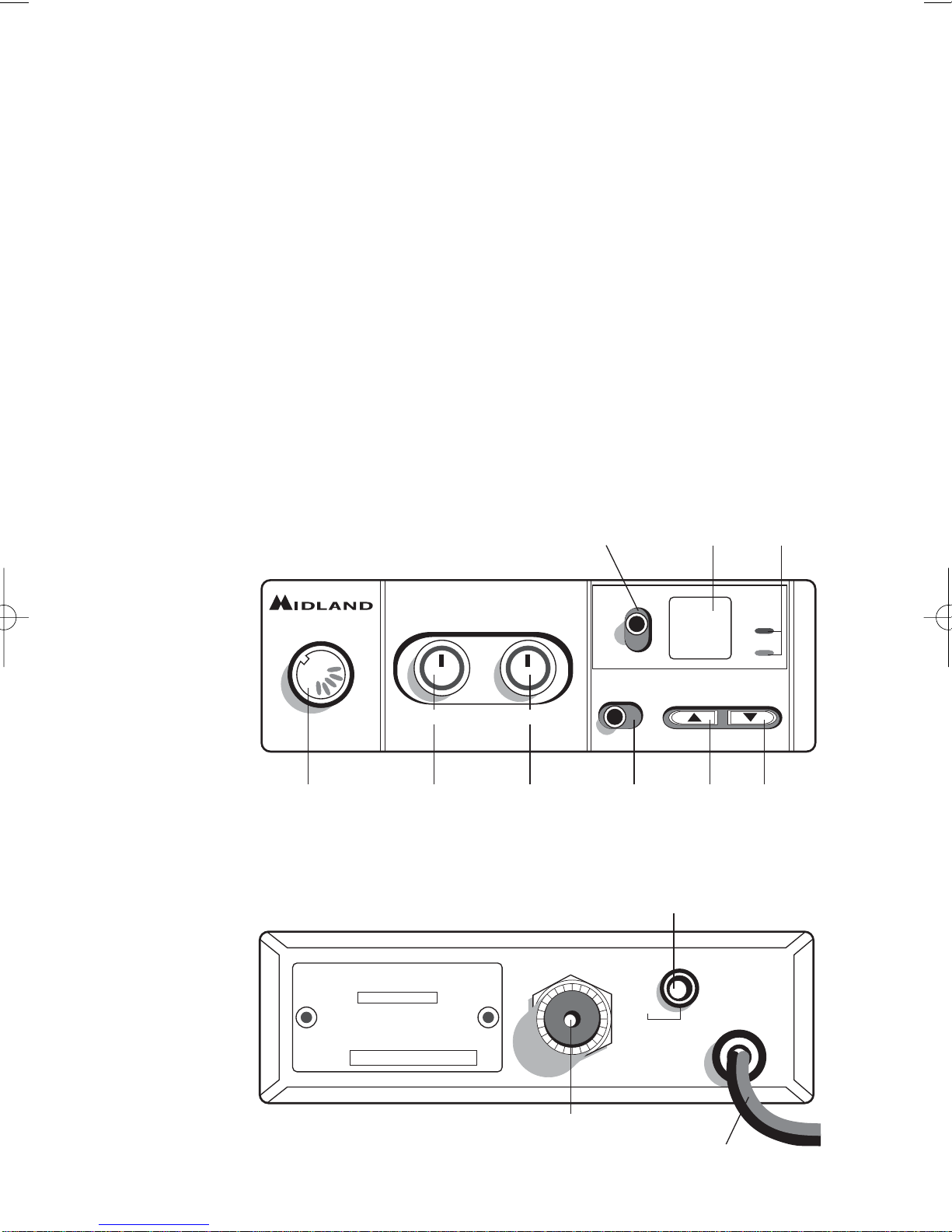
e collegare l’antenna inserendo il connettore nell'apposita presa sul retro dell’appa-
rato. Per l’uso di un altoparlante esterno, utilizzare la presa EXT-SPKR.
SOSTITUZIONE DEL FUSIBILE
Sostituire il fusibile del cavo di alimentazione con un similare a 2 A (Un fusibile di
ricambio è in dotazione).
CONNESSIONE DEL MICROFONO
La presa del microfono è situata sul davanti
dell’apparato. Premere il piccolo pulsante
sulla presa microfonica e inserire il microfo-
no. Per toglierlo, ripremere lo stesso pulsan-
te ed estrarre il microfono. Accertarsi sempre
che il connettore sia ben connesso alla presa.
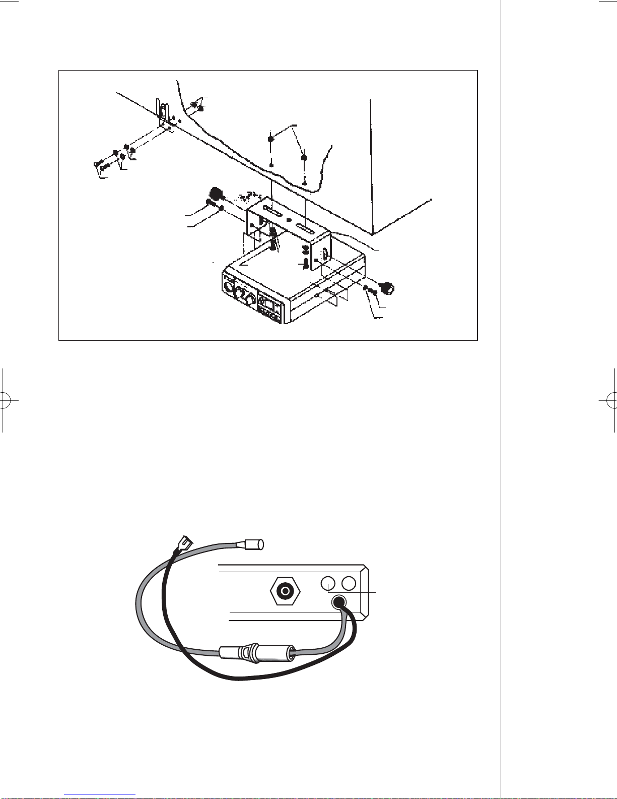
MONTAGGIO ANTENNA
L’antenna è l’elemento più importante per ottenere i migliori risultati. È indispensabile
che l’antenna abbia un’impedenza di 50 Ohm. A seconda della posizione in cui viene
installata, il rendimento varia notevolmente. Usare un cavo coassiale con impedenza 50
Ohm. Sono consigliati i cavi RG 58U per lunghezza sotto i 2.5 metri, oppure RG 8 per
lunghezze superiori. Il cavo coassiale deve essere montato con molta cura: evitare
curve e piegamenti. Inoltre va ricordato che il cavo più corto aumenta la sensibilità del-
l’apparato, così pure un cattivo collegamento tra apparato e antenna.
Consigli:
• Montare l’antenna nel posto più libero e più alto dell’auto.
• L’antenna deve essere installata in posizione verticale, e così deve rimanere anche
quando il veicolo è in moto.
• Montare l’antenna e il cavo il più possibile lontano da fonti di rumore.
• La massa dell’antenna deve coprire un’area di 1m2.
Esistono in commercio diversi tipi di antenna: con stilo a 1/4 d’onda; alimentate al cen-
tro; con carica in base; con carica in alto. Le antenne caricate sono più corte, ma per
un miglior rendimento si consigliano quelle di lunghezza di circa 2 metri.
L’installazione a centro tetto è la migliore in senso assoluto perché il ground o radiale
di terra è proporzionale in tutte le direzioni, mentre su una fiancata o in una qualsiasi
altra parte del veicolo, diventa proporzionale alla massa dello stesso (es: se l’antenna è
installata posteriormente, diventa direttiva in avanti, cioè i segnali provenienti dalla
4
ISTR.199-A 3-12-2002 14:24 Pagina 4

parte opposta sono meglio ricevuti, così dicasi anche per quelli trasmessi).
N.B.: con l’ausilio di un accoppiatore a due vie, l’antenna montata anteriormente può
sostituire l’antenna della radio FM.
Posizioni comuni di montaggio dell'antenna
ANTENNA BASE
Per l’utilizzo del ricetrasmettitore in stazione fissa (base) occorre un ali-
mentatore con una tensione di 12-13.8V capace di erogare una a cor-
rente continua di 2A. Si consiglia un’antenna 1/2 onda omnidirezionale
per comunicazioni a medio e lungo raggio.
5
ITALIANO
ISTR.199-A 3-12-2002 14:24 Pagina 5

USO DEL RICETRASMETTITORE
Ricezione:
1. Assicurarsi che il filo rosso sia connesso ad una tensione di 12-13.8 V.
2. Controllare che l’antenna e il microfono siano ben connessi.
3. Posizionare il commutatore d’emergenza sulla posizione centrale.
4. Scegliere la potenza di emissione con la quale si intende operare.
5. Girare la manopola squelch nella massima posizione antioraria.
6. Accendere l’apparato mediante la manopola VOLUME.
7. Ricercare il canale desiderato attraverso i tasti CHANNEL.
8. Regolare il volume come desiderato.
9. Regolare lo squelch. Questo comando viene utilizzato per eliminare il rumore di
fondo del ricevitore in assenza di segnali d’ingresso. Per la massima sensibilità
del ricevitore è preferibile che il comando sia regolato solo al preciso livello dove
il rumore di fondo del ricevitore o il rumore ambientale, viene eliminato. Girare
completamente in senso antiorario poi lentamente in senso orario finché non
scomparirà il rumore. Qualsiasi segnale affinché possa venir ricevuto, dovrà
essere leggermente più intenso rispetto alla media del rumore ricevuto. Un ulte-
riore rotazione in senso orario aumenterà il livello di soglia che il segnale dovrà
superare per poter essere udito. Se lo squelch sarà posizionato nella massima
posizione in senso orario, si potranno sentire solo segnali molto forti.
Trasmissione:
1. Selezionare il canale desiderato.
2. Premere il pulsante di trasmissione sul microfono, parlare mantenendo una
distanza dalle labbra dai 5 a 8 cm.
3. Per ricevere, rilasciare il pulsante di trasmissione.
N.B.: gridare nel microfono non aumenta la portata della trasmissione, in quanto un
circuito interno automaticamente commuta la massima modulazione. Si consiglia
quindi di usare un tono di voce normale.
CANALI PRIORITARI (CH 9-19)
L’ALAN 199-A è dotato di un commutatore che permette di posizionarsi immediata-
mente sui canali 9 e 19. Il canale 9 serve solo per le comunicazioni di emergenza. Il
canale 19 invece è usato per richiedere informazioni sulla viabilità, ecc.
Posizionando l’interruttore nella posizione centrale si ritornerà all’ultimo canale
selezionato.
ALTOPARLANTE SUPPLEMENTARE
Inserire un altoparlante con potenza da 3-10 W nella presa EXT-SPKR. In questo
modo l’altoparlante interno viene disconnesso.
6
ISTR.199-A 3-12-2002 14:24 Pagina 6

CARATTERISTICHE TECNICHE
RICEVITORE
Gamma di frequenza..................................................................da 26.965 a 27.405
Sensibilità..............................................................migliore di 1.0 µV per 20 dB S/N
Reiezione canali adiacenti......................................60 dB (10 KHz); 70 dB (20 KHz)
Frequenze IF........................................................1° IF=10.695 MHz; 2° IF=455 KHz
Potenza d’uscita audio ............................................................................4.5 W max
Risposta in frequenza ..................................................................6 dB:450-2500 Hz
Modulazione incrociata ..........................................................................45 dB o più
Squelch..........................................................................regolabile da 1.2 µV a 1mV
TRASMETTITORE
Gamma di frequenza..................................................................da 26.965 a 27.405
Potenza d’uscita........................................................................................4 W / 1 W
Modulazione........................................................................................................AM
Modulazione massima ......................................................................................90%
Emissioni spurie ....................................................................................62 dB o più
Tolleranza di frequenza ......................................................................più di 0.002%
Alimentazione ................................................................................................13.8 V
Corrente assorbita max ......................................................................................2 A
Impedenza antenna......................................................................................50 Ohm
Dimensioni ....................................................................................124x38x190 mm
Peso................................................................................................................1.2 kg
7
ITALIANO
ISTR.199-A 3-12-2002 14:24 Pagina 7

ISTR.199-A 3-12-2002 14:24 Pagina 8

CONTENTS
Main functions ......................................................................................2
Controls ................................................................................................2
Installation ............................................................................................3
Replacing fuse ......................................................................................4
Connecting the microphone..................................................................4
Antenna system ....................................................................................4
Base station antennas ..........................................................................6
Using your transceiver..........................................................................6
Priority channels CH9/19 ......................................................................7
Remote speaker operation ....................................................................7
Technical specifications ........................................................................8
ALAN 199-A is a small size, new mobile transceiver, operating in AM
modality. Easy and practical to use, it has the possibility to select the
output power; therefore, it can be used in all the European countries that
allow the AM regulation, in accordance with EN 300 433.
1
ENGLISH
ISTR.199-A 3-12-2002 14:24 Pagina 1

MAIN FUNCTIONS
• Phase Locked Loop circuitry gives precise frequency control and stability over all
40 channels: pinpoint channel tuning accuracy with separate scan up and down
controls.
• Ceramic filters give superior selectivity and freedom from adjacent channel inter-
ference.
• 4W/1W switch to select the transmitting power
• LCD Display showing the selected channel.
• Red Led (TX) and Green Led (RX) show the operative modality: TX= transmis-
sion; RX= reception.
• Hysteresis-type Squelch circuit automatically compensates for signal fading to
eliminate signal “chopping” during message reception.
• Emergency switch lets you switch to channel 9 or 19 - instantly.
• Jacks for external speaker let you hook up other speaker systems.
• SO239 antenna connector
CONTROLS
2
ALAN 199-A 9
CH
19
40
TX
RX
4W 1W CHANNEL
SQUELCH ON/OFF VOL
SERIAL NO.
EXTANT
SPKR
+
-RED
BLK
Microphone jack Squelch Vol. power
switch
Antenna
connector Connector power cable
Ext. speaker jack
4W/1W
switch
Priority channels
(CH-9/19) switch Channel
display RX/TX
led
CH UP/DOWN
ISTR.199-A 3-12-2002 14:24 Pagina 2

INSTALLATION
Safety and convenience are the primary consideration for mounting any piece of
mobile equipment. All controls must be readily available to the operator without
interfering with the movements necessary for safe operation of the vehicle. Be sure
all cables are clear of the brake, clutch and accelerator. Also, thought must be given
to the convenience and comfort of passengers.
Another extremely important requirement is the ease of installation and removal for
those occasions when you might want to remove the unit for service and mainte-
nance.
The most common mounting position for a transceiver is under the dashboard
directly over the drive shaft hump. Do not mount the transceiver in the path of the
heater or air conditioning air stream. Take your time and plan your installation care-
fully. When you have determined the best location for mounting, use the mounting
bracket as a template to mark mounting holes. Take care when you drill the holes
that you do not drill into wiring, trim or other accessories.
Mount in position with bolts, lock washers and nuts or self-threading screws. You
can install this transceiver in any location where 12-13.8 V DC power is available. It
3
ENGLISH
Washers
Washers
Washers
Washers
Screws
Screws
Screws
Bracket
Nuts
Nuts
Screws and
washers
ANT EXT
SPKR
+RED
-BLK
ISTR.199-A 3-12-2002 14:24 Pagina 3

can be connected to negative ground system. Just be sure you connect the RED
wire to the (+) terminal and the BLACK wire to the (-) terminal. Connect the RED
wire (with in- line fuse holder) to the accessory terminal on the ignition switch of
your vehicle. Make a good mechanical and electrical connection to the frame of the
vehicle for the black wire. You can use an auto accessory lighter plug, available on
the CB market, to connect your Transceiver to the vehicle’s cigarette lighter recep-
tacle. However, is better to connect the DC power cord directly to the accessory ter-
minal of the ignition switch. This will prevent unauthorized use of the transceiver,
and will also prevent you from leaving it on unintentionally. Before operation, you
must install and connect your antenna system. The lead from the antenna you’ve
installed should be connected to the antenna coaxial connector. If you are using an
external speaker, connect it to the EXT-SPKR jack.
REPLACING FUSE
If you replace the fuse for DC Power Cord, use 2 A type (one supplied as spare).
Hold the fuse holder and press on the inside, then rotate the holder.
CONNECTING THE MICROPHONE
Your transceiver has a new microphone con-
nector. This ensures that you won’t acciden-
tally pull out or loosen the plug connection
when moving the microphone cable out.
To connect the microphone plug: press the
small tab on the side and insert plug into jack,
taking care to align the plug and jack pro-
perly.
To release the microphone plug: press the
small tab on the side, then push the plug in to
release the lock and pull the plug out.
ANTENNA SYSTEM
A mobile antenna system is not limited to just the antenna. The transmission line as
well as the vehicle are important factors in the total antenna system. Therefore, you
must use the correct type of transmission line and mount the antenna securely in a
position that will give you optimal results. Use coaxial cable with an impedance of
50 Ohms. We suggest type RG 58/U for lengths under 2.5 m or RG 8/U for longer
lengths. Generally speaking, you should keep the length of the transmission line to
a minimum. The above discussion is as important for reception as for the trans-
mission. If a mismatch exists between the antenna and the receiver, the excellent
sensitivity and signal-to-noise radio of the receiver circuit will be defeated.
Suggestions
A few general rules should help you to install any mobile antenna properly.
• Keep it as far as possible from the main bulk of the vehicle.
• During operation, it must be vertical, and rigid enough to remain vertical when
the vehicle or boat is in motion.
4
ISTR.199-A 3-12-2002 14:24 Pagina 4

• Mount it as far as possible from sources of noise (ignition system, gauges, etc.)
and keep the transmission line away from these noise sources.
• An antenna mounted in a boat requires a good ground connection.
This can be either a metal hull or a ground made of tin-foil or copper sheeting.
This ground should cover an area of at least 1 m2 or more. Be sure the transceiver
also has an adequate ground. There are many types of mobile CB antennas: a full
quarter-wave length whip, a centerloaded whip, top loaded whip and the base loa-
ded type are typical. A vertically polarized whip antenna is best suited for mobile ser-
vice. It is omnidirectional.
If it’s the loaded type, you will find it a physically shorter antenna. But, for greater
efficiency the 2.5 m long, full quarter-wave whip is better. Antenna length is directly
related to efficiency.
Generally, the longer it is the more efficient.
There are many possible antenna locations on a car.
Four of the most popular are shown and discussed on the following.
Roof Mount In this position the antenna radiates equally in all directions.
Since the normal 1/2 wavelength whip antenna is too long for
roof mounting on a vehicle, the antenna is shortened and loa-
ding coil is used to provide the proper electrical length. Our
fiberglass roof mount is a good durable antenna.
Front Cowl Mount The radiation pattern is slightly greater in the direction of the
rear fender opposite the side on which the antenna is moun-
ted. However, the front position offers a number of advanta-
ges. The CB antenna can be easily mounted. It can double as
both the CB and the standard auto radio antenna by emplo-
ying a two-way coupler. Ask about our complete line of
antennas.
Rear Deck Mount The radiation pattern is stronger in the direction of the front
fender opposite the side on which the antenna is mounted. In
this position you can use a full quarter-wave antenna or a
shorter loaded whip. Here you might consider one of the full
2.5 meters whips.
Bumper Mount The antenna radiates in a pattern directly in front of and to
the rear of the vehicle, with maximum radiation directly away
from the vehicle, in a horizontal plane. Despite its fairly irre-
gular pattern, a bumpermounted full-length whip antenna
will normally give the best results. Removing the antenna is
simple and will leave no holes in the car.
5
ENGLISH
ISTR.199-A 3-12-2002 14:24 Pagina 5

BASE STATION ANTENNA
While your Transceiver is designed for mobile operation, you might
wish to use it as a base station unit, in conjunction with a 12 - 13.8
V 2 A DC power supply. If you decide to use your Transceiver as a
base station, choose an antenna designed to operate most efficiently
as a base station antenna. For example, the 1/2 wave antenna is a
high-efficiency radiator with omnidirectional characteristics. It per-
forms as well in most applications as does the ground plane. You
can use this type of antenna for medium-long range communica-
tions.
USING YOUR TRANSCEIVER
Do not transmit without a suitable antenna or 50 Ohm load connec-
ted to the antenna connector.
To receive:
1. Check that the red wire is properly connected to a source of 12-
13.8 V.
2. Make sure that the antenna and the microphone are attached.
3. The emergency knob must be set to the central position.
4. Select the transmitting power.
5. Set the Squelch control to maximum counterclockwise position.
6. Turn on the unit by rotating the VOLUME control clockwise.
7. Set channel selector to the desired channel.
8. Adjust VOLUME for a suitable listening level.
9. Adjust Squelch to cut out annoying background noise when no
signal is being received.
To do this, set the Channel Selector to a channel where no signals are present or
wait until signals cease on your channel. Then, rotate the Squelch control in a clock-
wise direction to the point where the background noise just stops. Now, when a
signal is present, you will hear it, but will not be disturbed by noise on the channel
between signals.
When properly set, the Squelch keeps the receiver “dead” until a signal comes in on
that channel. However, do not set the Squelch too high, or weak signals will not be
6
ISTR.199-A 3-12-2002 14:24 Pagina 6

able to open the Squelch circuit. To receive very weak signals, it is best to leave
Squelch set to the minimum position by rotating the control maximum counter-
clockwise. The Squelch circuit in your transceiver is an advanced design. It uses an
operational amp IC to accomplish a hysteresis action. The result is that when you
set the Squelch for a precise signal level, if that signal level increases or decreases
in strength, the Squelch circuit will follow this change. With conventional Squelch
circuit, often a signal which changes strength get “chopped” by the Squelch circuit
and you lose a portion of the message. With a hysteresis Squelch, you get it all.
To Transmit:
1. Select the desired channel.
2. Press the push-to talk button on the microphone and hold it an angle about 5-7
cm from your mouth and speak in a normal voice.
3. To receive, release the push-to-talk button. Be sure the mic plug is firmly con-
nected to the jack.
NOTE: shouting into the mic will not increase your power or signal. An internal cir-
cuit automatically sets the mic signal for maximum modulation, so speak loudly will
give no advantage.
PRIORITY CHANNELS (CH 9-19)
ALAN 199-A comes with an emergency selector that permits the immediate activa-
tion of channels 9 or 19. The former (CH9) is used for emergency communications
only, while with the latter (CH19) you can ask for traffic information, etc.
By moving this knob to the central position, the last channel selected will be activa-
ted.
REMOTE SPEAKER OPERATION
An 4 Ohm speaker, rated at 3-10 watts, should be used for this function. Plug the
speaker into the EXT SPKR jack at the rear of the Transceiver. When the external
speaker is plugged in, the internal speaker is disconnected. You can now monitor all
incoming signals through your remote speaker.
7
ENGLISH
ISTR.199-A 3-12-2002 14:24 Pagina 7

TECHNICAL SPECIFICATIONS
RECEIVER
Frequency coverage ..............................................................26.965 to 27.405 MHz
Sensitivity ........................................................better than 1.0 µV for 20 dB SINAD
Adjacent Channel Rejection................................60 dB at 10 kHz; 70 dB for 20 KHz
Intermediate Frequency ..................................1st IF=10.695 MHz; 2nd IF=455 KHz
Audio Output power............................................................................4.5 watts max
Frequency Response (6dB) ..................................................................450-2500 Hz
Cross Modulation..............................................................................45 dB or better
Squelch ....................................................................adjustable from 1.2 µV to 1mV
TRASMITTER
Frequency coverage ..............................................................26.965 to 27.405 MHz
Output Power............................................................................................4 W / 1 W
Type of modulation..............................................................................................AM
Max modulation ................................................................................................90%
Spurious Radiation............................................................................62 dB or better
Frequency Tolerance ..................................................................better than 0.002%
Antenna impedance......................................................................................50 Ohm
Power supply ..................................................................................................13.8V
Max Current Drain................................................................................................ 2A
Dimensions ....................................................................................124x38x190 mm
Weight ............................................................................................................1.2 kg
8
ISTR.199-A 3-12-2002 14:24 Pagina 8

INDEX
Principales fonctions ............................................................................2
Commandes ..........................................................................................2
Installation ............................................................................................3
Substitution du fusible ........................................................................4
Connexion du microphone ....................................................................4
Montage de l'antenne............................................................................4
Antenne base ........................................................................................5
Usage de l’émetteur-récepteur ..............................................................6
Canaux prioritaires (CH 9-19)................................................................6
Haut-parleur supplémentaire ................................................................6
Caractéristiques techniques ..................................................................7
ALAN 199-A est un émetteur-récepteur véhiculaire nouveau, de dimen-
sions réduites, qui travaille en modalité AM. Il est d’utilisation facile et
immédiate, ALAN 199-A donne la possibilité de sélectionner la puis-
sance en sortie et donc il peut être utilisé dans tous les pays européens
qui disposent de la norme AM, dans le respect de la EN 300-433.
1
FRANÇAIS
ISTR.199-A 3-12-2002 14:24 Pagina 1

PRINCIPALES FONCTIONS
• Le PLL permet un contrôle exact des fréquences et une stabilité plus grande sur
tous les 40 canaux, avec des contrôles séparés de balayage vers le haut et vers le
bas.
• Les filtres céramiques protégent par les interférences des canaux adjacents.
• Ecran avec visualisation des canaux
• Commutateur 4W/1W pour sélectionner la puissance d’émission.
• La LED rouge (TX) et verte (RX), indiquent la modalité opérationnelle: RX= récep-
tion; TX= transmission.
• Le réglage du circuit squelch permet d’éliminer les bruits fastidieux en phase de
réception.
• La prise externe derrière permet l’utilisation d’un éventuel haut-parleur supplémen-
taire.
• Lecommutateurd’urgencepermet la commutationimmédiatesurle CH 9ouCH19.
• Connecteur antenne SO239
COMMANDES
2
ALAN 199-A 9
CH
19
40
TX
RX
4W 1W CHANNEL
SQUELCH ON/OFF VOL
SERIAL NO.
EXTANT
SPKR
+
-RED
BLK
Prise microphone Squelch Allumage
volume
Connecteur
antenne Cordon d’alimentation
Prise haut-parleur externe
Commutateur
4W/1W
Commutateur
canaux prioritaires
CH-9/19
Ecran
visualisation canaux Led
RX/TX
Bouton pour
changer le canal
ISTR.199-A 3-12-2002 14:24 Pagina 2
Table of contents
Languages:
Other Midland Radio manuals

Midland
Midland GXT760 series User manual

Midland
Midland M-Mini Manual

Midland
Midland G-220 User manual

Midland
Midland ER250BT Manual

Midland
Midland MXT575 User manual

Midland
Midland 210 DS User manual

Midland
Midland 77321 Manual

Midland
Midland SYN-TECH II 70-3400 User manual

Midland
Midland Alan 255ESP D80 User manual

Midland
Midland G-223 User manual

Midland
Midland CT 510 User manual

Midland
Midland G9 User manual

Midland
Midland T18 Series User manual

Midland
Midland Alan 8001 XT User manual

Midland
Midland 220 User manual

Midland
Midland WR400 Programming manual

Midland
Midland GXT444 User manual

Midland
Midland PRO901 User manual

Midland
Midland 1001z User manual

Midland
Midland 4001 User manual