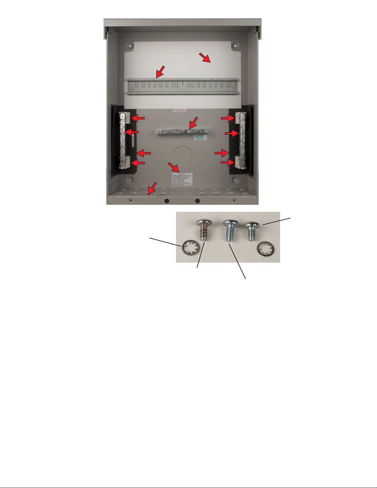
manuals.online logo
Brands
  1. Home
  2. •
  3. Brands
  4. •
  5. MidNite Solar
  6. •
  7. Medical Equipment
  8. •
  9. MidNite Solar MNPV8 series Reference guide

MidNite Solar MNPV8 series Reference guide

Other manuals for MNPV8 series

1

Popular Medical Equipment manuals by other brands

Itamar Medical WatchPAT Operation manual

Itamar Medical

Itamar Medical WatchPAT Operation manual

PROTEOR 1P650 KNEE Assembling and adjustment instructions

PROTEOR

PROTEOR 1P650 KNEE Assembling and adjustment instructions

Liberate Medical VentFree user manual

Liberate Medical

Liberate Medical VentFree user manual

Dicarre DA20 user guide

Dicarre

Dicarre DA20 user guide

Stryker Medical M Series Operation manual

Stryker Medical

Stryker Medical M Series Operation manual

Invacare ScanBed 750 user manual

Invacare

Invacare ScanBed 750 user manual

Getinge Arjohuntleigh Nimbus 3 Professional Instructions for use

Getinge

Getinge Arjohuntleigh Nimbus 3 Professional Instructions for use

Mettler Electronics Sonicator 730 Maintenance manual

Mettler Electronics

Mettler Electronics Sonicator 730 Maintenance manual

Pressalit Care R1100 Mounting instruction

Pressalit Care

Pressalit Care R1100 Mounting instruction

Denas MS DENAS-T operating manual

Denas MS

Denas MS DENAS-T operating manual

bort medical ActiveColor quick guide

bort medical

bort medical ActiveColor quick guide

AccuVein AV400 user manual

AccuVein

AccuVein AV400 user manual

agiliti NP Trio user manual

agiliti

agiliti NP Trio user manual

Rocket Medical Rocket Digital Oocyte Aspiration Pump Service manual

Rocket Medical

Rocket Medical Rocket Digital Oocyte Aspiration Pump Service manual

Monteris Medical Neuroblate Instructions for use

Monteris Medical

Monteris Medical Neuroblate Instructions for use

Otto Block 8E33 7 manual

Otto Block

Otto Block 8E33 7 manual

ADVANCED HOME CARE Helios Guide

ADVANCED HOME CARE

ADVANCED HOME CARE Helios Guide

NeuLog NUL-208 Guide

NeuLog

NeuLog NUL-208 Guide

manuals.online logo
manuals.online logoBrands
  • About & Mission
  • Contact us
  • Privacy Policy
  • Terms and Conditions

Copyright 2025 Manuals.Online. All Rights Reserved.

2
1
6
7
8
3
4
55
4
4
4
3
Rivet dinrail to
chassis
Step 1.
Punch out the plugs on the bottom
of the chassis #3-163-2.
Step 2.
Rivet the dinrail #3-165-1 to the
chassis.
Step 3.
Place the black insulator paper
#5-022-1 on both sides of the
chassis.
Step 4.
Screw down the white plastic
busbar insulators #5-015-2 with
#6-036-1 screws. Aluminum chas-
sis strips easily. Don’t over
tighten.
Step 5.
Attach busbars #9-037-1 to the
white busbar insulators.
Step 6.
Screw down the center busbar
#9-037-1 with #6-037-1 screws and
#6-017-1 lock washers. These
screws need to be torgued.
Step 7.
Lay down the white insulator paper
#5-036-1 or #5-036-2 around the
dinrail.
Step 8.
Apply all inside labels #10-008-1
(See page 2).
MNPV8 Procedure
May 30, 2011
Lock washer
#10 internal tooth
#6-017-1
Lock washer
#10 internal tooth
#6-017-1
Pan head screw 10 x 3/8
#6-007-1 Pan head screw
10-32 x 3/8
#6-036-1
Pan head screw
10-32 x 5/16
#6-037-1
Step 9.
Screw on the terminal blocks
#9-075-1 on each busbar #3-
174-1 using #6-059-1 screws and
#6-017-1 lock washers.
Step 10.
Attach labels on busbars off of
the #10-008-1 label sheet
9
10
10
9
Labels #10-008-1
Step 11.
Attach fuse holders (MNTS) with
15 amp fuses to dinrail.
Step 12.
Screw down busbars to fuse
holder. These need to be torgued
to 20 in lbs.
11
11
12
12
Step 13.
Attach clips to 10 gauge stranded
wire. White wire clips can be
found in clip bag #9-250-1. Red
wire clips can be found in #9-
249-1
Wiresizes are:
White
4 ea @ 4 ½”
2 ea @ 7”
2 ea @ 6”
Red:
8 ea @ 9”
13
13
Step 14.
Slide white wires and clips
through the bottom punch holes.
Slide the retaining nut onto the
wire and tighten the clip down to
the chassis.
Step 15.
Do the same thing for the red
wires.
Step 16.
Slide the ends of the white wires
into the busbars first and then the
red wires into the fuse holders
and tighten down the retaining
screws. All retaining screws in
both the busbar and fuse holders
need to be torgued to 20 in. lbs.
These retaining srews need to be
retorgued again in one hour.
14
14
14
14
15
15
15
15
16
16
Tighten down
the retaining nut.
17
17
Step 17.
Break out the blanks of the fuse
holder covers #5-033-1 leaving
the right one in place on the right
cover and the left blank in place
on the left cover. You will have to
take a utility knife and trim the
artifacts left the inside edges.
Step 18.
Snap in the fuse holder covers
into the deadfront making certain
to have the left one on the left
side and the right on the right.
There are pegs on the back of
each corner of the fuse holder
cover that have to go into four
holes on the deadfront. These
pegs are fragile and break off
easily.
Step 19.
Attach the deadfront #5-032-1,
placing the bottom end tabs into
holes in the chassis and snap-
ping in the top.
Step 20.
Make sure that the cover removal
note is placed where it can be
screwed down in between the
cover and the chassis.
19
19
20
20
Step 21.
Attach the label to the inside of
the cover #3-164-1 with the cover
facing upside down and the label
right side up. Attach the side
label.
The side label needs to have the
model number checked, in this
case, the MNPV12 chassis is
being used, the actual model of
the unit is an MNPV8 using MC4
type clips. Also select which
quarter of the year, in this case,
the second quarter (Q2) and the
last two digits of the year the unit
was assembled, (11).
21
21
21
21
Step 22.
Attach the cover to the chassis.
Step 23.
Screw down the cover using two
#6-007-1 screws and two #6-
017-1 lock washers. Make sure
the cover removal note is
screwed down with one of the
screws.
Step 24.
Attach a MidNite Solar badge
#5-029-1 to the lower right of the
cover.
22
22
24
24
23
23
23
23